During one-piece fitting crimping, the dies contact the ferrule, move it inward, compress the hose cover and reinforcement, deform the inner tube around the stem profile, and then release the assembly into a final relaxed geometry. The process is a controlled sequence of metal and elastomer deformation, not merely a machine producing one outside diameter. Some changes are elastic and partly recover after unloading; others remain as the assembled shape. Understanding these stages helps inspectors connect external measurements with internal evidence without assuming that diameter alone proves compatibility. Machine operation, die selection, insertion, and acceptance must always follow the approved equipment and hose-and-fitting data.
The Crimp Cycle Is a Five-Stage Material Sequence
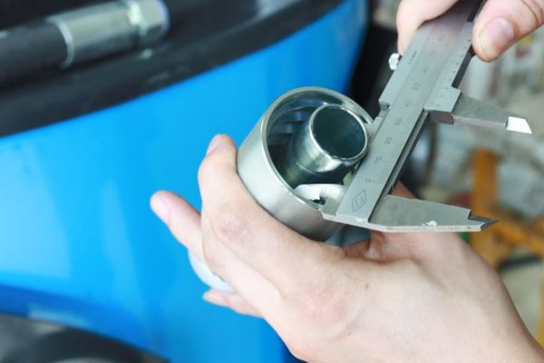
The clearest way to understand the joint is to freeze the cycle at five moments: initial contact, cover compression, reinforcement compaction, validated closure, and die release. Each moment changes a different part of the cross-section while the assembly remains one coupled system.
| Crimp stage | Dominant material response | What changes internally |
| Initial die contact | Ferrule begins elastic and plastic movement | Clearance closes and the sleeve starts approaching the hose cover |
| Cover compression | Elastomer is displaced and compacted | Cover thickness and local contact change beneath the ferrule |
| Reinforcement compaction | Structural layers move toward the supported stem | Radial restraint and load-transfer relationships develop |
| Validated closed condition | Metal and hose layers reach the specified loaded geometry | Tube conforms to the stem while the complete stack is constrained |
| Die release | Elastic recovery occurs in metal and elastomer | Final diameter, roundness, and residual contact settle after unloading |
Read the table as a sequence
These labels describe physical mechanisms, not operating instructions. The actual machine setting, die closure, crimp location, and final limits are specific to the exact hose, fitting, ferrule, equipment, and current specification.
Before the cycle begins, the hose must already be prepared and inserted correctly. Crimping cannot correct an incorrect hose series, wrong fitting, damaged tube, poor cut, incomplete insertion, or incompatible ferrule. It only deforms the assembly presented to the dies.
Stage 1: Die Contact Starts Ferrule Movement
The first stage begins when die segments touch the ferrule and establish contact around its circumference. At this moment, most internal hose layers have not yet reached their final compressed state, but alignment and contact geometry begin controlling everything that follows.
The dies apply load to the outside of the metal sleeve. Depending on the approved tooling geometry, contact may develop over defined axial and circumferential areas rather than as an ideal uniform pressure everywhere at once. The ferrule initially responds elastically, then begins permanent deformation as closure continues.
Initial contact and alignment
Small initial clearances between ferrule and hose cover reduce. If the assembly is off-center, positioned in the wrong axial location, or paired with incorrect tooling, die contact can become uneven. The operator should not compensate by forcing or improvising; the process must be stopped and identity, alignment, and approved setup verified.
Inside the hose, the stem provides an internal boundary, but the cover and reinforcement have not yet transmitted the full intended load toward it. The cross-section at this stage resembles nested layers beginning to lose clearance rather than a finished mechanical lock.
Stage 2: Cover Compression Moves Load Inward
As the ferrule continues inward, it compresses the hose material directly beneath it. In a no-skive design this includes the cover; in an approved skive design the material arrangement differs, so the correct preparation method is essential.
The cover is an elastomeric layer, not an incompressible spacer with nowhere to move. It changes thickness, shifts locally along available paths, and transfers load toward the reinforcement. Its surface may conform to ferrule features, while its internal boundary presses more firmly against the structural layer below.
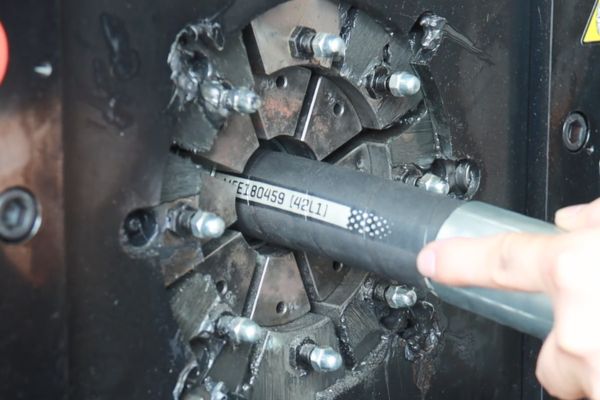
Cover displacement under constraint
This movement is constrained longitudinally by uncrimped hose at one side and fitting geometry at the other. Near ferrule edges, the transition from compressed to free hose can create a different strain pattern than the center of the crimp zone. That is one reason ferrule position and effective crimp length matter alongside final diameter.
Cover behavior cannot be judged by a generic expectation. Compounds, thicknesses, reinforcement relationships, and preparation requirements vary by hose series. Excessive damage, folding, or displacement seen in a section may guide investigation, but the approved design and validation evidence establish acceptance.
Stage 3: Reinforcement Compacts Toward the Stem
With further closure, radial load reaches the hose reinforcement and changes how its elements sit relative to one another and to the inner tube. The reinforcement is central to the hose’s structural role, so its controlled compaction is more significant than a cosmetic imprint.
Wire braid can change crossing geometry and local spacing as the circumference decreases. Spiral reinforcement responds according to its layered construction, while textile or thermoplastic systems follow different material paths. It is unsafe to assume that every hose should display the same wire movement or that visible wire imprinting must always appear.
Reinforcement response is construction-specific
As reinforcement compacts, it helps couple axial hose load into the crimped region. The ferrule restrains it from the outside, and the stem supports the tube from the inside. This produces the developing load-transfer zone in which hose and fitting begin acting as a mechanically joined assembly.
Uncontrolled over-compression, incorrect hose construction, wrong ferrule, or unsuitable stem geometry can disturb reinforcement instead of compacting it as intended. A final outside diameter alone cannot show broken, displaced, buckled, or otherwise damaged reinforcement hidden beneath the sleeve.
Stage 4: The Inner Tube Conforms Around the Stem
As the loaded cross-section approaches its validated closed condition, the inner tube is pressed against the hose-side stem geometry. Elastomer moves around serrations, grooves, or other controlled features, producing local conformance that contributes to mechanical grip.
The stem, tube, reinforcement, cover, and ferrule now form a compressed stack. Radial compression helps maintain interface contact, while stem features provide surfaces that react against relative axial movement. Retention results from this complete arrangement; it is not created by serrations alone or by one diameter reading.
Tube conformance and mechanical interlock
Tube deformation must preserve its containment function. A suitable profile allows controlled conformance without relying on cutting or uncontrolled thinning. Sharp damage, folds, severe displacement, or separation may be evidence of an incompatible combination or process problem, but section preparation can also create artifacts and must be documented.
Reaching the validated closed condition means following approved machine, die, positioning, and crimp data for the exact combination. It does not mean closing until the outside “looks tight.” No universal diameter, die size, or closure can be transferred safely between unrelated assemblies.
Stage 5: Loaded Geometry Reaches Its Defined Condition
Near the end of die closure, ferrule metal has undergone substantial permanent deformation while retaining an elastic component under load. Hose elastomers and reinforcement are also constrained in a state that is not identical to their later relaxed geometry.
At this loaded moment, die geometry and contact control the ferrule exterior. The machine display may describe a setting or tool position rather than the actual diameter at every point. Die size, machine target, under-load diameter, and final measured diameter are related but distinct data types.
Loaded state is not the inspection state
Internally, material displacement has largely reached the state intended by the approved process. The hose layers are compacted around the stem, and the effective ferrule region overlaps the intended engagement zone. Local pressure distribution can still vary along the crimp because of transitions, wall profiles, and different material responses.
Holding a defined machine condition does not let an inspector see internal integrity. The process record establishes that the specified cycle was commanded; it must be combined with machine calibration, correct tooling, part identity, positioning, measurement, and any required qualification evidence.
Die Release Produces Recovery and Final Geometry
When the dies open, applied load falls and both metal and elastomer recover to some degree. The ferrule keeps its permanent crimped shape, but its elastic portion relaxes. Hose layers also rebound within the constraint of the finished joint.
This recovery is commonly called springback when discussing the ferrule, though the final state reflects the whole assembly. The final crimp diameter measured after release may differ from the diameter under die load. Roundness can also settle as individual die-contact effects and material recovery become visible.
Elastic recovery and permanent set
Elastic recovery should be distinguished from permanent deformation. If everything returned to its starting geometry, no crimp would remain; if nothing recovered, loaded and unloaded dimensions would be identical. In reality, the finished assembly contains a permanent change plus residual elastic interactions among the ferrule, hose layers, and stem.
Measurement timing, location, orientation, part temperature, instrument condition, and calibration can influence the recorded result. An unexpected value should not automatically be blamed on springback, and operators must never compensate by manually over-crimping outside approved data.
Conclusion
Crimping a one-piece fitting is a staged conversion of separate metal and hose components into a coupled joint. Die contact moves the ferrule, cover compression carries load inward, reinforcement compacts, the tube conforms around the stem, and the loaded structure then relaxes into its final measured geometry. Elastic recovery explains why the under-load condition and final diameter differ, while permanent deformation preserves the joint. External measurements confirm important process features but cannot reveal insertion, reinforcement, tube, or stem conditions by themselves. To evaluate what happens during one-piece fitting crimping, prepare exact component identities, approved machine and die data, insertion and positioning records, calibrated measurements, controlled sections where needed, and the applicable performance validation.
FAQ
Does the final outside diameter prove the inside is correct?
No, it confirms only a defined external measurement. Internal insertion, reinforcement, tube condition, stem engagement, and compatibility require additional controlled evidence.
Does rubber flow inside the assembly during crimping?
Yes, elastomer deforms and moves locally under constraint. The amount and pattern depend on hose construction, stem geometry, ferrule design, and the approved crimp condition.
Should reinforcement always leave visible marks on the inner tube?
No, a universal imprint requirement would be unsafe. Reinforcement constructions and validated hose designs differ, and section preparation can change what is visible.
Why does the diameter change after the dies release?
The ferrule and hose layers recover elastically after unloading while retaining permanent deformation. The final relaxed geometry is therefore not identical to the loaded die-closed state.
Can a cross-section approve a crimped assembly by itself?
No, a section is local, destructive geometric evidence. It must be interpreted with drawings, process records, measurement data, preparation controls, and required performance validation.