One-piece fitting stem serrations create controlled surface geometry that the hose inner tube deforms around during crimping. This conformance contributes to mechanical interlock and resistance to axial movement, but the teeth do not retain the hose by themselves. Their profile must work with the inner tube, reinforcement, ferrule, insertion position, and approved compression of a specific assembly. Describing serrations simply as barbs hides the roles of tooth pitch, height, flank, crest, root, and location.
Serrations Convert Compression Into Controlled Grip
Serrations give the hose-side stem a repeating profile rather than a uniform cylinder. When the ferrule moves inward during an approved crimp, the hose structure is pressed toward that profile, and the inner tube changes shape around its crests, flanks, and roots.
The simplest visual is a row of shallow hills and valleys along the stem. Before crimping, the tube passes over those hills during insertion. During crimping, radial compression reduces the space available to the hose layers. Part of the elastomer moves locally into the valleys while other material remains supported over the crests. The resulting interface resists relative axial movement more effectively than uncontrolled contact on an arbitrary surface might.
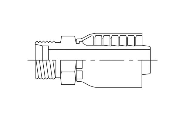
Controlled hose-side deformation
That description does not make serrations a universal sealing device or a stand-alone lock. Their contribution depends on whether the hose reached the correct insertion position, whether reinforcement is compressed as intended, and whether the ferrule maintains the designed radial condition. The complete load path still runs through the hose structure, compressed region, ferrule, and stem.
Anatomy of a Single Serration
One serration is defined by several connected features, and changing one feature changes how neighboring features behave. Engineers therefore review the full profile and its sequence rather than selecting a tooth by one impressive dimension.
Pitch, crest, and root
Pitch describes the spacing from one corresponding point on a tooth to the next. It controls how frequently the hose encounters changes in stem radius. A very close sequence creates many local transitions, while wider spacing gives the tube more distance to conform between features. Neither condition is inherently superior without the matching hose response.
The crest is the outermost part of the tooth, where initial local contact may be strongest. The root is the valley between teeth, where displaced elastomer may move during compression. Crest shape and root shape influence whether deformation is gradual or concentrated. Sharp corners can create localized stress, while an overly weak profile may not create the intended interlock.
Height and flanks
Tooth height is the radial difference between crest and root. It influences how far the tube must deform to follow the profile. The flanks connect those two levels and help determine how axial movement is resisted. Their direction, length, and edge form affect how load moves between hose material and metal.
| Serration feature | Mechanical role | Possible risk if poorly controlled |
| Pitch | Sets the frequency of tube displacement along the stem | Poor coordination can create uneven response or ineffective spacing |
| Height | Establishes the depth of local conformance | Excessive demand may damage the tube; insufficient engagement may reduce intended grip |
| Flank | Transfers part of the axial reaction across the interface | Abrupt geometry may concentrate stress or cut material |
| Crest | Creates a local contact high point | Sharp or inconsistent crests may score the tube |
| Root | Receives displaced material and joins adjacent flanks | Rough or abrupt roots may trap damage or disrupt conformance |
How the Inner Tube Responds During Crimping
The inner tube does not behave like a solid block being stamped into a mold. It is a compliant layer constrained by the stem on the inside and by reinforcement and ferrule compression on the outside, so its movement is local, three-dimensional, and influenced by the complete hose construction.
From insertion clearance to conformance
Before crimping, the stem must enter the hose by the approved preparation and insertion method. The tube stretches or slides over the stem profile while retaining enough integrity to perform its fluid-containment function. Forcing a mismatched stem into the hose can score, fold, or displace the tube before the ferrule ever reaches the dies.
As crimping proceeds, the cover and reinforcement compact and transmit radial load inward. The inner tube is pressed against tooth crests and moves toward adjacent roots. Some deformation is elastic and some may remain after unloading as part of the designed assembled geometry. The distribution is not expected to be identical at every point because the profile and surrounding hose layers vary along the axis.
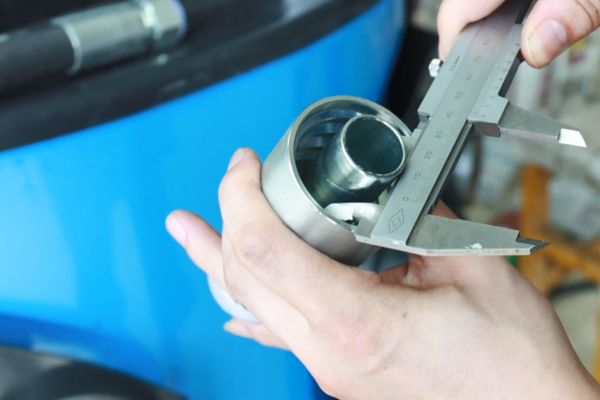
Rubber movement is not unlimited
The tube needs room and suitable material behavior to conform without being cut, excessively thinned, folded, or separated from reinforcement. A profile that demands too much local displacement can create a high-strain region. A profile that does not coordinate with the tube may also allow poor contact or an unintended load path.
This is why visible tooth marks after disassembly are ambiguous. They may show contact, but they do not prove that deformation stayed within acceptable limits or that the assembly delivered validated retention. Disassembly itself can drag material across the teeth and create additional marks.
Serrations Help Resist Axial Hose Movement
Axial retention develops when a pull on the hose is transferred through reinforcement and compressed hose structure into the fitting. Serration flanks contribute local reaction surfaces, while ferrule compression maintains contact and limits radial escape from the profile.
Think of the load moving through a sequence rather than stopping at one tooth. The hose reinforcement carries axial demand toward the end region. Compression couples the reinforcement, cover, and tube within the ferrule. The tube conforms around the stem profile, and the profile reacts against relative motion. Multiple features share the transfer according to their geometry and the local state of the hose.
A distributed load path
Not every serration necessarily carries equal load. Features near transitions, the insertion endpoint, or the edge of effective ferrule compression may see different conditions. Material tolerances and assembly variation also affect the distribution. Counting teeth cannot replace a review of effective engagement and complete assembly validation.
Friction also participates, but it should not be treated as a fixed property of the fitting. Surface condition, tube material, compression, contamination, and deformation all influence interface behavior. The engineering conclusion is therefore system-specific: serrations support retention as one element of a controlled crimped joint.
Aggressive Teeth Are Not Automatically Better
Deeper, sharper, or more numerous teeth can appear to promise stronger grip, yet greater geometric aggression also asks the inner tube to deform more severely. Useful design balances mechanical interlock with tube integrity, insertion behavior, and compatibility with the surrounding reinforcement and ferrule.
A sharp crest may produce strong local contact but can also score or cut the tube if the combination is unsuitable. A steep flank may react strongly against axial movement while concentrating strain near its edge. A deep root may accept more displaced material but could create severe local thinning or a geometry the tube cannot fill consistently. These are possible mechanisms, not automatic outcomes.
Balance interlock and tube integrity
The opposite assumption is equally unsafe. A smooth-looking or shallow profile is not necessarily ineffective. Some systems may use different stem textures, broader features, surface treatment, ferrule geometry, or hose behavior to achieve their approved performance. Visual aggression is not a rating.
Never grind, sharpen, deepen, or add serrations to an existing fitting. Such modifications change surface condition, dimensions, material integrity, and the validated load path. A modified fitting is no longer the defined component used in the approved hose-and-fitting system.
Serrated Grip Surfaces Differ From Flow and Sealing Surfaces
The stem’s hose-side serrations perform a different function from the internal bore and the connection-end sealing geometry. Confusing these surfaces can lead inspectors to accept damage in one area because it resembles intentional texture in another.
The internal flow passage should provide the geometry required by the fitting design without loose material, damaging burrs, or unintended restrictions. It is not made serrated to grip the hose. At the connection end, sealing may occur through a flare seat, O-ring, tapered thread, flat face, or another defined method. Those surfaces must be evaluated according to their own standards and cannot borrow acceptance logic from hose-side teeth.
Keep each surface tied to its function
On the hose side, the stem profile is located inside the inserted hose and is coordinated with ferrule compression. Even there, not every groove is necessarily a retention serration; some geometry may serve as a transition, identification feature, or manufacturing detail. Controlled drawings are needed to establish function.
Keeping functions separate helps diagnose leakage. A sound mechanical grip does not prove that the external connection seals, and a correct connection seal does not prove hose retention. The crimped joint and the port connection require independent verification.
Hose Construction Changes the Same Profile’s Behavior
The same one-piece fitting stem serrations can interact differently with hoses that share nominal size but use different tube compounds, reinforcement types, wall constructions, or dimensional ranges. Compatibility cannot be transferred by dash size alone.
Tube and reinforcement response
Inner-tube material affects insertion friction, elastic recovery, resistance to cutting, and how readily it conforms around a profile. Reinforcement construction influences how radial compression reaches the tube and how axial load arrives at the fitting end. A wire-braided structure, spiral-wire structure, textile reinforcement, or thermoplastic design should not be assumed to respond identically.
Cover thickness and construction also affect how the ferrule closes around the assembly. In skive and no-skive systems, the material present under the ferrule differs by approved design. Those differences change the path by which compression reaches reinforcement and tube.
Series identity matters
Hose manufacturer, hose series, construction, ID, fitting series, ferrule design, crimp equipment, die set, and current crimp specification must all be confirmed. A profile validated with one series is not automatically approved for another hose brand or construction, even if both are labeled with the same dash size.
When a hose change is proposed, treat it as a combination change. Review controlled compatibility data and the required validation plan rather than using visible serration marks or a successful insertion as proof.
Reading a Sectioned Crimp
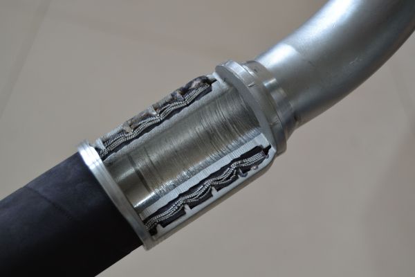
A sectioned assembly can show how local hose layers occupy the space between ferrule and stem. It is most useful when inspectors know what geometric questions they are asking and recognize artifacts introduced during sample preparation.
Inspect the insertion endpoint, stem-profile coverage, ferrule overlap, tube continuity, reinforcement position, and transitions at both ends of the crimped region. Look around more than one circumferential location when possible because a single cut may miss eccentricity or a localized condition. Record the section plane and preparation method.
Inspect geometry without overclaiming performance
The tube should be examined for conformance as well as possible cutting, folding, extreme thinning, or separation. Reinforcement should be reviewed for its intended position and for evidence that may indicate damage, without assuming that a particular wire imprint must always be visible. The ferrule and stem should also be checked for misalignment or unintended contact.
Section appearance cannot prove compatibility, pull-off resistance, impulse life, or pressure capability. Cutting and polishing can smear elastomer, move wires, and create apparent gaps. Use the section to compare actual geometry with controlled design intent, then combine it with part traceability, assembly records, measurements, and applicable validation results.
Conclusion
Stem serrations work by giving the inner tube a controlled profile to conform around while ferrule compression couples the hose structure to the fitting. Pitch, height, flanks, crests, and roots influence local material movement and axial load transfer, but none is a stand-alone measure of grip. Aggressive teeth can increase deformation demands and are not automatically safer; smooth-looking profiles may be valid within a different approved system. Keep hose-side grip features separate from flow and connection sealing surfaces, and expect hose construction to change the response. To evaluate one-piece fitting stem serrations, prepare the exact hose and fitting series, insertion and crimp records, controlled profile drawing, section-preparation details, and the applicable assembly validation evidence.
FAQ
Do deeper stem teeth always improve hose retention?
No, greater tooth depth does not automatically improve retention. It can increase local tube displacement and stress, so the full profile must be validated with the exact hose, ferrule, and crimp system.
Can a hydraulic hose fitting use a smooth stem?
Yes, some approved fitting systems may use smoother or differently textured hose-side geometry. Suitability depends on the complete validated design, not on whether the surface resembles conventional teeth.
Can the same serrated stem be used after changing hose brands?
Not without verified compatibility data. Different tube materials, reinforcement constructions, and dimensional ranges can respond differently even when the nominal hose size is the same.
Do visible tooth marks after disassembly prove a good crimp?
No, marks only show that contact or movement occurred. Disassembly may create additional scoring, and the marks cannot prove tube integrity, correct compression, or validated performance.
Can serrations alone prove hose-and-fitting compatibility?
No, serrations are only one component feature. Compatibility requires the exact hose, fitting, ferrule, insertion method, crimp equipment, and current approved crimp data.