One piece fitting concentricity matters because the connection, body, stem, and ferrule must follow a controlled common axis for predictable hose insertion and circumferential crimping. Each feature can have an acceptable local diameter while its center is offset from another feature. That relative eccentricity can create insertion resistance, uneven wall support, runout, or a finished assembly that does not follow its intended centerline. Concentricity is therefore an alignment question rather than a simple size check.
Map the Four Axes Before Measuring Alignment
The practical axis map starts at the connection end and follows the fitting through the body, hose-side stem, and ferrule. The question is not whether every axis is perfectly abstract; it is whether their relative alignment matches controlled design intent.
The connection axis is established by the functional thread, seat, flange, or port-engagement geometry appropriate to the fitting. The body axis follows the main fitting section or the defined drawing datum. The stem axis follows the hose-side support geometry, while the ferrule axis follows the sleeve bore or other defined cylindrical reference.
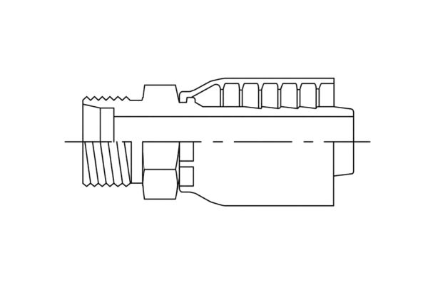
Connection, body, stem, and ferrule references
In a straight fitting, these axes may be intended to share a centerline. In an elbow, the connection and stem axes intentionally meet at an angle, but features belonging to each leg must still be aligned with their defined datums. Concentricity does not mean forcing every feature in an elbow onto one line.
A drawing or inspection plan should state which feature is the datum and which feature is being evaluated relative to it. Without that relationship, a reported “off-center ferrule” is only an observation and not a complete dimensional result.
The axis map should also identify the axial span over which each feature is evaluated. A short cylindrical land and a long stem can react differently to the same local measurement error, and a transition should not be used as though it were a stable datum surface. Stating feature length and measurement plane helps reviewers reproduce the setup and decide whether the observed offset can affect hose engagement or connection alignment.
Correct OD Does Not Prove a Common Center
Diameter tells the distance across a feature; it does not tell where that feature is located relative to another axis. A circular stem and circular ferrule can both meet their local size requirements while their centers are offset.
Imagine two rings of correct diameter drawn on transparent sheets. Sliding one ring sideways does not change either diameter, but their centers no longer coincide. In a fitting, that offset changes clearance on opposite sides of the stem and ferrule. One side becomes tighter while the other becomes more open.
Size and location require separate evidence
Wall-thickness readings can expose some eccentric relationships when inside and outside features are involved, but one reading is insufficient. Measurements at several circumferential positions and a defined axial location may be needed. The suitable instrument depends on feature access, required uncertainty, production volume, and the controlled inspection plan.
Do not convert this concept into a universal tolerance. Acceptance values must come from the part drawing, specification, or responsible engineering authority for the exact fitting series.
Pre-Crimp Effects on Hose Insertion
Eccentric stem and ferrule geometry can make insertion feel uneven before the assembly reaches the crimp machine. That resistance should trigger verification, not additional force.
Unequal entry clearance
If the ferrule bore is offset relative to the stem, the annular space available for the hose wall can be smaller on one side. The hose may rub or pinch locally while the opposite side has more clearance. A stem with runout can also sweep toward the ferrule as the part rotates, creating a changing tight point.
Insertion resistance is not proof of concentricity failure. Wrong hose ID, incompatible hose construction, damaged or burred parts, incorrect preparation, tube folding, contamination, or hose ovality can produce similar symptoms. Inspectors should confirm component identity and condition before assigning a geometric cause.
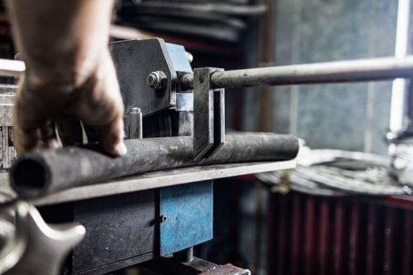
Forcing hides the evidence
Forcing the hose can score the inner tube, displace the cover, bend a marginal stem, or push material into an unintended position. It also destroys useful information about where resistance began. Stop, isolate the parts, and document insertion depth and orientation.
Compare the fitting without hose, then rotate or inspect it against defined datums. If resistance repeats at the same fitting orientation across suitable samples, alignment becomes a stronger hypothesis. If it follows the hose orientation, hose memory or ovality may be more likely.
Off-Center Geometry Changes Radial Compression
During crimping, the ferrule moves inward around the hose while the stem supports the inside. Relative axis offset creates unequal starting space and can change how the hose layers are compacted around the circumference.
Tight side and open side
On the side where ferrule and stem are closer, the hose wall may encounter constraint earlier. The opposite side may have more space and follow a different deformation path. The dies can still produce a plausible outside diameter while internal compression and material movement are asymmetric.
Reinforcement, tube, and cover respond according to their construction, so the effect cannot be predicted from offset alone. A small apparent eccentricity may be within the controlled design, while a larger or differently located offset may be unacceptable. Only specified geometry and validation can set that boundary.
Circumferential evidence
Measure final ferrule geometry at defined orientations and axial locations where the procedure requires it. Roundness, wall relationships, die marks, and component axis evidence can indicate whether compression was uniform enough to investigate further.
A section through one plane may show the tight and open sides, but it may also miss the maximum offset. Orthogonal sections or nondestructive dimensional methods can be considered under a qualified inspection plan. Section preparation can move elastomer or release residual stress, so geometry should be documented before cutting when possible.
Post-Crimp Symptoms Need Careful Interpretation
Misalignment may appear after crimping as visible ferrule offset, stem runout, uneven die-mark depth, asymmetric transitions, or an assembly end that seems to lean. None of these observations proves a single root cause.
| Observation | Possible alignment issue | Next measurement |
| Ferrule appears off-center around the stem | Ferrule-axis offset, sleeve deformation, or viewing/parallax effect | Ferrule bore or OD axis relative to a defined stem datum |
| Hose insertion was tight at one orientation | Reduced annular clearance from eccentricity or a bent stem | Clearance or runout map before crimping and hose condition check |
| Final crimp is less round in one plane | Uneven support, tooling condition, or starting eccentricity | Diameters at defined orientations, die inspection, and starting-part geometry |
| Fitting end seems angled from the hose | Stem/body misalignment, hose memory, routing force, or cut-end issue | Part runout without hose and relaxed hose centerline observation |
| Die marks differ around the sleeve | Tooling contact variation, setup, or eccentric component stack | Die condition, machine centering, and ferrule geometry |
Symptoms point to several possible causes
Apparent hose curvature deserves separate review. Hose stored in a coil can retain memory and curve even when the fitting is aligned. Routing forces or an angled cut can also affect appearance. Let the unpressurized assembly relax safely and compare the fitting axis with controlled references rather than using the hose centerline alone.
Concentricity, Straightness, and Runout Are Different
These terms are related in shop conversation but answer different questions. Keeping them separate prevents an indicator reading from being labeled as a complete concentricity result.
Concentricity or coaxiality concerns the relationship between axes or centers of features. Straightness concerns whether a line element or axis departs from straight form. Runout is the variation observed when a feature rotates relative to a datum axis, combining effects from size, form, centering, and orientation.
Report the characteristic actually measured
A bent stem can create runout because its axis is not straight. A perfectly straight stem can also show runout if it is mounted off-center relative to the rotation datum. A ferrule may appear eccentric without the stem being bent. The inspection result should therefore state the datum, feature, method, and measured characteristic.
This article uses practical language rather than prescribing a GD&T method. The controlled drawing and inspection authority should determine whether runout, coaxiality, wall-thickness variation, or another characteristic best verifies the functional alignment requirement.
Choose Evidence That Matches the Alignment Question
No single instrument is universally correct for one-piece fitting alignment. The method must resolve the relevant axes with suitable uncertainty and without using a poor surface as the datum.
A rotational indicator setup may help evaluate runout when the fitting can be referenced repeatably. Optical or coordinate methods may help locate axes of accessible features. Bore and wall measurements can reveal eccentric relationships, while functional gauges may screen insertion or assembly conditions without fully quantifying axis offset.
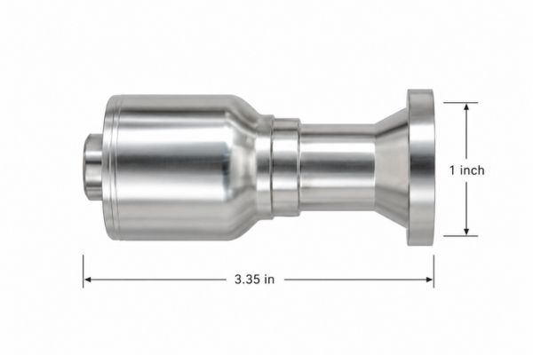
Match the method to the axis question
Fixture quality matters. Clamping on a rough, tapered, or deformed surface can create apparent runout. Excessive clamping force can distort a thin ferrule. Dirt, burrs, plating buildup, and thread seating variation can also move the part relative to the datum.
Record instrument, fixture, datum simulation, axial location, rotation method, temperature where relevant, and uncertainty. A result without those details is hard to compare across shifts or suppliers. Do not infer thread accuracy or sealing-face flatness from an axis result; those are separate functional checks.
Isolate the Defect From Part to Hose Assembly
Troubleshooting should progress from individual components to the assembled hose so each stage either preserves or changes the observed alignment. This prevents the crimp operation from receiving blame for a pre-existing bent or eccentric part.
First inspect and identify the unassembled fitting. Evaluate connection, body, stem, and ferrule axes using controlled datums. Check for burrs, damage, incorrect retention of the ferrule, and bent geometry. Compare traceable samples without selecting only the best-looking piece.
Preserve evidence through each assembly stage
Next document hose identity, cut condition, preparation, ovality or memory observations, and insertion behavior. Do not force difficult insertion. Verify approved compatibility and insertion instructions. Then review machine centering, die identity and condition, axial position, and crimp records.
After crimping, measure final diameter and roundness at defined locations, inspect runout and visible alignment, and use controlled section evidence only if needed. Compare the finished result with pre-crimp measurements. If the axis error first appears after crimping, investigate tooling, positioning, internal support, and component interaction; if it existed before, contain the relevant parts and trace the source.
A section that appears symmetric is still only one destructively prepared plane. Use it to test a defined hypothesis, then compare it with the part measurements and process history. Visual symmetry alone cannot establish hose compatibility, retention, pressure capability, or acceptable alignment around the complete circumference.
Conclusion
Concentricity is the relative alignment of functional axes, not proof that each local diameter is correct. Connection, body, stem, and ferrule geometry must be mapped to controlled datums, with intentional elbow angles kept separate from unwanted offset. Eccentricity can reduce insertion clearance on one side and change circumferential compression during crimping, yet hose memory, tooling, and preparation can create similar symptoms. Distinguish axis relationships from straightness and runout, and choose inspection evidence that answers the specific question. For a one-piece fitting concentricity review, prepare part drawings, datum definitions, pre-crimp geometry, hose and insertion records, machine and die information, final roundness measurements, and traceable section evidence where required.
FAQ
Is runout the same as fitting concentricity?
No, runout is observed variation during rotation and can combine centering, form, and orientation effects. Concentricity concerns the relationship between feature axes or centers.
Does an off-center-looking ferrule prove a defect?
No, viewing angle, sleeve profile, or hose position can affect appearance. Measure the ferrule relative to a defined stem or body datum before deciding.
Should a hose be forced onto a fitting if insertion is tight?
No, forcing can damage the tube or hide evidence. Stop and verify hose identity, fitting series, preparation, component condition, and alignment.
Does stem runout always mean the stem is bent?
No, an off-center straight stem or poor fixture datum can also create runout. Separate straightness, centering, fixture, and rotation effects.
What should post-crimp alignment inspection include?
Include defined final diameters, roundness, axis or runout evidence, die and machine condition, visible transitions, and comparison with pre-crimp component geometry.