One-piece fitting transition geometry affects strength by changing how load flows between the connection, body, neck, elbow, and hose-side stem. Abrupt changes in section can concentrate local stress even when every area looks thick and robust. Smoother transitions may distribute load more gradually, but appearance alone cannot prove pressure or fatigue performance. Material condition, wall geometry, surface features, manufacturing quality, assembly loading, and validated test data still control the decision.
Follow the Load Path Through the Fitting Body
A fitting carries load through connected sections rather than through isolated dimensions. Pressure, hose reaction, installation forces, vibration, and external bending enter at different locations and must pass through the body to reach the connection or hose assembly.
Begin at the port or mating connection. Pressure creates loads on internal projected areas, while the connection reacts through threads, a flange, a nut-and-seat interface, or another defined geometry. Those forces enter the body and continue through hexes, necks, elbows, and the stem root. Hose weight, routing, and motion can send bending in the opposite direction from the stem toward the body.
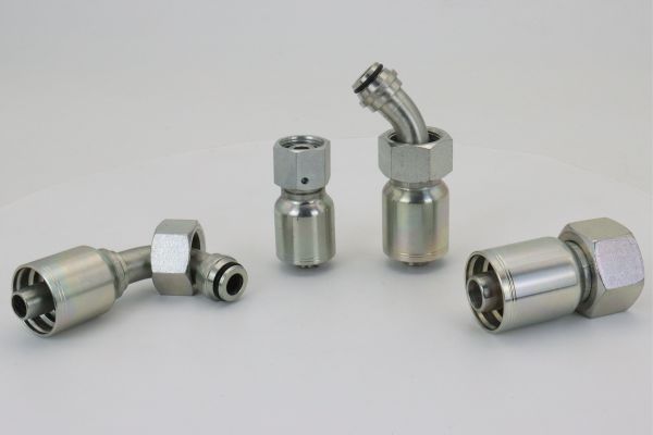
Map where forces enter and change direction
The path is not always centered. An elbow creates an offset between the hose centerline and connection, so pressure and hose reactions can generate bending as well as axial load. Installation misalignment can add side load that the nominal pressure calculation does not describe.
Mapping these directions on a drawing is more useful than identifying the thickest section. The review should ask where load enters, where it changes direction, which cross-sections carry it, and where stiffness changes abruptly.
Identify the Major Section Changes
The connection end, wrenching body, intermediate neck, elbow, stem root, and hose-side stem usually differ in outside form, bore, and wall distribution. Every change is a transition that can alter the local load path.
A hex body changes from flats and corners to a round neck. A drilled or formed passage may change direction inside an elbow. The outside may taper while the bore remains constant, or the bore may change while the outside looks smooth. At the hose side, the stem root joins a larger body before narrowing into the insertion profile.
Review internal and external sections together
External appearance can therefore hide an internal section change. A generous outside radius does not guarantee a smooth internal passage transition, and a constant outside diameter does not prove constant wall thickness. Drawing review should examine both surfaces and their relative centers.
Manufacturing allowances also matter. Machining undercuts, tool-clearance grooves, thread runouts, wrench flats, brazed or formed regions, and retained ferrule features can change the effective section. Their presence must be interpreted against controlled design intent rather than treated as cosmetic details.
Abrupt Changes Raise Local Stress Concentration
When load crosses a sudden change in stiffness or section, stress does not remain evenly distributed. It crowds near the discontinuity, creating a local peak above the nominal average for the larger section.
One useful analogy is traffic entering a narrow lane. The total flow continues, but vehicles crowd near the merge. In a fitting, force lines crowd around a sharp shoulder, small root, hole intersection, or sudden wall change. The analogy explains localization, not a formula or life prediction.
The severity depends on shape, load direction, material, surface condition, and neighboring geometry. A sharp shoulder under bending may be more critical than the same feature under a different load orientation. Internal pressure can interact with external bending and residual manufacturing stress.
Stress concentration identifies a zone deserving analysis; it does not guarantee a crack will begin there. Validated engineering calculations, material data, manufacturing control, and applicable testing are required for a safety-critical conclusion.
Sharp shoulders and smooth transitions compared
Smoother geometry can reduce how abruptly load changes direction, but a transition must fit the complete section and manufacturing process. Simply rounding the visible edge does not solve every internal or dimensional issue.
| Transition feature | Load effect | Drawing question |
| Sharp shoulder between large and small sections | Can concentrate load at a narrow root | What are the controlled root geometry and nearby wall thickness? |
| Gradual taper or fillet | Can spread the change over more distance | Does the inner passage support the same smooth load path? |
| Undercut or relief groove | May control clearance but reduce local section | Is its function defined, and how is its root controlled? |
| Bore intersection in an elbow | Changes internal wall distribution and load direction | What is the minimum controlled wall around the intersection? |
| Stem-root transition | Transfers hose-side bending and axial load into the body | How do outside profile, bore, and ferrule relationship align? |
A larger fillet radius often lowers geometric abruptness conceptually, but no universal radius can be prescribed. Space, wrench clearance, sealing geometry, bore location, machining access, and mating components may constrain the design.
Surface finish and tool path at the transition are part of the review. A smooth nominal radius with a deep machining mark can create a local initiation feature. Conversely, a visible tool pattern is not automatically unacceptable without drawing criteria and evidence of its depth and orientation.
Elbows Add Direction Change and Bending Effects
Elbow fittings deserve separate attention because the load path turns while the internal passage and external body redistribute wall material. The inside and outside of the bend do not experience identical geometry or loading.
Pressure-related forces act through the curved passage and connection offsets. Hose routing can add a moment at the stem, particularly when the hose is pulled away from its natural tangent, violates the specified bend radius, or is installed with twist. Equipment vibration and motion can repeat these loads.
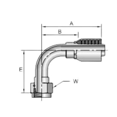
Curved passages and offset reactions
The elbow may transition from a connection body into a curved tube-like section and then into the stem root. Bore intersections, formed bends, machining blends, or locally thin walls can become review zones. The highest-risk area cannot be declared from appearance alone because construction methods differ.
Straight fittings are not automatically stronger, and elbows are not automatically weak. They carry different geometry and load paths. The responsible comparison uses controlled dimensions, exact materials, application loads, routing, manufacturing method, and validated pressure and fatigue evidence.
More Material Can Move Rather Than Remove the Weak Point
“Thicker everywhere” is not the same as better stress distribution. Adding material changes stiffness, and a stiffer region can move deformation and stress toward the next thinner or more abrupt transition.
If a neck is enlarged without blending its connection to the body, the new shoulder may become the dominant concentration. Thickening the outside while leaving a sharp internal bore intersection can preserve the hidden critical feature. Extra material can also reduce clearance, increase weight, or make adjacent sections less able to accommodate movement.
Trace the next stiffness change
The goal is continuity of the load path, not maximum mass. Engineers consider gradual section changes, aligned walls, suitable transitions, load direction, and manufacturability as a connected problem. Local reinforcement may be useful when designed and validated, but it is not a substitute for understanding where load goes next.
This myth correction matters in purchasing comparisons. A heavier fitting should not be called stronger from mass alone. Weight may reflect a different connection size, manufacturing method, or excess stock outside the functional load path.
Transition Zones Can Influence Fatigue Initiation
Repeated loading can make local stress concentration more important than a single static event. Pressure cycles, vibration, hose motion, equipment shock, and installation strain may repeatedly load the same transition.
Fatigue cracks can initiate from a surface or internal feature where cyclic stress, material condition, and local geometry combine unfavorably. Machining marks, scratches, corrosion pits, decarburization, laps, or other discontinuities may affect initiation depending on their location and orientation. None should be declared the cause without fracture evidence.
A high-risk zone is not a predicted failure location. Residual stress, surface treatment, material cleanliness, load spectrum, environment, and actual assembly routing all influence life. A fitting that passes one static pressure event has not thereby demonstrated fatigue performance for every application.
When a crack is investigated, preserve the fracture origin and compare it with the drawing transition, manufacturing records, material evidence, and loading history. Grinding or cleaning the suspected area can remove the very evidence needed to distinguish geometry from material or service damage.
Keep transition geometry separate from other functions
Body transitions should not be confused with connection sealing geometry or hose crimp dimensions. These functions interact in the complete fitting but require different acceptance evidence.
A flare seat, O-ring face, tapered thread, or flange surface must meet its defined sealing and connection requirements. Making a nearby body transition smoother does not correct a damaged seat or wrong thread. Likewise, changing ferrule compression cannot repair a weak body section and may create a new hose-end problem.
The stem and ferrule form the crimped hose joint, while the body transfers load toward the external connection. Their transition at the stem root deserves review, but hose compatibility still depends on the exact hose series, fitting series, ferrule, insertion, and current crimp data.
Keeping these checks separate produces traceable decisions. A part can pass transition-geometry inspection and fail sealing-face inspection, or pass connection checks while lacking approved hose compatibility. No single visual approval covers all functions.
Drawing Review for Geometry Continuity
Review the drawing as a load-path map from the connection to the stem. The purpose is to identify discontinuities, confirm controlled dimensions, and decide where analysis or validation evidence is needed.
Mark connection reaction surfaces, bore centerlines, hex-to-neck changes, elbow intersections, wall-thickness transitions, relief grooves, stem roots, and ferrule attachment features. Examine internal and external contours together. Record datums and drawing revision so different reviewers discuss the same geometry.
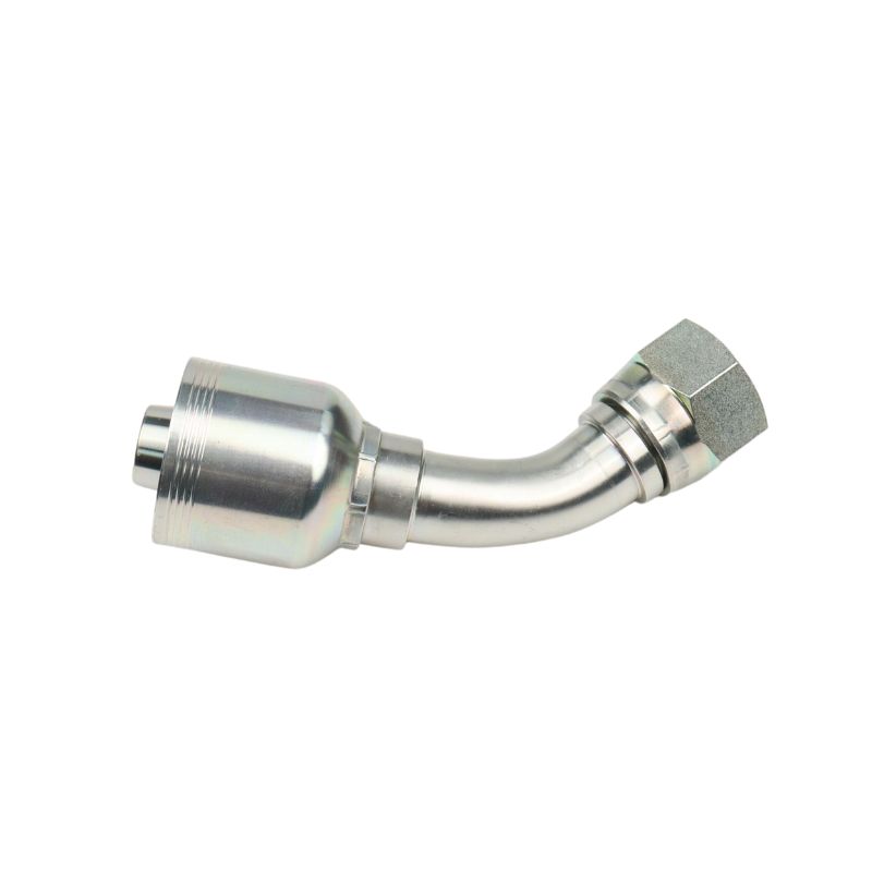
Ask continuity questions at every transition
Ask what load crosses each transition, whether the section changes abruptly, whether internal and external profiles remain aligned, and what manufacturing feature controls the root. Check material and process requirements, surface condition criteria, inspection method, and any applicable validation records.
For an application review, add hose routing, installation envelope, vibration, external loads, pressure cycles, fluid, temperature, and corrosion exposure. A visually smooth CAD model is only a geometric representation; it does not prove material properties, manufacturing conformity, residual stress, or validated strength.
Where revisions exist, compare the changed transition and every adjacent section so an improvement in one local view does not conceal a new discontinuity elsewhere.
Conclusion
Transition geometry matters because every force must pass through changes between the connection, body, neck, elbow, and stem. Sharp shoulders, bore intersections, reliefs, and wall changes can localize stress, while smoother continuity may distribute it more gradually. Adding material without tracing the next stiffness change can simply move the critical zone. Elbows add offset and bending, and repeated service loads can make local features relevant to fatigue initiation, but no visual feature guarantees a failure or a safe life. To review one-piece fitting transition geometry strength, prepare controlled internal and external drawings, exact material and manufacturing records, application load and routing information, surface evidence, engineering analysis, and applicable pressure and fatigue validation.
FAQ
Does a larger fillet radius always make a fitting stronger?
No, a smoother transition may reduce local concentration, but strength depends on the complete internal and external geometry, material, load, manufacturing condition, and validation.
Are elbow fittings weaker than straight fittings?
Not automatically. Elbows have a different load path and bending geometry, so compare exact designs and validated application evidence rather than the angle alone.
Does greater wall thickness guarantee higher strength?
No, added thickness can move stress to an adjacent transition or leave a hidden internal discontinuity. Load-path continuity matters more than mass alone.
Can machining marks cause fatigue cracks?
They can be possible initiation contributors when depth, orientation, location, and cyclic stress align unfavorably. Fracture and manufacturing evidence are needed to confirm causation.
Does a smooth CAD model prove fitting strength?
No, CAD appearance does not establish material condition, manufactured dimensions, surface integrity, residual stress, or pressure and fatigue performance. Use controlled engineering and validation evidence.