A threaded fitting can screw into a port and still be the wrong connection. Similar diameters, matching thread counts, or a few smooth turns do not prove compatibility—and they do not establish pressure-tight performance.
For hydraulic fittings, valve blocks, and equipment ports, thread quality affects assembly, serviceability, and sometimes the pressure seal itself. Reliable results require more than selecting a cutter with the correct angle. The thread standard, pitch, diameter, taper, effective length, and sealing arrangement must work together.
Identify the Complete Thread Before Machining
A request for a “half-inch pipe thread” leaves several important questions unanswered. Is the connection NPT, G, R, Rp, or Rc? Is it internal or external? Where does the seal form?
Pipe thread sizes are nominal designations. A nominal half-inch pipe thread does not have a measured outside diameter of half an inch.
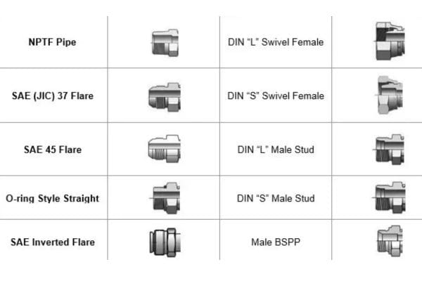
Before selecting tooling or approving a drawing, confirm:
- Thread standard and complete designation.
- Nominal size and pitch or threads per inch.
- Internal or external thread.
- Parallel or tapered geometry.
- Right-hand or left-hand direction.
- Required tolerance and effective thread length.
- Sealing arrangement and mating component.
- Inspection and acceptance requirements.
For hydraulic applications, also identify the operating fluid, pressure, and temperature. These conditions influence the complete connection specification, including materials and seals.
A complete thread designation prevents machining errors; a complete interface specification prevents connection errors.
Understand the Four Main Thread Families
| Thread family | Included angle | Geometry | Pitch designation | Sealing consideration |
| Metric M | 60° | Parallel | Pitch in millimeters | A separate feature generally provides pressure sealing |
| UNC/UNF | 60° | Parallel | Threads per inch | A separate feature generally provides pressure sealing |
| BSP | 55° | Parallel or tapered | Threads per inch for the designated size | Depends on whether the connection uses G, R, Rp, or Rc |
| NPT | 60° | Tapered, 1:16 on diameter | Threads per inch | Pressure-tight assembly normally requires suitable thread sealant |
A shared thread angle does not establish interchangeability. Metric and UN threads may differ in pitch, diameter, and tolerances despite both using a 60° profile.
Likewise, NPT and tapered BSP threads share a nominal taper but have different thread forms and size relationships. They should not be substituted for one another.
BSP Designations Need Particular Attention
BSP terminology is frequently simplified too far:
- G: Parallel pipe threads associated with connections that seal through another feature, such as a gasket, O-ring, or mating seat.
- R: Tapered external pipe threads.
- Rp: Parallel internal pipe threads in the pressure-tight thread-joint system.
- Rc: Tapered internal pipe threads in that system.
Rp is parallel, not tapered. It should not automatically be treated as equivalent to G.
BSW is a Whitworth fastening thread series, not another name for BSPP.
When Is CNC Thread Milling the Right Choice?
Thread milling generates a thread through coordinated cutter rotation and machine movement. It offers useful control over cutting engagement and finished size.
It can be attractive for larger threads, expensive workpieces, and applications where controlled size adjustment is valuable. Depending on the cutter design, one tool may also cover several thread diameters.
However, cnc thread milling is not automatically better than tapping. Suitable taps can produce accurate threads, including tapered pipe threads, and may offer shorter cycle times in appropriate applications.
Compare the following before choosing a process:
- Thread diameter, depth, and production quantity.
- Workpiece material and hardness.
- Machine interpolation capability.
- Tool access, overhang, and setup rigidity.
- Required accuracy and surface condition.
- Tooling cost and cycle time.
Thread mills can still chip or break. Their advantages depend on correct tooling, programming, and operating conditions—not immunity to failure.
Control the Pre-Hole Without Confusing It with Pitch Diameter
For conventional internal thread milling, the prepared hole strongly influences the minor diameter, retained thread crest, and material removed by the cutter.
It does not independently determine the finished thread fit.
The cutter profile and programmed path influence the generated thread geometry and pitch diameter. Tool deflection, runout, and wear can also affect the result.
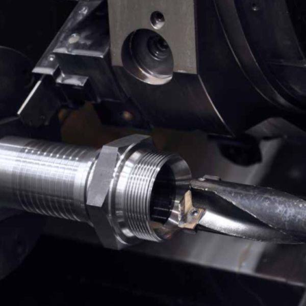
If a thread is tight, enlarging the pre-hole is not a universal correction. First determine whether the problem concerns pitch diameter, minor diameter, taper, burrs, or another feature.
The hole preparation method should meet the drawing requirements. Drilling may be sufficient in some applications; boring, reaming, or milling may be appropriate when tighter dimensional or geometric control is needed.
The measurement matters more than the unit marked on the drill. A metric-sized tool can prepare an inch-thread hole if the resulting diameter meets the specified requirements.
Can an NPT Pre-Hole Be Tapered?
Yes. Both cylindrical and tapered hole preparation can be used, depending on the thread mill and process.
A tapered pre-hole can distribute cutting engagement more evenly along the thread length. A cylindrical pre-hole may also be appropriate with suitable tooling and machining strategy.
The correct choice follows the cutter’s application requirements and the finished thread specification. Neither approach should be declared universally mandatory.
Match the Cutter to More Than the Thread Angle
A 55° cutter should not be substituted for a 60° cutter. However, matching the angle alone is still insufficient.
Check the cutter’s:
- Supported thread standard and pitch range.
- Internal or external application.
- Full-profile or partial-profile geometry.
- Crest and root capabilities.
- Cutting diameter and usable reach.
- Suitability for the workpiece material.
A full-profile cutter may generate features that a partial-profile cutter leaves dependent on previous machining. That distinction affects hole preparation and finished geometry.
Some tools can produce several sizes; others have narrower applications. Tool sharing should follow the stated application range rather than visual similarity.
For deep threads, check both cutting reach and shank clearance. Excessive overhang reduces rigidity and can produce taper, chatter, or inconsistent size even when the programmed dimensions are correct.
Convert Inch Pitch Accurately
UNC, UNF, and common pipe threads use threads per inch, abbreviated TPI.
The conversion is:
Pitch in millimeters = 25.4 ÷ TPI
For example, 14 TPI corresponds to approximately 1.814285714 mm.
An inch thread can be programmed in metric units. The requirement is sufficient numerical precision and consistent units throughout the program. Rounding 14 TPI to 1.8 mm introduces an unnecessary pitch error.
Also distinguish pitch from lead. For a single-start thread, they are equal. For a multi-start thread:
Lead = pitch × number of starts
The programmed axial movement per revolution must match the required lead.
Avoid copying a generic “thread depth” coefficient into a program without checking its definition. Basic triangle height, radial thread depth, and diameter differences are distinct dimensions.
Program Taper and Compensation Carefully
The 1:16 taper used by NPT and tapered BSP threads describes diameter change relative to axial length.
Over an axial distance of 16 units:
- Diameter changes by 1 unit.
- Radius changes by 0.5 unit.
Confusing diameter and radius produces the wrong taper.
A conventional internal tapered pipe thread is larger at the opening and smaller farther into the hole. Nevertheless, the actual toolpath must account for tool geometry, coordinate direction, and control capabilities.
Do not assume that every tapered thread mill uses an identical programming method.
Cutter compensation also requires context. “Increase compensation to loosen the thread” is not a safe universal instruction. The effect depends on internal versus external machining, compensation conventions, and how the toolpath was generated.
The reliable sequence is to machine a first article, inspect it, apply a small adjustment in the verified direction, and inspect again.
Set Cutting Passes and Entry Moves for the Application
Not every thread requires multiple radial passes. Some tools and conditions support a single cutting pass; others benefit from roughing and finishing passes.
Pass selection depends on thread depth, material, cutter diameter, overhang, and machine rigidity.
A fixed finishing allowance is equally unsuitable as a universal rule. Any stated allowance should identify whether it is radial or diametral and be appropriate for the tool and material.
Entry and exit instructions also need precision. Moving axially through the clear center of a prepared hole is different from plunging a cutting edge into solid material.
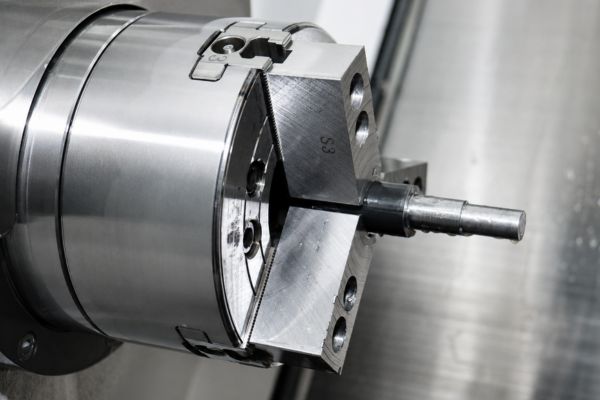
A suitable strategy should:
- Maintain clearance during positioning.
- Introduce cutting engagement smoothly.
- Provide room at the bottom of a blind hole.
- Prevent the cutter from dragging across the finished thread during withdrawal.
- Support chip evacuation.
When chatter appears, inspect workholding, overhang, runout, wear, and cutting engagement before automatically increasing speed or reducing feed.
For internal milling, also account for the difference between cutting-edge feed and tool-center feed. An incorrect feed interpretation can overload the cutter.
Inspect the Thread Before Approving Production
A mating fitting is useful for an assembly check, but it is not a replacement for specified inspection.
The inspection plan should address:
| Inspection item | What it helps verify |
| Drawing and thread designation | The correct standard and size were produced |
| Appropriate thread gauges | Compliance with specified functional limits |
| Tapered-thread gauge position | Conformance to the applicable gauging requirements |
| Minor diameter | Suitable internal thread geometry |
| Effective thread length | Adequate usable engagement |
| Visual surface inspection | Burrs, tearing, damage, or incomplete threads |
| Specified leak or pressure testing | Performance under the defined test conditions |
Parallel and tapered threads require different gauging approaches. Gauge selection and acceptance criteria should follow the applicable specification.
Dimensional inspection and sealing tests answer different questions. Passing one does not automatically establish the other.
Likewise, a low-pressure air check does not demonstrate suitability for every hydraulic operating condition. Test medium, pressure, duration, and acceptance limits must be defined.
Treat Sealing as Part of the Complete Connection
Ordinary NPT pressure-tight joints normally require an appropriate thread sealant. NPT should not be confused with NPTF dryseal geometry.
Choose sealing materials for compatibility with the fluid, temperature, and connection instructions. Avoid applying excess material that could enter the system.
For G-thread connections, identify the actual sealing feature. Correct threads cannot compensate for a damaged O-ring groove, unsuitable gasket, or mismatched seat.
When a connection leaks, check the thread identity and sealing arrangement before applying more tightening force. Overtightening can damage threads, distort sealing features, or crack components.
Pressure capability also belongs to the complete connection. A thread designation alone does not establish a safe working pressure.
Information to Include in a TOPA Inquiry
Clear specifications make hydraulic product discussions more efficient and reduce the risk of supplying a visually similar but unsuitable connection.
When contacting TOPA about hydraulic fittings, hoses, cylinders, or related components, include:
- A drawing or complete thread designation.
- Clear photographs of the thread and sealing face.
- Mating component details.
- Working pressure, temperature, and fluid.
- Material and surface treatment requirements.
- Quantity and required inspection documentation.
If the interface is unidentified, mark it as “to be confirmed” rather than assigning a thread type from appearance alone. Measured diameter and pitch can assist identification, but they should be considered alongside the sealing geometry and available documentation.
For TOPA customers, the most useful starting point is the complete connection requirement: what must fit, where it must seal, and how acceptance will be checked. Establishing those details early supports clearer quotations, more meaningful sample evaluation, and fewer avoidable problems during assembly.