An intentional edge is specified in the drawing; burrs on one-piece hydraulic fittings are unwanted protrusions of material left by machining or subsequent processing. Effective one-piece fitting burr inspection begins by locating the edge and identifying its function, not by calling every sharp-looking feature defective. A normal chamfer can guide assembly, while a thin projection at a thread start, cross-hole, bore, or sealing edge can cut a seal, obstruct engagement, release debris, or disturb flow.
Separate Designed Edges From Unwanted Burrs
A burr is not defined only by sharpness. It is material that extends beyond the intended feature, often as a fin, lip, feather, rollover, or torn edge. The controlled drawing remains the reference for deciding what geometry should exist.
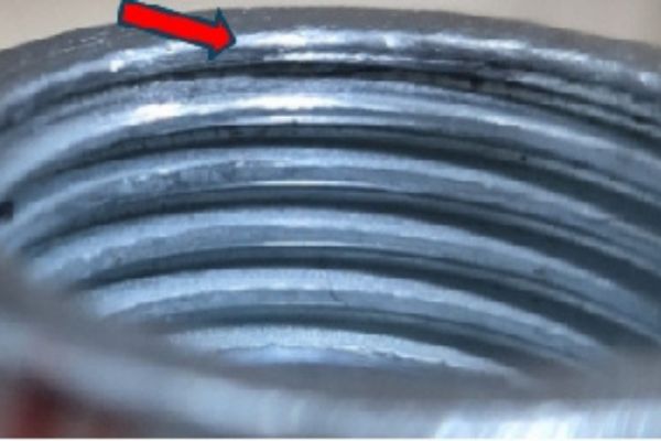
Read the edge in context
Chamfers, radii, thread lead-ins, wrench-flat transitions, and controlled edge breaks may all be deliberate. Their presence, size, and location should agree with the drawing or applicable specification. A rounded edge is not automatically acceptable if the drawing calls for another geometry, and a sharp corner is not automatically a burr if it is intentional and safely inspectable.
Use directed light and magnification to look for raised material, irregular continuity, folding, or a loose projection. Compare the suspect edge with nearby repeated features and with an approved reference when available. Do not decide by running a bare finger across it. That practice can cause injury, detach evidence, contaminate the part, or create an inconsistent tactile judgment.
Cosmetic appearance is not the governing test
A small discoloration away from any working interface may be cosmetic; a nearly invisible burr inside a port can be functional. Classify the edge by its relationship to a thread, seal, flow path, hose stem, ferrule, mating shoulder, or handling surface. This prevents inspectors from spending attention on harmless color variation while missing a particle source.
If no edge requirement exists and the feature’s effect is uncertain, document and escalate the condition. An informal rule such as “no sharp edges anywhere” is too vague to support repeatable acceptance and may conflict with required thread or sealing geometry.
Find Burrs Where Machining Operations Intersect
Burrs on one-piece hydraulic fittings frequently develop where a cutting tool enters, exits, breaks through, or crosses another machined feature. Inspection should therefore follow the manufacturing geometry even when the exact process route is unknown.
External and accessible locations
Common locations include thread starts, thread runouts, wrench flats, drilled ports, tube or hose-end features, sealing-face boundaries, grooves, and the edges of stamped or marked areas. A thread-start burr may fold during engagement. A ridge near a flare seat may contact the mating surface. A raised edge near a swivel component may interfere with movement or shed particles.
Rotate the fitting under controlled light rather than viewing it from only one angle. Low-angle illumination can show a shadow from a raised projection, while front lighting reveals torn or reflective areas. Magnification should preserve enough field of view to identify the exact location and orientation.
Internal intersections need a deliberate search
Cross-holes, intersecting passages, counterbores, and internal shoulders can retain burrs that are invisible from the opening. A drilling breakthrough may leave a crescent of material on the far side. A chip can remain attached by a thin root, survive casual air cleaning, and later detach in service.
Inspection access determines the method. Directed illumination, mirrors, optical scopes, or borescope-style equipment may be appropriate when the inspection plan supports them. The goal is to see the far edge and surrounding passage without inserting a tool that scrapes, pushes, or breaks off the feature before it is documented.
| Burr location | Main functional risk | Suitable inspection approach |
| Thread start or runout | False start, cross-threading, debris, damaged mating thread | Clean visual inspection, oblique light, magnification, specified thread gauge |
| Flare seat or sealing edge | Seal cutting, incomplete contact, leak path | Non-contact visual or optical review against drawing requirements |
| O-ring groove or lead-in | O-ring shaving, twisting, localized leakage | Magnified optical review and approved dimensional inspection |
| Cross-hole intersection | Particle release, flow disturbance, restricted passage | Directed internal light, mirror, scope, or validated borescope method |
| Internal bore or shoulder | Contamination, assembly interference, damaged inserted component | Optical access, cleanliness check, and feature-specific gauge when specified |
Understand the Risk at Threads and Seals
Burr severity depends on what the edge can touch and what can happen next. The same-looking projection carries different consequences on a noncontacting exterior and at an O-ring lead-in.
Thread burrs affect more than gauge fit
A burr on the start can prevent clean alignment and encourage forcing. A projection on a crest or flank can alter engagement, damage the mating part, or create particles. Coating buildup can resemble a burr but points to a different process; classify whether the raised condition is base metal, coating, embedded debris, or physical damage.
Clean the thread before gauging, align the correct ring or plug gauge, and apply only the permitted handling method. Never use force to “clear” a questionable thread. A gauge that engages does not prove that the sealing interface is correct, and a gauge failure does not prove a burr is the cause. Thread form, size, taper, coating, dirt, and gauge condition remain separate variables.
Sealing edges can damage elastomers or contact bands
An O-ring may be cut as it passes a raised lip. A metal-to-metal seat may fail to contact evenly if a projection holds the mating face away. A burr can also trap lint or metal particles that later enter the system. These risks make location and orientation as important as visible size.
Do not insert an O-ring as an improvised test. That can damage the seal and destroy evidence. Instead, compare the edge, lead-in, groove, and sealing surface with the current drawing and approved inspection method. Keep the seal material and application decision separate from the edge inspection.
Treat Internal Burrs as Cleanliness Risks
Internal burrs are difficult because access is limited and a loose feature can migrate. A part that looks clean at the opening may still carry attached chips or sharp breakthrough edges deeper in the passage.
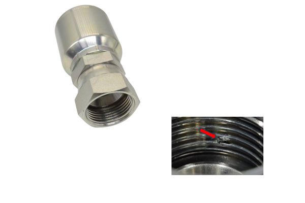
Inspect before aggressive cleaning or rework
Preserve the original condition when a complaint, incoming rejection, or process investigation is involved. Photograph the opening and accessible internal feature before brushing, flushing, deburring, or applying high-pressure air. An aggressive cleaning step can remove the evidence without proving that the rest of the batch is clear.
After documentation, follow the approved cleaning method and reinspect. Do not direct debris toward another cavity or leave fibers behind. If a scope enters the passage, protect the surface from contact and verify that the probe is clean. The equipment should reveal the condition, not change it.
Access limitations belong in the record
When the far side of an intersection cannot be seen, record the limitation rather than reporting “no burr found.” Sampling plans should account for difficult-to-view features, and engineering may require a validated indirect method, sectioned sample, process evidence, or another inspection approach.
Internal cleanliness and burr control overlap but are not identical. A loose chip can exist without a remaining burr, and a firmly attached burr can exist in an otherwise clean part. Report each condition separately so containment and corrective action address the correct failure mode.
Combine Visual, Optical, and Functional Methods
No single method finds every burr. A layered inspection starts broadly, narrows to suspect edges, and applies functional checks only where they answer the intended question.
Use non-damaging observation first
Begin with part identity, drawing revision, batch, and finish condition. Remove only loose surface contamination by an approved method. Examine the fitting under stable light, rotate it, and compare multiple viewing angles. Use magnification for classification and a mirror or scope for internal access.
Tactile inspection, when an approved tool and method exist, must not involve fingers or an improvised sharp probe. A swab or indicator can snag and leave fibers, so its suitability must be established for the feature and cleanliness requirement. Never turn a risky shop habit into a formal acceptance method simply because it is fast.
Let each functional check keep its boundary
A thread gauge checks specified thread characteristics. A dimensional gauge checks geometry. A cleanliness test addresses particles. A borescope supplies images. None independently measures every burr or establishes its functional effect. Combine results with the drawing and inspection plan rather than allowing one pass result to clear an unrelated feature.
If rework is permitted, define the method, material-removal limits, cleaning, coating restoration, and reinspection. Hand filing or scraping without controls can change a sealing angle, thread lead-in, wall thickness, or surface finish. Reworked parts need traceable disposition, not an undocumented visual touch-up.
Document and Contain a Burr Finding
A useful defect record lets another person find the same edge and understand why it was contained. “Burr present” is not enough for supplier review, batch sorting, or corrective action.
Capture location, form, and evidence
Record the part number, batch or lot, drawing revision, sample identity, finish condition, feature name, inspection method, and defect classification. Add an overview photograph that orients the fitting and a close-up that shows the edge. A scale reference should sit in the same plane when practical without touching the defect.
Describe whether the feature is raised, loose, folded, torn, continuous, isolated, or associated with a scratch or coating defect. State whether it is at a thread start, groove entry, cross-hole far edge, bore shoulder, or sealing boundary. Avoid estimating height or declaring a root cause unless the approved method supports that conclusion.
Prevent mixing while the decision is open
Segregate the affected sample and potentially related stock according to the quality procedure. Preserve labels, cartons, inspection records, and photographs. Do not return unknown or mixed batches to traceable inventory. If screening is authorized, use a defined feature list, sample or sorting scope, acceptance reference, and inspector qualification.
Containment is not proof that every part is defective, and traceability is not proof of conformity. It limits exposure while engineering or quality determines the requirement, extent, disposition, and any corrective action.
Follow a Repeatable Burr-Inspection Sequence
A consistent sequence reduces missed features and prevents the inspection itself from altering evidence. Adapt the sequence to the drawing and the fitting design.
Move from identity to release
- Confirm the part number, batch, drawing revision, material, coating, and sample identity.
- Map thread starts, sealing edges, grooves, cross-holes, bores, shoulders, stem features, and machined transitions.
- Preserve overview photographs before cleaning when the condition may support an investigation.
- Inspect accessible edges with controlled light and magnification; rotate the part through several angles.
- Inspect internal intersections with the approved mirror, scope, or indirect method and record access limits.
- Apply thread, dimensional, and cleanliness checks separately where the inspection plan requires them.
- Classify designed geometry, burrs, scratches, chips, and coating buildup as distinct findings.
- Contain questionable stock, link evidence to the batch, and obtain an approved disposition before rework or release.
The sequence is complete only when every required location has either a result or a documented access limitation. A quick exterior glance cannot clear hidden cross-holes, and a clean bore opening cannot clear a far-side breakthrough edge.
Conclusion
Reliable burr inspection depends on location, function, and controlled evidence. Designed chamfers and edge breaks must be separated from raised, torn, or loose material, while threads, sealing interfaces, grooves, bores, and cross-holes must be reviewed for their distinct risks. Use safe lighting and optical access before any cleaning or rework that could remove evidence, and never slide fingers across suspected sharp edges. Gauge results, cleanliness checks, and photographs each answer only part of the question. Preserve the original condition long enough to support classification and containment. Before releasing a batch after one-piece fitting burr inspection, confirm the current drawing, inspected locations, access limitations, defect records, containment scope, approved acceptance criteria, and any required reinspection after correction.
Frequently Asked Questions
How can internal burrs be inspected when the bore is narrow?
Use the approved optical or indirect method that can reach the feature without altering it. Directed light, mirrors, or a suitable borescope may help, but inaccessible areas and image limitations must be recorded.
Is a sharp thread start always a burr?
No. The thread lead-in and edge geometry must be compared with the drawing and thread requirement. Raised or displaced material is a different condition from a correctly formed intentional start.
Can a small burr damage a hydraulic seal?
It can if it lies on the seal’s installation path or contact area. Functional risk depends on location, orientation, attachment, and the specified geometry, not on an assumed universal burr height.
Does a borescope prove that an internal passage is burr-free?
Not necessarily. Image quality, viewing angle, access, lighting, and hidden intersections limit what it can prove. Record the coverage and combine the images with the approved inspection plan.
Can a fitting be reworked after a burr is found?
Only under an approved method and disposition. Rework must control material removal, cleanliness, geometry, coating restoration, and reinspection so correcting the burr does not create a different defect.