Not every surface on a hydraulic fitting needs the same finish. A one-piece fitting surface finish must be judged by what that surface does: create a seal, guide an O-ring, carry thread load, accept plating, control flow, or simply form the exterior. Treating all visible marks as equal can reject harmless tool patterns while missing a scratch across a sealing path.
Start With the Surface Function, Not Its Appearance
The first inspection question is not “Does this look smooth?” It is “What must this surface do in the finished connection?” That question determines whether texture, direction, edge condition, geometry, or coating integrity matters most.
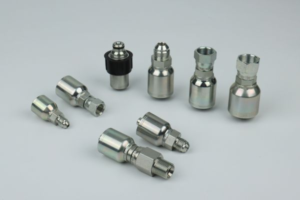
Functional surfaces carry a defined job
A flare seat or cone may form a metal-to-metal sealing contact. An O-ring groove controls seal position and compression. Thread flanks transfer load and guide engagement. An internal bore affects cleanliness and flow, while a machined transition may influence stress concentration. Each function exposes the surface to a different failure mechanism, so one visual standard cannot sensibly cover them all.
The controlled drawing should identify critical geometry and any finish requirement. Reviewers should connect each callout to the actual feature rather than applying a general note blindly. If the drawing specifies a roughness requirement but its leader or scope is unclear, request clarification before accepting or rejecting parts. Guessing which surfaces a note covers creates inconsistent inspection.
Noncritical exteriors still have boundaries
An exterior wrench flat or body surface may not contact a seal, but it can still require adequate preparation for plating, safe handling, corrosion protection, marking, or identification. A shallow, uniform tool pattern on such a surface may have little functional consequence; a raised burr, flaking coating, deep gouge, or damage that reaches a transition is different.
Calling an area “cosmetic” should never be a shortcut for ignoring it. The classification must come from the product drawing, purchase specification, and intended use. If an exterior defect could trap contamination, interfere with a wrench, expose base material, or obscure a part mark, it has an operational consequence even when it is outside the primary sealing interface.
| Surface | Main function | Likely defect of concern | Appropriate verification approach |
| Flare or cone seat | Establish sealing contact | Crossing scratch, dent, chatter, coating buildup | Controlled light, magnification, profile or dedicated method from the drawing |
| O-ring groove | Locate and support the seal | Burr, sharp edge, wrong texture, embedded debris | Visual and magnified inspection plus specified dimensional verification |
| Thread flank and start | Guide engagement and carry load | Torn material, burr, damaged crest, coating interference | Clean inspection, magnification, and the specified functional gauge |
| Internal bore or cross-hole | Provide flow path and cleanliness | Loose chip, internal burr, smeared material | Directed illumination, suitable optical access, and cleanliness checks |
| Coated exterior | Protect and identify the part | Blister, bare area, staining, poor adhesion | Visual comparison and specified coating tests or records |
Treat Sealing Faces as Contact Geometry
A sealing face matters because another component, an elastomer, or both must contact it in a controlled way. Finish review therefore belongs with geometry, cleanliness, and damage inspection rather than with appearance alone.
Direction and location of a mark change the risk
A scratch that crosses the expected sealing path can create a leakage route. A mark outside the contact band may be less important, but only if the contact location is known. Circular, radial, or irregular marks can interact differently with the seal, and a reviewer should not infer acceptability from length or visibility without a defined criterion.
Machining marks may be a normal result of the specified process. Their pattern should be evaluated against the drawing requirement and the intended contact. Chatter, torn material, a dent, or a localized ridge is not the same as a consistent lay. The inspection record should describe where the condition sits relative to the sealing band, not merely state “scratch on face.”
Roughness does not replace profile and geometry checks
Ra is an arithmetic roughness parameter that summarizes height variation over an evaluated trace. It does not, by itself, reveal every deep isolated scratch, waviness, incorrect angle, eccentric seat, or raised burr. Two surfaces can produce similar Ra results while presenting different sealing risks.
Use the parameter and measurement setup specified by the drawing or inspection plan. Instrument cutoff, trace direction, access, surface curvature, and cleanliness can affect the result. A portable reading taken on the wrong area should not override visible localized damage or a failed geometry check. Where the surface is too small or inaccessible for a reliable direct measurement, use the approved comparison or dedicated inspection method rather than inventing a number.
Inspect O-Ring Grooves Without Damaging Them
An O-ring groove combines dimensional control with surface condition. The seal must enter, move, and remain in the groove without being cut, twisted, pinched, or exposed to a leakage path.
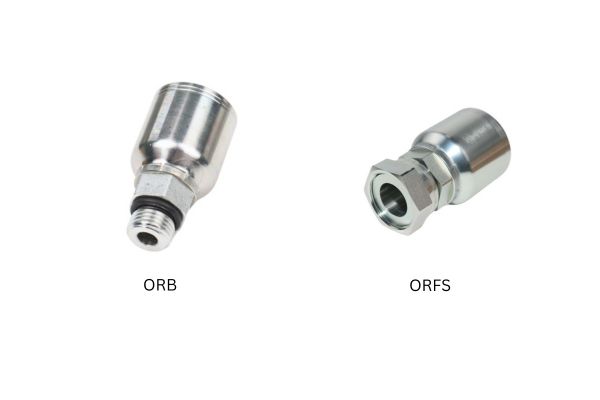
Groove edges and walls have different concerns
An entry edge may need a controlled break or lead-in, while the groove wall and bottom may carry specified finish requirements. A designed radius or chamfer is not a burr. Conversely, a thin fin of displaced metal is not acceptable merely because it follows the edge. Compare the feature with the drawing before classifying it.
Inspect for embedded chips, coating buildup, corrosion, torn material, and sharp projections. Do not drag a fingernail, pick, or unapproved probe across the groove. Touch-based approval can miss small defects and may add a new scratch. Use safe optical methods and non-damaging dimensional tools selected for the feature.
Read Thread Surfaces as a Functional System
Thread inspection should distinguish surface condition from thread form, pitch, diameter, taper, and class. A smooth-looking thread can be dimensionally wrong, while a visible manufacturing pattern can still function if it conforms to the specified requirements.
Starts, crests, roots, and flanks deserve separate attention
The thread start is vulnerable to handling damage and incomplete deburring. A raised edge can obstruct initial engagement or shed a particle. Flanks carry engagement load and need freedom from torn metal, dents, or coating buildup that changes fit. Roots and crests may show process marks, but their condition must be assessed with the specified thread standard and drawing.
Clean the thread before using a functional gauge. Dirt, dried preservative, loose plating debris, or chips can create a false failure and can damage the gauge. Align the gauge correctly and never force it. Gauge results address defined thread characteristics; they do not certify the sealing face, seat angle, or hose-end compatibility.
Plating changes the inspected surface
If the finished thread is plated, acceptance normally concerns the finished condition unless the specification says otherwise. Excess buildup, bare spots, blisters, or displaced coating can affect engagement and corrosion protection. A pre-plating measurement is useful process information but cannot automatically substitute for final inspection.
Document whether the finding was observed before or after coating. This distinction helps separate a machining defect reproduced through the coating from a coating defect created later. It also prevents rework decisions based on the wrong stage of manufacture.
Separate Machining Marks, Scratches, and Burrs
These terms describe different physical conditions and should lead to different questions. Mislabeling them weakens both inspection records and corrective action.
Identify the physical feature before judging it
A machining mark is a pattern produced by a cutting or finishing process. Roughness describes fine-scale texture using a defined parameter and method. A scratch is localized damage made by contact or movement after or during processing. A burr is raised or displaced material at an edge or intersection. A dent removes no material but changes local shape, while a coating defect belongs to the applied layer.
Use lighting from more than one angle because a shadow can reveal raised material that flat lighting hides. Magnification can help classify the edge, but greater magnification is not automatically better; the field of view must still show the feature’s location. Never run a bare finger across a suspected burr or sharp thread start. A controlled visual or optical method is safer and more repeatable.
Classification guides containment and correction
A random scratch may point to handling, tray contact, or metal-to-metal packing. Repeated directional chatter may point to process stability or tool condition. Burrs at every cross-hole indicate an edge-finishing problem. Blisters or peeling indicate a coating process or surface-preparation problem. These observations help contain the right batch and process step without claiming a root cause from one part alone.
Record the defect type, exact feature, orientation, extent, coating condition, part number, batch, and inspection method. Include an overview photograph and a close-up with scale when practical. Do not polish, lap, deburr, or touch up a functional surface until the applicable rework method and reinspection requirement are approved.
Connect Surface Preparation to Plating Quality
Plating and other finishes reproduce or sometimes emphasize the base surface beneath them. They can protect a fitting, but they cannot reliably convert damaged geometry into an acceptable functional surface.
Base material condition affects the finished layer
Oil, oxide, embedded debris, smeared metal, deep tool marks, or residual burrs can interfere with cleaning, coverage, and adhesion. Coating may bridge a small recess, collect at an edge, or leave a thin area on a projection. The visual result must therefore be examined together with the underlying feature and the coating specification.
Do not use a corrosion test result as proof that every surface on every part is defect-free. A test report applies to its stated samples, preparation, method, and acceptance criteria. Likewise, a thickness reading at one accessible location does not establish thickness or adhesion everywhere. Link the record to the correct SKU, finish, batch, and revision.
Finished sealing areas require explicit review
Some designs protect certain sealing surfaces from coating; others define an acceptable finished condition. Never assume that bright, uniform color means the sealing face is correct. Coating buildup, masking boundaries, stains, bare spots, or particles can still affect contact or cleanliness.
When a drawing is unclear about coating on a seat, thread, or groove, stop approval and clarify the intended finished state. A supplier, inspector, and buyer cannot apply a consistent standard when one party judges the machined surface and another judges the coated surface.
Choose Inspection Methods That Match the Question
Inspection becomes reliable when each method answers a defined question. Visual review, comparison specimens, stylus instruments, optical systems, dimensional tools, and functional gauges are not interchangeable.
Build a layered inspection
Begin with cleanliness and an overview under controlled light. Locate functional surfaces, then use magnification to classify localized conditions. Apply the specified roughness or profile method only where the geometry and access support a valid measurement. Complete relevant dimensional, seat, or thread checks separately.
A practical review sequence is:
- identify the part number, drawing revision, batch, and finished condition;
- map each sealing, guiding, threaded, flow, coated, and exterior surface;
- remove loose contamination using an approved method without altering evidence;
- inspect for scratches, burrs, dents, chatter, corrosion, and coating defects;
- measure roughness only with the specified parameter, setup, and location;
- record uncertain or inaccessible features for engineering clarification.
Avoid unsupported acceptance decisions
Touch alone is not an inspection method for sealing faces. A photograph alone rarely provides calibrated roughness or depth. A single Ra value does not clear a crossing scratch. Conversely, a visible tool pattern is not automatically a reject when it meets the controlled specification and does not create a localized defect.
If no acceptance criterion exists, document the condition and escalate it. Creating an informal shop-floor limit may feel efficient, but it disconnects receiving decisions from the drawing and can produce different answers for identical parts.
Surface-by-Surface Review Checklist
Release should depend on traceable requirements and feature-specific evidence. Use this checklist to organize the review, then apply the actual drawing and inspection plan.
Confirm the requirement and the evidence
- Verify part number, drawing number, revision, material, and finish condition.
- Mark the flare seat, sealing face, O-ring groove, thread, bore, cross-hole, transition, and exterior areas that apply.
- Identify which surfaces have explicit roughness, coating, edge, or geometry callouts.
- Describe defects as machining marks, scratches, burrs, dents, contamination, corrosion, or coating defects.
- Record defect location relative to the contact path, not only its appearance.
- Use the specified instrument, comparator, gauge, lighting, and sampling plan.
- Link photographs and readings to the inspected batch and individual sample.
- Quarantine uncertain parts without mixing them into accepted stock.
The checklist does not create acceptance values. It ensures that the right question reaches the right requirement owner. When the drawing, inspection plan, and finished part disagree, clarification is safer than relying on memory, touch, or a generic “looks good” standard.
Conclusion
Surface-finish review is reliable only when it begins with function. Sealing seats, O-ring grooves, threads, bores, coated exteriors, and machined transitions face different risks, so they cannot share one visual rule or one assumed Ra value. Inspectors should classify the physical condition, locate it relative to the working interface, and use the drawing’s specified method and acceptance criteria. Roughness data cannot erase a scratch, a thread gauge cannot approve a seat, and uniform color cannot prove coating adhesion or geometry. A clean visual result also cannot replace the required dimensional or coating evidence. Before approving a one-piece fitting surface finish, prepare the current drawing revision, surface map, batch identity, finished condition, inspection method, and clear defect records for every functional area.
Frequently Asked Questions
Does every one-piece fitting surface need an Ra value?
No. A roughness value is needed only where the controlled drawing or specification requires it for the surface’s function. Other areas may be governed by geometry, edge condition, coating, cleanliness, or visual defect criteria instead.
Is any scratch on a sealing face a rejection?
Not automatically, but it requires evaluation against the defined sealing contact and acceptance criteria. Its location, direction, depth, raised edges, and effect on geometry matter, and touch alone cannot approve it.
Can a thread gauge detect poor thread surface finish?
A functional gauge can reveal some engagement problems, but it does not characterize every surface defect. Clean visual inspection should accompany gauging, and the specified thread standard determines acceptance.
Does good plating hide an unacceptable machined finish?
No. Plating may reproduce, emphasize, or partly bridge underlying features, but it does not correct wrong geometry, burrs, or sealing damage. Inspect the finished surface and retain evidence of the relevant base condition when required.
Is visual inspection enough for hydraulic fitting surface roughness?
Usually not when a numerical roughness requirement is specified. Visual inspection can locate and classify defects, while the approved measurement or comparison method confirms the controlled finish requirement.