Two inspectors can measure the same finished ferrule and record different values when they use different locations, instrument pressure, orientations, or treatment of ridges. To measure crimp diameter on one-piece hose fittings consistently, the inspection method must define the correct measurement zone, suitable calibrated instrument, required circumferential positions, and acceptance source before anyone takes a reading. The measured value then has to be linked to the exact hose, fitting, machine setup, and approved crimp data. This is a metrology task, not a way to invent a target dimension or approve an unidentified assembly.
Start With the Governing Measurement Instruction
The first question is not which number appears on the instrument; it is which controlled document defines what to measure. A crimp diameter has meaning only when the measurement location and method match the acceptance data for the exact assembly.
Confirm the assembly identity
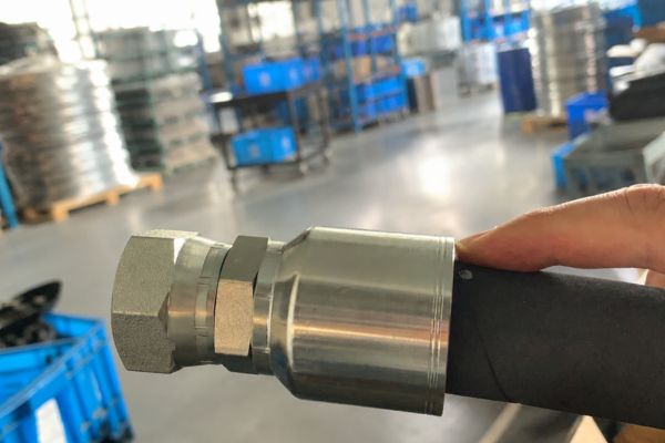
Record the hose manufacturer, hose series, construction, size, complete fitting code, fitting series, and ferrule design. Confirm the work traveler and the revision of the crimp specification. The same dash size does not authorize using a target or method from another hose series, fitting family, or brand combination.
Also confirm that the assembly is safe to handle. Do not measure a connected, pressurized, leaking, or otherwise hazardous assembly. Isolate the hydraulic system, release pressure and stored energy, secure raised loads, and follow the applicable equipment and component procedures before removing or inspecting field hardware.
Read the method, not just the target
Approved data may define where along the ferrule to measure, how many readings to take, whether particular orientations are required, which surfaces are excluded, and how results are evaluated. A target dimension copied without those instructions can produce a false comparison. The drawing or crimp chart may also distinguish different ferrule zones or product constructions that look similar from a distance.
If the measurement location, instrument type, or acceptance rule is missing, place the result on hold. Do not choose the smoothest area, average convenient readings, or borrow a method from a neighboring SKU to make the inspection possible.
Before measurement, confirm this minimum evidence set:
- Exact hose and fitting identities
- Current crimp specification and measurement-zone definition
- Approved instrument type and valid metrology status
- Required reading positions and decision rule
Locate the Correct Crimp Measurement Zone
Measurement location is a controlled characteristic because ferrule geometry is not necessarily uniform along its length. Readings taken near an end, transition, groove, or local feature may not represent the zone used to establish the approved crimp data.
Establish axial position from a defined reference
Use the reference identified in the applicable instruction, such as a ferrule edge, shoulder, band, or drawing-defined location. Keep the instrument contacts within the stated zone and square to the ferrule axis unless the method specifies otherwise. Marking the zone with a removable, approved method can help repeatability, but the mark must not damage the surface or obscure a defect.
Avoid measuring partly on a taper, end flare, step, raised marking, damaged patch, or coating buildup unless that feature is explicitly included in the method. Even a small axial shift can place the contacts on a different part of the crimp profile and create an apparent disagreement between inspectors.
Control the part’s condition and support
Clean loose debris only as the approved procedure permits. Do not file, polish, compress, or reshape ridges to obtain a stable reading. Support the assembly so its weight does not tilt the instrument or pull the hose against the ferrule while the reading is taken.
The hose should rest without twist or forced bending near the fitting. Inspectors should also note visible impact, cracked plating, displaced components, or other conditions that may invalidate routine measurement and require a separate disposition.
Select and Verify the Measuring Instrument
Use an instrument capable of contacting the specified surfaces and resolving the required acceptance range. Instrument choice should come from the inspection plan, measurement-system evaluation, or technical procedure—not from whichever tool is nearest.
Match contact geometry to the ferrule
Calipers may be suitable for some defined checks, while other geometries or accuracy requirements may call for a micrometer or a dedicated device. Broad, narrow, flat, or shaped contacts interact differently with crimp ridges and valleys. A tool that bridges high points can report a different functional dimension from one whose contacts fall between them.
The selected instrument must be able to reach the measurement zone without contacting the hose, fitting body, ferrule end, or adjacent feature. Do not angle the jaws to fit into a restricted area. If the required contacts cannot sit correctly, the instrument or inspection setup is unsuitable for that measurement.
Confirm instrument status and technique
Check the instrument identifier, current calibration or verification status, cleanliness, zero condition, range, resolution, and physical condition according to the local metrology system. Close the contacts with consistent measuring force. Excessive force can deflect the instrument, mark a soft surface, or create operator-dependent readings.
Before recording production results, inspectors should be able to repeat a reading on a suitable reference or training piece within the shop’s accepted method. If two instruments disagree, do not average their outputs. Isolate the issue by checking zero, condition, contact placement, method, environment, and metrology status.
Control Orientation and Circumferential Readings
A single reading can miss out-of-round geometry or exaggerate a local ridge. Follow the exact number and orientation of readings specified by the approved crimp procedure.
Keep the instrument perpendicular
Place the contacts across the ferrule with the measurement axis passing through the intended diameter. Keep the instrument square to the fitting axis and avoid rocking it diagonally. A skewed position measures a chord or diagonal rather than the required diameter and often produces a larger, unstable result.
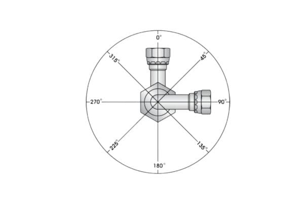
Rotate around the ferrule only through the positions allowed by the instruction. When specific clock positions are defined, establish a repeatable reference such as the fitting orientation, machine seam, or a controlled mark. When the procedure calls for multiple evenly distributed readings, do not concentrate them on the easiest exposed side.
Record individual values before calculating anything
Write each reading as observed, with its position, before applying any specified calculation or decision rule. Do not erase the highest or lowest value because it appears inconvenient. Variation between positions can be evidence of die condition, component placement, debris, asymmetric setup, or measurement error.
Use an average, range, maximum, minimum, or other derived value only if the governing procedure requires it. A calculated average may conceal one unacceptable position when each reading has an individual limit. Conversely, rejecting solely on spread without an approved out-of-round criterion can create an unsupported decision.
Interpret Ridges, Flats, and Out-of-Round Indications
Finished crimp geometry reflects the ferrule, die segment pattern, process, and material response. Visible ridges do not tell an inspector where the approved diameter is defined, and a smooth appearance does not prove conformity.
Distinguish normal pattern from measurement interference
Segment impressions, narrow ridges, flats, or transitions may be expected for a particular controlled process, but their acceptability must come from the applicable specification or approved visual standard. Position the contacts as instructed relative to those features. Do not hunt for the lowest diameter or deliberately bridge the highest points unless the method says to do so.
Surface finish can also affect contact. Dirt, burrs, coating damage, dents, or raised marks may produce unstable readings and may represent a separate defect. Record the condition and follow the nonconformance process rather than modifying the surface or choosing another area without authorization.
Treat inconsistent diameters as a diagnostic signal
When readings differ more than expected under the approved method, first repeat the measurement with controlled placement and technique. If variation persists, hold the assembly and review instrument condition, measurement zone, die cleanliness and condition, die seating, component position, machine setup, and part identity.
Do not assume that an out-of-round indication can be corrected by recrimping. Any additional crimp operation requires explicit manufacturer or process authorization for the exact assembly. A second operation may further compress or damage the hose, ferrule, or reinforcement while hiding the original cause.
Compare Results With the Correct Acceptance Data
The right comparison is between traceable readings and the current acceptance rule for the exact controlled combination. A historical spreadsheet, handwritten value, or chart for another SKU cannot release the assembly.
Verify scope and revision
Confirm that the crimp record names or unambiguously covers the hose series, hose size, fitting family, ferrule, preparation method, machine or process basis, and applicable revision. Review any notes that modify the target by product variant or measurement location. If the shop uses electronic programs, verify that the document and program revision agree.
Classify the result using the procedure’s defined outcome: acceptable, hold for clarification, or nonconforming. Do not invent a tolerance around a target that has no published acceptance range. Likewise, do not convert an approximate setup value into a finished-product criterion.
Escalate ambiguity without losing evidence
When the source data conflict, preserve the assembly, readings, instrument identity, setup record, and documents used. Ask the responsible technical or quality authority to identify the governing revision. Do not repeatedly measure until one reading falls inside the preferred range.
If the method itself appears difficult to reproduce, raise a measurement-system concern. A process cannot be controlled reliably when inspectors use different contact points or interpretation rules. The corrective response may involve clearer drawings, a fixture, improved training, or a formal measurement-system study rather than changing the product.
For an ambiguous result, preserve:
- Every original reading and its position
- Instrument identifier and status
- Photographs or notes showing the contact location
- Machine, tooling, setup, and component-lot records
- Conflicting document numbers and revisions
Use a Complete Inspector Measurement Record
A useful record lets another qualified person reconstruct the measurement and determine which batch or setup it supports. Blank fields should trigger clarification rather than quiet assumptions.
| Record field | Information to capture |
| Assembly identity | Hose manufacturer, series, size, fitting SKU, ferrule, component lots |
| Process identity | Machine, dies or tooling, program or setup, work order, operator |
| Governing data | Crimp specification, drawing or instruction number, revision, measurement zone |
| Instrument | Type, identifier, resolution, calibration or verification status |
| Measurement conditions | Date, inspector, part condition, axial location, orientation reference |
| Readings | Every required position and observed value; required calculation, if any |
| Decision | Accepted, held, or nonconforming; acceptance source and reviewer |
| Follow-up | Discrepancy, containment, recheck basis, and final disposition reference |
Attach photographs only when the procedure needs them, and include a clear orientation or datum. A photograph of an instrument display without the contact location, assembly identity, and source data is weak evidence. Keep the record with the batch or hose-assembly genealogy defined by the quality system.
Conclusion
Consistent crimp measurement begins with the approved method for the exact hose-and-fitting combination. Confirm identity and revision, locate the drawing-defined measurement zone, use a suitable controlled instrument, keep the contacts square, and capture every required circumferential reading before calculating a result. Ridges, flats, surface damage, and out-of-round indications must be interpreted through the applicable procedure rather than personal preference. Compare observations only with current acceptance data and hold the assembly when the method, source, or instrument is uncertain. A complete record should link the values to the component lots, machine, tooling, program, instrument, inspector, and disposition. That discipline is how inspectors reliably measure crimp diameter on one-piece hose fittings without inventing a universal range.
Frequently Asked Questions
Can a caliper always be used to measure crimp diameter?
No, instrument suitability depends on the required accuracy, contact geometry, ferrule features, and approved method. Use the instrument specified or accepted by the controlling inspection procedure.
Should the smallest circumferential reading be reported?
Only if the approved method defines that decision rule. Record all required individual readings and apply the specified maximum, minimum, average, or position-based criteria without selecting a convenient value.
Can a reading be taken over a die ridge?
That depends on how the controlled method defines the contact position relative to the crimp pattern. Do not bridge or avoid ridges based on personal preference.
What should happen if two inspectors disagree?
Place the result on hold and compare assembly identity, axial location, orientation, contact force, instrument status, and method interpretation. Do not average the inspectors’ results unless the procedure explicitly requires it.
Does an acceptable diameter prove the hose was inserted correctly?
No, diameter is only one characteristic of the completed assembly. Hose identity, preparation, insertion, fitting identity, tooling, setup, condition, and other required checks still need independent confirmation.