An elbow can have the correct thread, sealing method, and hose size yet physically fail to fit beside a neighboring port, cover, frame, or tool path. Checking installation clearance for one-piece elbow fittings requires a dimensioned three-dimensional envelope, not a catalog angle alone. Define the connection datum, elbow centerline, drop, sweep, overall projection, ferrule and hose tangent, then compare that shape with fixed obstacles and equipment movement. Confirm final orientation, wrench access, hose bend requirements, and assembly removal space. Use symbolic dimensions until controlled product and machine drawings supply actual values; never force the hose to compensate for missing clearance.
Reconstruct Why the Elbow Will Not Fit
When a replacement elbow contacts a guard or blocks another connection, the mismatch should be treated as a geometry problem. Tightening harder, rotating beyond the allowed position, or bending the hose more sharply does not correct the product envelope.
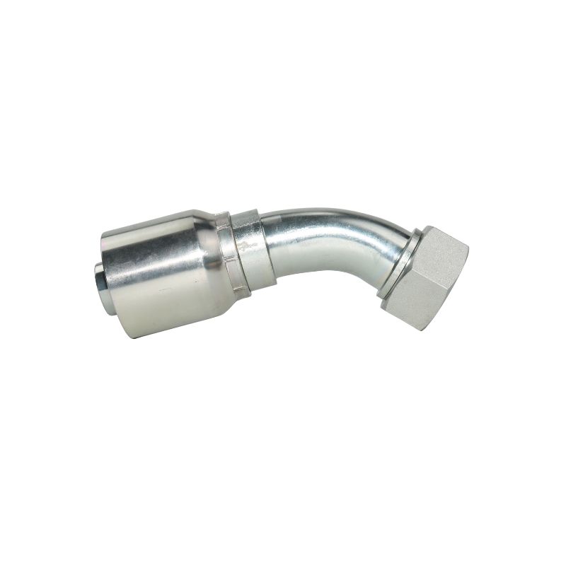
Preserve the failed-fit evidence
Record the fitting code, hose identity, port location, mating connection, attempted orientation, and exact contact point. Photograph the complete installation from more than one view with a scale and identify which surfaces are fixed, removable, or moving. Keep the old fitting and assembly drawing when available.
Do not judge clearance while the circuit is pressurized or a load can move. Stop the equipment, isolate hydraulic pressure, release stored energy, secure raised or suspended loads, and follow lockout and equipment procedures before measuring near ports or moving structures.
Separate interface fit from envelope fit
First verify the thread form, diameter, pitch or TPI, straight or tapered condition, seat, seal, and mating interface. Then evaluate the external geometry. A fitting that threads in is not automatically the correct connection, and a correct connection is not automatically the right elbow shape.
Record whether interference occurs at the nut, flange head, body, elbow arc, ferrule, hose tangent, clamp, or tool. That location determines which dimension or orientation needs clarification.
Define the Elbow With Symbolic Dimensions
A labeled drawing prevents vague terms such as “short elbow” or “more drop” from being interpreted differently. The exact dimension convention must follow the controlled fitting drawing, but a symbolic model organizes the fit check.
Establish datums and centerlines
Let datum P represent the functional connection plane defined by the fitting or port drawing, not simply the visible end of the thread. Let axis A be the port centerline and axis H the outgoing hose or stem centerline. Their intersection or drawing-defined elbow center provides a repeatable geometric reference.
Use symbolic dimensions such as:
- L1: distance from datum P to the elbow center along port axis A
- L2: offset from port axis A to hose centerline H
- E1: maximum projection of the connection and body from datum P
- E2: maximum lateral envelope of the elbow body and ferrule
- T: location where the flexible hose leaves the rigid fitting geometry
- R: drawing-defined elbow sweep or centerline radius, when provided
- W: required wrench, clamp, or installation-tool envelope
These symbols are not standard universal labels. Replace them with the manufacturer’s drawing terminology and actual controlled values during review.
Distinguish drop, sweep, and overall size
Drop or centerline offset locates the outgoing hose path relative to the connection. Sweep describes the curved transition or centerline geometry when the drawing defines it. Overall dimensions may include threads, swivel nuts, bodies, stems, and ferrules without directly locating the hose centerline.
Two 90-degree fittings can share an overall length but have different drops, or share a drop while having different body projections. Compare several functional dimensions instead of searching for one “height” value.
Map Adjacent Ports, Hose Exit, and Tool Access
The fitting envelope must coexist with other installed components and with the process used to assemble them. A final-position drawing that omits the wrench or clamp path can approve a connection that cannot actually be tightened.
Build the local equipment envelope
From the port datum, locate adjacent ports, fittings, valves, covers, brackets, fasteners, electrical components, heat sources, edges, and removable panels. Show the space occupied by those items and any assembly sequence constraints. If neighboring fittings are installed first, their bodies or hoses may block rotation and tool access for the elbow.
Check clearance around the connection, body, ferrule, hose tangent, and first bend. Include space to place and move the specified wrench, flange clamp, fastener tool, or backup wrench without using the hose as a handle.
Protect the hose departure
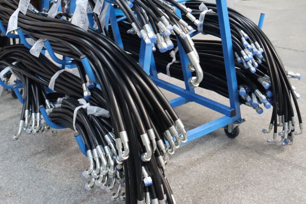
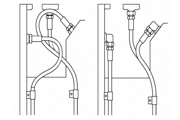
The hose needs a workable route after point T. Compare the proposed tangent direction with the hose manufacturer’s minimum bend radius, any required straight section near the fitting, torsion limits, clamps, abrasion protection, and movement allowance. Do not force an early bend to clear an obstacle.
A shorter elbow may reduce metal projection while crowding the hose against the port block. A longer elbow may improve the first bend but interfere with another component. The decision must include both rigid fitting geometry and flexible hose behavior.
Separate Installation Clearance From Operating Clearance
Installation clearance answers whether the fitting can be placed, oriented, tightened, and removed. Operating clearance answers whether the complete assembly remains clear under pressure response, vibration, temperature, and equipment motion.
Check assembly and service access
Model the path needed to insert the fitting, rotate a threaded or swivel element as designed, place seals or clamps, engage tools, and apply the approved installation procedure. Include future inspection and removal. A cover that can be removed may solve one step, but document that required sequence and confirm it is practical and safe.
For two nearby elbows, check whether one must be installed before the other and whether that sequence still permits correct orientation and tightening. Do not leave a connection partly loose merely to preserve access.
Check movement through the operating range
Identify moving cylinders, linkages, booms, guards, suspension components, articulated joints, and hose bundles. Compare the assembly envelope at every relevant equipment position using an approved safe method. Account for hose movement, growth, vibration, and support requirements from current design data.
A visible static gap is not automatically sufficient operating clearance. Do not invent a universal gap or tolerance; define required separation through the equipment design, component instructions, motion analysis, and risk assessment.
Verify Orientation and Rotation Without Guessing
Elbow direction is a three-dimensional requirement. “Pointing up” or “same as the old one” is unreliable unless the drawing defines the viewing direction and angular datum.
Specify clocking from a controlled view
Choose a datum feature on the port, flange, fitting connection, or equipment and state the direction from which orientation is viewed. Define the hose centerline angle relative to that datum. For a two-ended hose assembly, include the relative angular orientation of both ends and the finished-length reference.
If a female swivel nut permits installation rotation, distinguish nut movement from rotation of the complete elbow in service. If the elbow orientation locks as the connection is tightened, confirm that the approved installation method reaches both sealing condition and required direction.
Test the proposed outline before assembly
Overlay controlled fitting geometry on the equipment drawing or use an approved physical template, CAD envelope, or representative nonfunctional model. Include E1, E2, T, W, the hose bend corridor, and neighboring items. A screenshot without scale or datums is not a fit check.
Do not use a finished hydraulic assembly as the first template when interference could require force or damage. Resolve unclear geometry before crimping when possible, because changing the elbow later can also change hose cut length and end orientation.
Request Drawings and Measurements That Can Be Compared
Both original and proposed fittings should be described from the same functional references. Mixing catalog dimensions based on different datums can create a false mismatch or false approval.
Fitting and interface package
Request the complete product drawing and revision, connection standard, male or female configuration, thread and seal details, fitting angle, port datum, L1 and L2 equivalents, E1 and E2 equivalents, body and ferrule outline, hose tangent T, orientation features, and tool-access information. Add the exact fitting series, hose side, stem, and retained ferrule.
For an old part, take orthogonal photographs and measurements from labeled datums, but identify wear or damage that may affect the result. A photo alone cannot establish hidden geometry, thread pitch, seat angle, or dimensional scale.
Equipment and hose-route package
Provide the port drawing, neighboring-port locations, surrounding obstacles, removable covers, installation sequence, tool envelope, motion range, hose supports, first clamp, required bend data, finished assembly length definition, and relative end orientation. Mark the contact point that triggered the review.
Also provide hose manufacturer, series, construction, size, and current fitting and crimp compatibility information. A dimensional pass does not approve the hose-and-fitting combination or the port sealing interface.
Apply Pass, Clarify, or Reject Decision Points
Use a decision record rather than a verbal “should fit” judgment.
| Decision | Evidence condition | Action |
| Pass | Connection, symbolic dimensions replaced by controlled values, orientation, tool path, hose route, and motion envelope all satisfy requirements | Release the exact configuration and drawing revision |
| Clarify | No confirmed conflict, but a datum, dimension, movement condition, tool path, or source revision is missing | Hold and request the named evidence |
| Reject | Verified interference, forced hose routing, unavailable tool access, wrong interface, or operation outside documented limits | Select a different geometry or redesign through approved authority |
Do not convert “clarify” to “pass” because the order is urgent. Document who reviewed the fit, which drawings were compared, assumptions that were resolved, and which product and equipment revisions the decision covers.
Before requesting a clearance review, prepare:
- Labeled port and hose centerlines with functional datums
- Elbow drop, sweep, body, ferrule, and overall envelope fields
- Installed orientation and viewing direction
- Adjacent components, port spacing, cover, and tool envelope
- Hose tangent, bend corridor, clamps, and finished-length references
- Static and moving equipment positions
- Product, port, hose, and crimp document revisions
- Photographs tied to dimensions and unresolved questions
Retain the approved envelope with the assembly record so later replacements can be checked against the same geometry. The record should identify whether the review covered only installation, the full motion range, or both. If a cover, adjacent valve, clamp, hose bundle, or tool changes, repeat the affected portion of the fit check rather than assuming the original pass still applies. The same is true when a replacement fitting keeps the connection code but changes body shape, swivel length, ferrule, or elbow centerline. A controlled outline and decision history reduce repeat measurement while preventing an old approval from being applied to a physically different configuration.
Conclusion
Elbow clearance is a three-dimensional compatibility check, not a thread-and-angle comparison. Define a functional port datum, centerlines, drop, sweep, body and ferrule envelope, hose tangent, and tool space with symbolic dimensions, then replace those symbols with controlled drawing values. Compare the rigid fitting and flexible hose route with adjacent ports, covers, installation sequence, service access, and every relevant equipment position. Specify orientation from a named view and do not rely on a swivel nut, forced bend, or loose connection to correct interference. Use pass, clarify, or reject outcomes that preserve the reviewed revisions. For installation clearance on one-piece elbow fittings, prepare the dimensioned fitting outline, equipment envelope, hose-routing data, photographs, and unresolved fields before crimping or ordering.
Frequently Asked Questions
Does the correct port thread mean an elbow will fit?
No, thread and seal compatibility do not prove body, ferrule, hose, tool, or motion clearance. Review the complete three-dimensional envelope and orientation.
Is elbow drop the same as overall fitting length?
No, drop usually locates a centerline from a defined datum, while overall length can include several features. Use the exact drawing definitions for both products.
Can the hose be bent more sharply to clear a cover?
No, do not force routing below the hose manufacturer’s requirements or add twist near the fitting. Select suitable geometry or redesign the route through an approved process.
Should clearance be checked only with the equipment parked?
No, static installation and service access are only part of the review. Check relevant operating positions and hose movement through an approved safe method.
Can photographs replace an equipment drawing?
No, photographs help document obstacles and orientation but can distort scale and hide depth. Add labeled datums, dimensions, motion information, and controlled fitting and equipment drawings.