An RFQ that says only “flange fitting, same size as sample” is not enough to identify a safe replacement. Flange-end one-piece hose fittings must be specified through two linked definitions: the port-side flange interface and the hose-side assembly system. Nominal size alone cannot establish the flange family, head geometry, sealing feature, clamp compatibility, stem and ferrule design, or crimp requirements. Angle, orientation, overall envelope, and tool access also affect whether the fitting can be installed. A reliable request therefore uses controlled drawings, named datums, photographs, and complete hose information instead of assuming that visually similar flange heads are interchangeable.
Split the Specification Into Port Side and Hose Side
The most useful starting point is a two-part product definition. One part describes how the fitting mates and seals at the equipment; the other describes how it joins the hose through an approved assembly process.
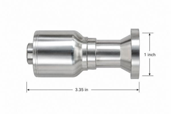
Define the port-side question
Record the flange interface required by the mating port or adapter, including the applicable standard or controlled equipment drawing. Identify nominal size only as one field. Add flange head dimensions, sealing arrangement, split or captive clamp context where relevant, fastener interface, and the functional connection datum used by the drawing.
Do not call a flange Code 61, Code 62, or another family from appearance or nominal size alone. Similar-looking heads can have different dimensions, pressure scopes, seals, clamps, or fastening requirements. The order should cite the source that establishes the interface rather than ask the supplier to infer it from a photograph.
Define the hose-side question
Record the complete hose manufacturer, hose series, construction, ID or dash size, and the fitting series approved for that hose. Identify whether the fitting body or stem and ferrule are preassembled or retained as a one-piece product and note the exact SKU or drawing revision when known.
The hose side also needs current preparation, insertion, crimp equipment, tooling, measurement, and acceptance data. Matching hose dash to flange nominal size does not prove compatibility. Port size and hose size serve different functions and may not be the same.
Keep these field groups separate in the RFQ:
- Flange interface, seal, clamp, and mating-port requirements
- Hose manufacturer, series, construction, and size
- Fitting stem, ferrule, angle, and orientation
- Crimp-process reference and installation-envelope limits
Identify the Flange Interface From Controlled Evidence
Flange identification should begin with the mating equipment and its drawing whenever possible. An old fitting can supply useful dimensions, but wear, damage, and incomplete measurement can make it an unreliable sole standard.
Name the applicable interface source
Use the current equipment drawing, port drawing, applicable standard, or approved component specification that defines the connection. Record the document identifier and revision. If the interface is proprietary or modified, say so explicitly and request a controlled detail rather than forcing it into a familiar flange label.
Confirm whether the connection uses a flanged head with separate clamps, a block or pad, a captive arrangement, or another design. The word “flange” is not a complete product category. The specification must describe the exact mating system and the parts included or excluded from the order.
Keep identity separate from pressure suitability
Correct flange identification does not establish a universal working pressure. Suitability depends on the exact flange head, clamps, fasteners, seal, mating port, hose assembly, temperature, fluid, loading, installation, and applicable documentation. The lowest-rated or least-suitable component and condition can govern the assembly.
Do not copy a pressure value or torque from a visually similar connection. Request the current approved rating and installation procedure for the complete interface and application. If that evidence is absent, the specification remains incomplete.
Capture Head Geometry, Critical Dimensions, and Seal Type
The drawing should define dimensions from functional datums so both buyer and reviewer measure the same geometry. Avoid vague fields such as “head width” without a reference view.
Build a dimensioned interface view
Depending on the design, useful fields may include flange head width and thickness, sealing-face diameter, nose or pilot geometry, relevant radii, centerline location, and clearance around the clamp area. Name each datum and indicate whether the value comes from the equipment drawing, original fitting drawing, or controlled measurement.
Photographs should show the complete fitting, flange face, side profile, hose end, and a scale, but photos do not replace dimensions. A perspective image can distort thickness, diameter, and angle. Include a sketch with labeled dimensions even when a formal CAD drawing is not available.
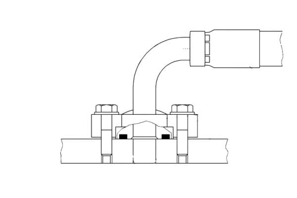
Identify how the interface seals
State whether sealing occurs through an O-ring, another specified seal, or a drawing-defined face arrangement. Record groove or seal location through controlled geometry and identify the required seal material only from approved fluid, temperature, and equipment data. Do not substitute a seal because it fits physically.
Inspect the mating face and old component for damage, but do not treat an imprint or leftover seal as conclusive evidence of the original design. If the seal type or groove geometry is unclear, request the port drawing and fitting detail before selection.
Confirm Clamp, Port, and Fastening Compatibility
The flange head works as part of an interface that may include clamps, bolts, washers, a mating pad, and an O-ring. Those surrounding parts need compatible geometry and approved installation requirements.
Describe the mating hardware context
Record the clamp style and part identity where known, the port or pad reference, fastener arrangement, and whether existing hardware is intended for reuse under the equipment procedure. Note obstacles that restrict clamp placement or bolt access. Do not assume every clamp matching the nominal flange size fits every head family.
The request should state whether clamps, seals, and fasteners are included with the fitting or supplied separately. This prevents a correct flange head from arriving without the components needed for the approved interface.
Leave torque and installation values to controlled data
Fastener grade, lubrication condition, thread condition, clamp design, port material, and manufacturer procedure can affect assembly requirements. Do not place a guessed torque in the RFQ or copy one from another flange. Cite the applicable installation instruction and revision instead.
Before disassembly or measurement, stop the equipment, isolate the hydraulic system, release pressure and stored energy, secure raised loads, and follow lockout and manufacturer procedures. Never loosen a flange connection to identify it while the circuit can contain pressure.
Complete the Hose-End and One-Piece Fitting Definition
A correct flange head attached to the wrong stem or ferrule still creates an unacceptable hose assembly. The specification must connect the port geometry to an approved hose-side system.
State size, series, and assembly basis
List hose manufacturer, complete series, construction, ID or dash, fitting series, and full fitting code when available. Add the required preparation method, such as skive or no-skive only when current approved data specify it, along with insertion reference, machine basis, tooling, crimp measurement method, and acceptance-document revision.
Do not publish or infer a universal crimp diameter, insertion depth, die, or preparation rule. Each value must apply to the exact hose, fitting, ferrule, equipment, and controlled procedure. If mixed-brand use is proposed, request explicit approval evidence for that combination.
Define angle and orientation
Identify straight, 45-degree, 90-degree, or other drawing-defined geometry. For angled ends, specify the relationship between the flange sealing face, clamp orientation, elbow plane, and hose centerline. For a two-ended hose assembly, include relative end clocking and the method used to measure it.
Terms such as “left,” “up,” or “same as old” are ambiguous without an installed reference. Use a labeled view, datum, and viewing direction. Swivel capability during installation does not automatically permit rotation during service.
Verify Envelope, Routing, and Service Clearance
An interface can be technically correct and still fail to fit the equipment. Compare the proposed fitting’s complete three-dimensional envelope with adjacent ports, guards, structures, hoses, and the tools needed for installation.
Map the rigid fitting envelope
Use drawing dimensions to locate the flange face, elbow centerline, body, ferrule, and hose tangent relative to the equipment port. Check head and clamp clearance, body projection, elbow drop or sweep, and the space required to insert and tighten hardware. A nominal angle does not define those distances.
For replacement work, compare the old and proposed outlines from the same datum. Do not force the hose, bend it below manufacturer limits, or use clamp tightening to pull a misaligned fitting into position.

Include operating and maintenance space
Installation clearance is only the static starting point. Review hose bend radius, movement, vibration, articulation, nearby hot or abrasive surfaces, and equipment motion using approved design data. Preserve access for inspection, retightening when specified, and future removal without using the hose as a handle.
If a full motion check is needed, use a safe approved method with pressure released and loads controlled. A gap observed in one machine position does not prove clearance throughout operation.
Write a Specification Line That Exposes Unknowns
A structured line reduces assumptions by making missing fields visible. Use placeholders until each field is supported; do not fill them with guessed codes or dimensions.
Example specification format
Flange-end one-piece hose fitting: Interface standard/drawing [document and revision]; nominal interface size [value]; head geometry [drawing/dimensions]; seal type and location [approved definition]; clamp/port context [part or drawing]; hose manufacturer and series [identity]; hose size [identity]; fitting series/SKU [identity]; configuration [straight/angle]; orientation datum [drawing reference]; material/finish [requirement]; envelope limits [dimensioned sketch]; assembly/crimp instruction [document and revision]; application conditions [fluid, pressure, temperature, motion, environment].
This format is a request framework, not a technical approval. Every bracketed field should trace to an equipment requirement, product drawing, compatibility record, or approved process source.
Drawing and photo request checklist
Prepare the following package before ordering:
- Port or equipment drawing with interface standard and revision
- Original fitting part number and drawing, when reliable
- Front, side, sealing-face, hose-side, and installed-orientation photographs
- Labeled datum sketch with flange head, seal, centerline, angle, and envelope dimensions
- Clamp, fastener, mating port, and included-component information
- Hose manufacturer, series, construction, size, and current crimp-data reference
- Service conditions, routing, motion envelope, and tool-access constraints
- List of unknown or conflicting fields requiring technical clarification
When a field cannot be confirmed, keep the placeholder visible and assign it to a source owner. For example, the equipment drawing owner may need to confirm the port interface, while the hose-system authority confirms the fitting series and crimp basis. Do not let a commercial description silently become an engineering decision. The response to the RFQ should repeat the proposed values, drawing revisions, inclusions, exclusions, and remaining exceptions so they can be reviewed line by line. If a proposed product differs from the requested envelope, seal arrangement, hose combination, or hardware context, require a revised drawing and technical disposition before approving the order. This closed-loop comparison prevents an incomplete request from becoming an equally incomplete purchase record.
Conclusion
A usable flange fitting specification connects a verified equipment interface to a verified hose assembly system. Identify the applicable flange standard or controlled drawing, define head geometry and sealing details from named datums, and document the clamp, port, fastener, and included-part context. Then add the exact hose series, size, fitting and ferrule design, approved crimp process, angle, orientation, and application conditions. Compare the complete envelope with routing, motion, and service access before approving a replacement. Nominal size, a photo, or a familiar flange label cannot prove interchangeability or pressure suitability. For flange-end one-piece hose fittings, the next practical step is to prepare a revision-controlled port drawing, dimensioned fitting sketch, hose data, assembly instruction, and list of unresolved fields.
Frequently Asked Questions
Is nominal flange size enough to select a hose fitting?
No, nominal size does not define the flange family, head geometry, seal, clamps, hose side, or pressure scope. Confirm the complete mating interface from a current standard or controlled drawing.
Can an old flange fitting be identified from photographs alone?
No, photographs support screening but can distort or hide critical geometry. Add controlled dimensions, functional datums, sealing details, part markings, and the mating-port drawing.
Should clamps and seals be included in the fitting specification?
Yes, the request should state clearly whether they are included or supplied separately. Their exact identity and compatibility still require approved interface data.
Does the flange size have to match the hose dash size?
No, port-interface size and hose size describe different parts of the assembly. Select each from the application and approved product data rather than assuming the labels must match.
Can torque be copied from a similar flange connection?
No, installation requirements depend on the exact interface, hardware, condition, and manufacturer procedure. Cite the current controlled installation instruction instead of using a borrowed value.