
Flat thread crests on hydraulic fittings are not automatically defective. A controlled thread form normally includes some crest truncation, but a flat-looking area can also result from incomplete machining, local crushing, torn metal, coating buildup, or damage after manufacture. The practical question is not whether the crest looks sharp or flat; it is whether the complete thread and connection meet the current drawing and applicable thread requirements. Inspection teams should separate thread identity, dimensional conformity, sealing-interface condition, and possible root cause before accepting or rejecting a lot.
Start With the Thread Requirement, Not the Photograph
A photograph can document an observation, but it cannot by itself establish hydraulic thread acceptance. Lighting, viewing angle, coating reflection, focus, and magnification change the apparent width of a crest, while a two-dimensional image hides pitch diameter, lead, taper, and flank condition.
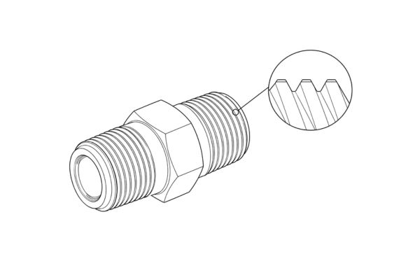
Intended truncation has a controlled context
Thread crests and roots are not simply theoretical sharp points on a finished component. Their permitted form depends on the identified thread designation, the applicable standard or product drawing, manufacturing allowances, coating condition, and whether the thread is internal or external. A visibly flat crest may therefore be consistent with the specified profile, but only the governing requirement can establish that conclusion.
The connection must first be identified correctly. Record the nominal designation, pitch or threads per inch, straight or tapered form, class or tolerance designation when applicable, male or female end, and drawing revision. Do not borrow crest expectations from a similar-looking JIC, ORB, BSP, NPT, metric, or another connection; shared diameter or successful engagement does not make their thread requirements identical.
A flat appearance can describe several different conditions
Use neutral language before the evidence is complete. “Continuous flat crest around several turns” is an observation. “Thread made from an undersized blank” is a root-cause hypothesis that requires material and production records. Keeping those statements separate prevents a visual finding from becoming an unsupported manufacturing conclusion.
Useful initial classifications include:
- continuous, uniform crest truncation around the circumference;
- a localized dent, rolled edge, or crushed area;
- incomplete form limited to certain turns or sectors;
- torn, smeared, folded, or raised metal;
- coating buildup, embedded debris, or corrosion product; and
- contact damage associated with handling or previous assembly.
Separate Profile Shape From Functional Damage
Intended truncation should be consistent with the specified thread profile; damage interrupts or displaces that profile. Inspectors should look beyond crest width and examine continuity, symmetry, flanks, roots, starts, runouts, and the relationship between the suspect area and mating contact.
Localized crushing and torn metal leave different evidence
A crushed crest may show displaced material, a polished contact mark, an abrupt change across adjacent turns, or asymmetry around the circumference. Torn metal may produce a lip, feather, rough surface, or loose projection. Either condition can interfere with engagement, damage a mating thread, or create debris even if much of the thread appears normal.
Incomplete form is different again. A crest can remain broad because the cutting or forming operation did not create the required depth or full profile. That possibility must be tested against pitch diameter, major diameter, flank form, and production evidence. It cannot be proved merely by noting that the crest is wider than an inspector expected.
The sealing interface remains a separate acceptance item
Many hydraulic connections seal at a flare, cone, flat face, O-ring, bonded seal, or another designed surface rather than at the visible external crest. A conforming thread does not approve a damaged seat, and an acceptable seat does not excuse a nonconforming thread. For tapered thread-sealed connections, the thread also participates in sealing, but identity, taper, engagement, and approved sealant practice still require separate confirmation.
Never force a nut or gauge over a suspect area to see whether it “clears” the crest. That can alter the evidence, damage both parts, and create a misleading pass. Installed components must be isolated, depressurized, and relieved of stored energy under the equipment procedure before removal or inspection.
Use Each Inspection Method for the Question It Can Answer
No single tool establishes every characteristic of a hydraulic fitting thread. A sound decision combines observations and measurements that are traceable to the requirement being evaluated.
Screening tools have firm boundaries
The following table keeps common methods in their proper roles.
| Method | What it can establish | What it cannot establish alone |
| Photograph or microscope image | Location, continuity, surface condition, visible damage | Full three-dimensional profile, pitch diameter, cause |
| Caliper or micrometer | A defined outside dimension when measured correctly | Pitch diameter, lead, flank angle, complete profile |
| Mating production part | Assembly behavior for that particular pair | Conformity of either part or the complete thread system |
| Correct thread gauge | The characteristics represented by that gauge and procedure | Sealing-face condition, material, all profile details, root cause |
| Optical profile or comparator method | Documented crest, flank, root, and form geometry when validated | Production history or service suitability beyond the measured profile |
A mating nut that starts and tightens is useful evidence of assembly behavior, not a substitute for thread inspection. Oversize and undersize conditions can sometimes pair, damaged threads can cut their own path, and the nut may itself be worn or nonconforming. Protect reference masters from investigative use that could damage them.
Measurement location and preparation matter
Clean the thread only by the approved method and record the coating or finish condition. Identify which turns and circumferential positions were examined, how the part was supported, and which datum or alignment method was used. If an optical system is used, confirm calibration, orientation, edge-detection settings, magnification, and whether the coating boundary or base-metal boundary defines the reported edge.
Major diameter, pitch diameter, pitch, lead, taper, flank angle, crest form, and root form answer different questions. The drawing and applicable thread specification determine which are controlled and how. Avoid inventing a universal acceptable crest width or assuming that a major-diameter result describes the entire profile.
Determine What Actually Governs Acceptance
Acceptance should trace to a released drawing, referenced standard, approved inspection plan, and any product-specific requirements. If these sources conflict or omit the disputed feature, engineering must resolve the requirement before batch screening begins.
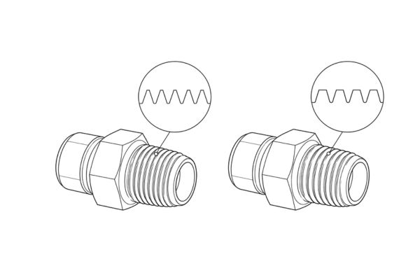
Build a requirement hierarchy
Confirm the complete part number and revision first. Then identify the referenced thread designation and inspection notes, including coating allowance, gauge practice, edge requirements, and any profile callout. Record whether the drawing dimension applies before or after finishing and whether a general tolerance note legitimately applies to that characteristic.
An inspector should not create a new acceptance rule from one approved sample. A reference sample can help communicate appearance, but it may not represent tolerance limits and may have wear or an unknown revision. Likewise, a supplier certificate does not replace inspection of a reported nonconformity unless the certificate covers the exact characteristic, lot, method, and requirement at issue.
Resolve missing criteria before sorting a batch
When crest geometry is not explicitly dimensioned, do not assume that “sharp is correct” or that any flat is allowed. Ask the responsible engineering authority to state the applicable profile requirement and an inspection method capable of evaluating it. That agreement should identify the characteristic, equipment, preparation, measurement locations, result format, acceptance boundary, and treatment of measurement uncertainty.
This step protects both parties. Without a common method, one side may measure reflected coating at the crest while another measures the base profile; both can produce numbers that are internally repeatable yet not comparable. A controlled method turns a visual dispute into a reproducible engineering decision.
Interpret Repeated Crest Findings Without Guessing the Cause
Repeated findings at the same feature justify containment and a production-record review, but repetition does not prove a particular cause. The pattern narrows the investigation only when part identity and evidence are reliable.
Compare like with like
Group findings by complete part number, drawing revision, lot, machine or process route when known, material condition, finish, and inspection method. Map the affected turns and circumferential sectors. Compare unused retained samples with handled, gauged, assembled, or returned parts so post-production damage is not mixed with original condition.
Look for whether the condition is:
- common to all inspected pieces or isolated;
- continuous around the thread or limited to one sector;
- present before coating, visible only after coating, or associated with debris;
- linked to one tool, setup, blank source, handling step, or packaging condition in traceable records; and
- accompanied by changes in major diameter, pitch diameter, form, gauge result, or mating behavior.
Manufacturing explanations remain hypotheses until supported
An insufficient machining blank diameter can contribute to incomplete external thread form, but that explanation requires blank specifications, measured incoming or in-process material, tool and setup records, and profile evidence. Tool wear, incorrect setup, forming variation, coating, handling damage, or an incorrect drawing interpretation may produce different patterns. Do not select a cause because it sounds plausible or because several parts share a flat crest.
Reviewing records should also test whether the inspection system could have missed the characteristic. A creation cause and an escape cause are not necessarily the same. Correcting a machining condition does not improve release control if the final inspection method still cannot see or measure the disputed profile.
Contain the Lot With Agreed Inspection Criteria
Containment prevents suspect and accepted material from mixing while the requirement is resolved. It is a temporary risk-control action, not proof that every part in the lot is defective.
Preserve traceability before screening
Segregate affected and potentially related stock according to the quality procedure. Preserve labels, packaging, lot records, photographs, measuring results, and the original condition of representative samples. Do not chase threads, file crests, force a gauge, or assemble parts to remove raised material before evidence is documented.
The screening instruction should name the exact feature and approved method. It should also define which lots are in scope, who is qualified to inspect, how inaccessible areas are recorded, how borderline results are handled, and how accepted and rejected parts remain traceable. “Check for flat threads” is too subjective for reliable sorting.
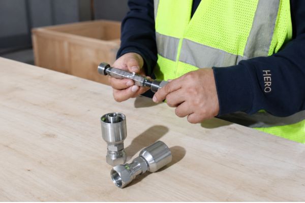
Sample results have limited reach
One conforming piece cannot release an entire shipment unless the approved sampling or screening plan supports that decision. Conversely, one rejected piece does not prove every part has the same condition. Use the applicable quality plan and risk assessment to decide whether targeted sampling, expanded sampling, or full screening is required.
Measurement uncertainty matters near a limit. Repeated readings, suitable resolution, controlled fixturing, and agreement between methods may be necessary before disposition. Report the uncertainty instead of converting an ambiguous result into a confident pass or fail.
Keep Rework, Replacement, and Verification Controlled
Thread repair changes a functional, load-carrying interface and must never become an informal shop correction. Chasing, filing, rolling, or abrasive cleanup can alter flank contact, coating, geometry, contamination level, and fatigue-sensitive surfaces.
Rework needs explicit authorization
An approved rework instruction should identify eligible conditions, tools, material-removal limits, cleaning, coating restoration, personnel qualification, and reinspection. Parts with torn metal, cracks, severe crushing, uncertain identity, or geometry that cannot be restored within the controlled requirement may require replacement rather than rework. A gauge pass after uncontrolled thread chasing does not validate the original part or the repair.
Replacement also requires complete connection verification. Confirm the thread and sealing interface, orientation, material and finish, application conditions, and—where the fitting terminates a hose—the hose manufacturer, hose series, size, fitting series, crimp equipment, dies, and current crimp specification. Visual similarity and dash size are not compatibility evidence.
Verify the correction at the characteristic that failed
After an approved process correction, repeat the profile or dimensional method that found the problem and verify related characteristics that the correction could affect. Then review subsequent traceable lots to determine whether the condition recurs. A short run without a finding supports follow-up, but it does not prove permanent prevention without an adequate control plan.
Prepare this thread-profile evidence checklist for disposition:
- complete part number, lot, material, coating, and drawing revision;
- thread designation, size, pitch, straight or tapered form, and connection type;
- mapped crest location plus overview and close-up images;
- major- and pitch-diameter results and other required profile data;
- gauge identity, calibration status, method, and result;
- profile-inspection setup, measurement locations, and uncertainty;
- sealing-face condition and separate connection checks; and
- containment scope, approved disposition, rework record, and reinspection result.
Conclusion
Flat thread crests on hydraulic fittings require evidence, not a visual shortcut. Intentional truncation, incomplete form, localized crushing, torn metal, and coating buildup can look similar in a photograph but demand different decisions. Start with the current drawing and correct thread designation, then use photographs, dimensional measurements, the appropriate gauges, and profile inspection only for the characteristics each method can establish. Keep thread conformity separate from sealing-interface acceptance and from root-cause verification. Repeated findings justify traceable containment and a production-record review, not an automatic claim about blank size or tooling. Before release, replacement, or approved rework, document the lot, inspected locations, measurement method, uncertainty, acceptance criteria, and the verification results tied to the actual hydraulic fitting thread profile.
Frequently Asked Questions
Is every flat external thread crest a defect?
No, a flat crest may be intentional truncation within the specified profile. Acceptance depends on the actual thread designation, drawing, finish condition, and required dimensional or profile checks.
Can a ring gauge prove that the crest shape is acceptable?
Not by itself. A correct ring gauge evaluates the characteristics represented by its design and procedure, but it does not independently approve every crest, root, sealing surface, coating condition, or cause.
Does a mating nut prove that a hydraulic fitting thread conforms?
No, it proves only that those two particular parts can engage under the observed conditions. Either part may be worn or dimensionally offset, and successful engagement does not verify the complete profile.
Can flat crests prove that the machining blank was too small?
No, insufficient blank diameter is only one possible hypothesis. Confirm it with controlled blank dimensions, production records, tool and setup evidence, and measured thread-profile results.
May a suspect thread be chased and then accepted?
Only when an approved engineering rework instruction permits it and defines subsequent cleaning, finish restoration, and reinspection. Informal thread chasing can remove evidence and create new dimensional or contamination risks.