
When a hydraulic tube won’t fit into a hydraulic fitting, the nominal labels may match while the actual mating geometry does not. The obstruction may be at the bore entrance, along the tube end, or deeper at a shoulder or internal restriction. It can result from tube outside diameter, ovality, burrs, bore size, finish, damage, or two specifications that never established a workable fit.
Define the Receiving Feature Before Measuring It
Not every opening in a hydraulic fitting is intended to accept a rigid tube as a free-sliding clearance fit. The first task is to identify the connection design, the tube function, and the drawing feature into which the tube is supposed to enter.
A bore name does not define its function
A flow passage, seal bore, brazing socket, cutting-ring interface, pilot, counterbore, and assembly clearance feature can have very different requirements. Some designs intentionally create interference or form a seal during an approved assembly operation; others require initial free entry. Do not apply a “tube must slide in” rule until the current product drawing and assembly instructions show that this is the intended condition.
Confirm the complete part numbers, drawing revisions, tube specification, connection standard, material and finish condition, and the exact assembly step at which the problem occurs. Keep hose stems and crimp sockets outside this investigation. A hose bore and a rigid-tube receiving feature are not interchangeable concepts even when both are described casually as a fitting bore.
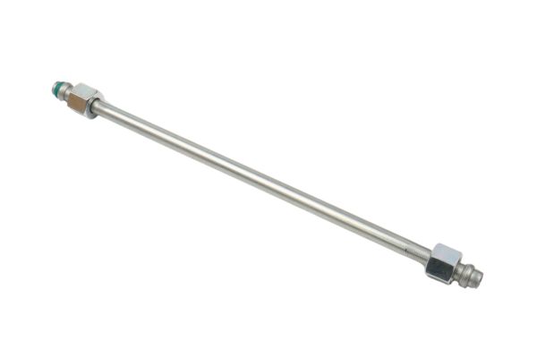
Record the intended engagement
The drawing should identify the entrance diameter, any chamfer or lead-in, the controlled internal diameter, insertion depth, shoulder location, and the surfaces that seal or locate the tube. It should also state whether dimensions apply before or after coating, plating, forming, heat treatment, or another finishing operation. If these details are absent, engineering must define the mating requirement before production screening begins.
Prepare the intended sequence as a simple statement: which tube end enters which feature, how far it should travel before another component acts, and whether force or tooling is permitted. Never use a nut to pull the tube into place unless the specific connection procedure requires that action. Improvised force can hide interference, damage the tube, or load a sealing surface incorrectly.
Entry Failure and Partway Stoppage Point to Different Zones
Where the tube stops is valuable evidence. Immediate refusal usually directs attention to the tube end and bore entrance, while free initial travel followed by a stop shifts the review to deeper geometry and alignment.
When the tube will not start
Inspect the tube cut end for flare, rollover, burrs, dents, out-of-round form, coating buildup, and damage from clamping or cutting. Measure outside diameter at several angular positions and at more than one distance from the end. One caliper reading across the smallest axis can miss ovality and falsely suggest that the tube should enter.
Inspect the fitting entrance for a damaged or missing chamfer, raised edge, plating accumulation, embedded particle, deformation, or an undersize mouth. Use suitable lighting and non-damaging magnification. Do not sand the tube, scrape the bore, or use insertion itself to break off a burr; those actions change the evidence and may introduce contamination.
When the tube stops after entering
A partway stop can occur at an internal shoulder, a smaller downstream diameter, a local high spot, an intersecting passage, coating, debris, taper, or misalignment between stepped features. Mark the insertion position without scratching the component and compare the observed depth with the controlled drawing. A depth mismatch helps locate the obstruction but does not identify its cause.
Check whether the tube remains coaxial with the receiving feature. Side load, bent tube, fixture error, or an angled cut can make an otherwise adequate bore bind. Rotate-and-force trials are unsuitable because they can burnish the contact point and make later inspection harder to interpret.
Inspect the Tube Before Blaming the Fitting Bore
The tube is one half of the fit and needs its own controlled evidence. A nominal outside diameter does not describe the actual maximum envelope presented to the fitting.
Diameter, ovality, and end condition work together
Measure outside diameter with equipment and technique appropriate to the tolerance. Take readings across multiple angular orientations, especially near the cut end, and compare them with readings farther back on an undamaged section. Record the maximum observed diameter rather than averaging away a local high condition.
Roundness is not established by one minimum and one maximum reading unless the approved method defines it that way. Form error may vary continuously around the circumference, and a locally flattened section can create high points elsewhere. Tube specification, forming history, straightening, cutting, transport, and clamping records may be relevant, but none should be named as the cause without evidence.
Preserve the original cut end
Document burr direction, rollover, chamfer, squareness, finish, and any tool marks before deburring or cleaning. If the assembly drawing calls for an end preparation, verify that preparation against the controlled requirement. A tube may have an acceptable body diameter yet fail at a flared, mushroomed, or angled end.
Useful tube evidence includes:
- complete tube specification, material, finish, heat or lot identity;
- measured outside diameter by location and angular position;
- approved roundness or ovality result;
- cut-end photograph and end-preparation record;
- straightness or alignment evidence when relevant; and
- the measured depth and orientation at which insertion stops.
Measure the Bore at the Locations That Control Assembly
A bore measurement is meaningful only when its location, tool, contact geometry, and uncertainty match the feature under investigation. A value at the entrance cannot clear a restriction deeper in the fitting.

Map the entry, controlled length, and shoulder
Use the drawing to divide the receiving feature into zones: entry chamfer, initial diameter, full engagement length, transition, shoulder, and downstream passage. Measure at the locations specified by the inspection plan and add targeted locations around the observed stop when engineering authorizes them. Record depth from a defined datum so another inspector can reproduce the result.
A two-point bore gauge, air gauge, plug gauge, optical system, coordinate measurement method, or another tool may be appropriate depending on feature size, access, tolerance, and required form information. Each method has limits. A go plug can test passage through its represented size and length, but it does not provide the full bore map or automatically distinguish taper, lobing, a burr, and misalignment.
Account for access and measurement uncertainty
The entrance chamfer can tilt a tool or produce an unrepresentative reading. Short contact points may bridge a local groove, while long gauges may stop at a shoulder. Surface finish, temperature, cleanliness, operator alignment, calibration, and tool resolution can all influence results near a limit.
Use repeated measurements and suitable fixturing when the decision is close. State uncertainty and inaccessible zones instead of reporting a false level of precision. If the tool cannot reach the suspected depth, use another approved method or escalate the limitation; do not declare the bore conforming because its easiest location passed.
Read Tolerances as Limits, Not as Plus Signs
Unilateral and bilateral tolerances describe permitted limits in different notation. The practical fit decision always depends on the smallest permitted receiving feature and the largest permitted mating tube under the same defined condition.
Find the actual lower and upper limits
For a bore shown with a positive unilateral tolerance, the stated nominal value is commonly the lower limit and the tolerance extends upward, but the drawing convention and notes must be confirmed. For a tube with a negative unilateral tolerance, the nominal may be the upper limit. Bilateral tolerances extend in both directions, whether symmetrically or asymmetrically.
Do not compare only nominal values or add the plus tolerance to the bore and call the result “the required size.” Determine the explicit lower and upper limits for both features, including any finish allowance. Then calculate whether the worst-case combination provides the clearance, transition, or interference the design actually requires.
A symbolic worst-case check avoids invented dimensions
Let the permitted bore range be from Bmin to Bmax and the permitted tube outside-diameter range be from Tmin to Tmax. If the design requires positive clearance before the next assembly step, the controlling comparison is Bmin minus Tmax. Engineering must define the required result, including allowances for form, alignment, finish, temperature, and measurement uncertainty.
A favorable nominal comparison does not prove the worst-case fit. Equally, an unfavorable worst-case calculation does not prove either delivered part is out of tolerance. It may reveal that two individually conforming specifications do not guarantee the intended assembly, which is a design-interface problem rather than a simple supplier rejection.
Separate Part Nonconformity From Specification Incompatibility
The same assembly failure can arise from an out-of-tolerance tube, an out-of-tolerance bore, or two conforming parts whose specifications do not establish a functional fit. The disposition should identify which situation the evidence supports.
Use a measurement-and-decision table
| Evidence pattern | Supported conclusion | Next action |
| Tube exceeds its permitted maximum | Tube nonconformity is established for the measured characteristic | Contain traceable tube material and follow approved disposition |
| Bore is below its permitted minimum | Fitting nonconformity is established for the measured characteristic | Contain traceable fittings and review the controlled process |
| Both parts conform, but worst cases overlap improperly | Interface specification may be inadequate | Engineering review of mating requirements and tolerances |
| Dimensions pass, but a local burr or ovality causes contact | Local form or edge condition needs separate evaluation | Apply the feature-specific inspection and disposition |
| One sample assembles but others do not | Variation or mixed identity remains unresolved | Preserve lots and expand approved, traceable inspection |
One successful insertion is not authorization to accept an undersize bore. The successful pair may sit at favorable ends of their tolerance ranges, or the insertion may have changed a soft edge. Likewise, one failure does not establish that every fitting in the lot is too small.
Investigate specifications and production separately
Production records can show whether a lot, tool, setup, finishing operation, or tube process changed. Drawing history can show whether the mating parts were designed from the same interface assumptions. Keep these reviews parallel until evidence connects them. An assembly symptom alone does not establish responsibility.
If separate organizations control the tube and fitting drawings, create one interface record that identifies shared datums, measurement conditions, required fit, worst-case analysis, and verification method. This prevents both sides from meeting isolated drawings while the assembly continues to fail.
Control Screening, Rework, and Reinspection
Contain suspect material before sorting so accepted and unresolved parts do not mix. Preserve unused samples, labels, packaging, lot identities, and original measurements before any correction.
Screen the feature that governs the fit
An approved screening plan should define the tube and fitting population, measurement locations, equipment, calibration, cleanliness, qualification, acceptance limits, uncertainty treatment, and traceability of results. A plug check at the entrance cannot clear a deeper restriction, and a tube try-in can damage the feature or falsely pass only one favorable pairing.
Sampling scope should follow the quality plan and risk, not a convenient number invented for the investigation. If the issue affects a pressure-containing or sealing interface, obtain the responsible engineering disposition before release. Do not improvise drilling, reaming, sanding, tube reduction, or forced insertion.
Rework must restore all affected requirements
Approved rework must control material removal, geometry, surface finish, cleanliness, coating, and any sealing or structural feature near the bore. Reinspect the corrected dimension at all required depths and verify associated features the rework could change. Clean the part through the approved process and document the result before assembly.
For the final mating-interface package, prepare:
- complete fitting and tube part numbers, revisions, lots, and material conditions;
- a drawing section showing entry, bore, shoulder, insertion depth, and datums;
- tube OD and form results by location and orientation;
- bore results by depth and angular position, with the method and uncertainty;
- photographs of both ends and any burr, damage, coating, or restriction;
- the design’s required fit and worst-case limit comparison; and
- containment, approved disposition, rework, cleaning, and reinspection records.
Conclusion
When a tube will not fit into a hydraulic fitting, begin by defining the receiving feature and intended assembly rather than forcing the parts together. The stop location helps separate entry problems from deeper restrictions, but both tube and fitting require controlled measurements. Check tube outside diameter, ovality, cut-end condition, bore size by depth, chamfers, shoulders, alignment, finish, and measurement uncertainty. Read unilateral and bilateral tolerances as actual upper and lower limits, then compare the smallest allowed bore with the largest allowed tube under the intended fit requirement. The evidence may identify a nonconforming part or reveal two individually conforming but incompatible specifications. Before release or rework, document the interface, contain traceable material, obtain engineering disposition, and reinspect every affected characteristic.
Frequently Asked Questions
Does matching nominal tube size prove that the tube should fit?
No, nominal descriptions do not establish the actual limits or intended fit. Compare the current tube and fitting drawings, finish conditions, maximum tube envelope, and minimum receiving feature.
Can I use a nut to pull the rigid tube into the fitting?
Only if the connection’s approved assembly procedure explicitly requires that action. Otherwise, pulling the tube in can hide interference, damage components, and load the sealing interface incorrectly.
Is a plug gauge enough to approve the complete bore?
Not always. It evaluates the size and length represented by that gauge but may not reveal every local high spot, lobing condition, shoulder position, alignment error, or deeper restriction.
What if the tube fits one fitting but not another from the same lot?
Treat that as evidence of variation, mixed identity, or a marginal interface. Preserve traceability and use an approved measurement plan rather than accepting the lot from the successful pairing.
May an undersize bore be reamed to make the tube fit?
Only under an approved engineering rework procedure. Reaming can affect wall thickness, finish, coating, cleanliness, alignment, sealing geometry, and pressure-containing integrity, all of which may require reinspection.