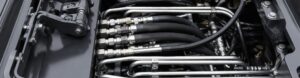
Hydraulic hose assemblies leak after installation primarily due to improper component matching, assembly errors, or incorrect routing configurations. Imagine completing a high-stakes equipment overhaul only to find fluid pooling on the shop floor during the first test run. This unexpected failure wastes expensive hydraulic fluid and risks catastrophic machine downtime that your production schedule cannot afford. By understanding the root causes and applying precision installation techniques, you can ensure that your hydraulic hose assemblies leak no more, securing your system’s integrity from day one.
Why Do Hydraulic Hose Assemblies Leak After Setup?
Post-setup leaks are usually the result of using mismatched components or failing to clean the hose before final assembly. It is a common mistake to assume all “standard” fittings are interchangeable, but slight dimensional variances can prevent a perfect seal. When hydraulic hose assemblies leak immediately after installation, you must first verify that the hose, fittings, and ferrules are from a compatible system.
Contamination trapped during the cutting process can also compromise the internal seal. If metallic shards or dust remain inside the tube, they can migrate to the fitting interface and create microscopic leak paths.
Component Compatibility Check
Selecting parts from different manufacturers often leads to tolerance gaps that pressure will eventually exploit. You should always use a matched system where the hose and fittings are designed to work together under specific compression specs.
- Verify dash sizes for both hose and fittings.
- Ensure thread types (NPT, JIC, ORFS) match the port exactly.
- Check that the pressure rating of every component meets system requirements.
Pre-Installation Cleaning Protocol
Even a brand-new hose can contain manufacturing debris that ruins a seal. Using high-pressure air or specialized projectiles to clean the hose bore ensures that no particles interfere with the metal-to-metal or O-ring contact points.
| Setup Factor | Risk Level | Primary Consequence |
| Mismatched Brands | High | Incomplete Seal Compression |
| Internal Debris | Medium | Interface Scratches |
| Incorrect Dash Size | Critical | Blow-off Failure |
Where Do Hydraulic Hose Leak Most?
Leakage occurs most frequently at the interface between the fitting and the hose or at the threaded connection to the port. These areas represent the highest points of mechanical stress and the transition between different material types. While the hose body itself is durable, hydraulic hose assemblies leak most where the flexibility of the rubber meets the rigidity of the steel fitting.
Stress concentrations are often highest at the end of the ferrule. If the hose is bent too sharply near the fitting, the internal wire reinforcement can pull away from the seal.
Critical Connection Points
The junction where the fitting enters the hose is the most vulnerable spot in any assembly. This area must withstand both the internal fluid pressure and the external mechanical forces of machine movement.
- The crimp zone where the ferrule grips the hose.
- The seating surface of the flare or O-ring.
- The thread engagement area at the manifold.
The Bending Stress Zone
Bending the hose too close to the fitting creates an uneven load on the internal tube. This stress often leads to “weeping” leaks that start small but rapidly accelerate as the internal material fatigues.
| Leak Location | Common Cause | Detection Method |
| Crimp Tail | Under-crimping | Visual “Weeping” |
| Fitting Seat | Damaged O-ring | Drip at Nut |
| Hose Body | Abrasion | External Wetting |
How Can Routing Make Hydraulic Hose Assemblies Leak?
Improper routing causes leaks by subjecting the hose to excessive tension, twisting, or sharp bends that exceed the minimum bend radius. When a hose is pulled too tight, it shrinks in length under pressure, which can pull the hose straight out of the fitting. Correct routing ensures that hydraulic hose assemblies leak less by allowing the hose to move naturally with the machine’s cycle.
Twisting a hose during installation is another major routing error. A twisted hose can experience a reduction in life of up to 90% because the internal reinforcement layers are stressed unevenly.
Bend Radius Management
Every hose has a specified minimum bend radius that must be respected to maintain internal integrity. Exceeding this limit causes the wire reinforcement to gap, which weakens the support for the inner tube.
- Use 90-degree or 45-degree elbows to avoid tight loops.
- Ensure the hose exits the fitting straight for at least twice its diameter.
- Consult manufacturer charts for specific radius limits.
Avoiding Hose Tension
Hoses naturally change length when pressurized, typically shrinking by 2% to 4%. If you do not leave enough “slack” or “live length” in the routing, the hose will tug on the fittings and cause a leak at the crimp.
| Routing Error | Physical Impact | Prevention |
| Over-Tension | Fitting Pull-out | Add 5% extra length |
| Twisting | Wire Fatigue | Use lay-line as guide |
| Tight Bends | Tube Kinking | Use elbow adapters |
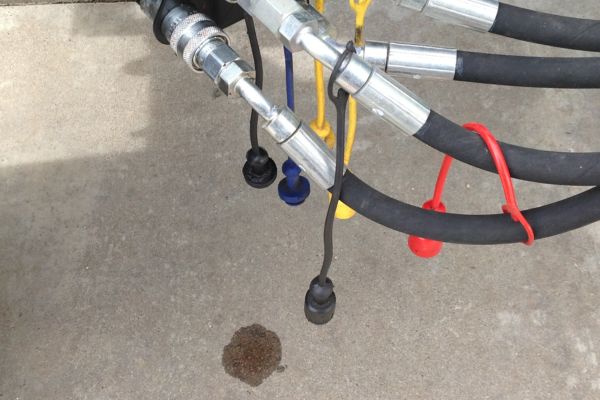
Why Do Crimped Hydraulic Hose Assemblies Leak?
Crimping leaks occur when the final diameter of the ferrule is either too large to provide a seal or so small that it crushes the internal tube. Precision is vital because even a fraction of a millimeter can be the difference between a secure fit and a failure. If your crimped hydraulic hose assemblies leak, the most likely culprit is an incorrectly calibrated crimper or the use of the wrong die set.
The “bite” of the ferrule into the wire reinforcement must be consistent across the entire circumference. Uneven crimps create leak paths that fluid will eventually find under high pressure.
Crimp Diameter Precision
Every hose and fitting combination has a specific “crimp spec” provided by the manufacturer. You must measure the finished crimp with a calibrated micrometer to ensure it falls within the allowable tolerance.
- Calibrate crimping machines daily or per shift.
- Use only the recommended die set for the specific fitting.
- Record finished diameters for quality control.
Stem and Ferrule Alignment
If the hose is not fully “bottomed out” in the fitting before crimping, the seal will be incomplete. The ferrule must grip the wire reinforcement at the correct longitudinal position to ensure a permanent, leak-proof bond.
| Crimping Issue | Visual Sign | Root Cause |
| Over-crimp | Cracks in Ferrule | Too much pressure |
| Under-crimp | Hose Slippage | Wrong die size |
| Misalignment | Crooked Ferrule | Poor insertion |
Can High Pressure Make Hydraulic Hose Assemblies Leak?
Operating a system above the rated working pressure of the hose will inevitably lead to a breach of the seal. Pressure spikes or “surges” can momentarily exceed the hose’s design limits, causing the wire reinforcement to stretch and the hydraulic hose assemblies leak at the weakest point. You must ensure that the hose’s working pressure rating exceeds the maximum possible pressure the system can generate, including surges.
Pressure ratings are not suggestions; they are calculated limits based on the tensile strength of the reinforcement layers. Using a low-pressure hose in a high-pressure circuit is a guaranteed recipe for immediate failure.
Managing Pressure Surges
Hydraulic systems often experience rapid pressure fluctuations when valves open or close suddenly. These spikes can be significantly higher than the steady-state operating pressure and can weaken the hose-to-fitting bond over time.
- Install accumulators to absorb pressure shocks.
- Use hoses with higher spiral-wire counts for high-surge tasks.
- Verify relief valve settings to cap maximum pressure.
Safety Factor Understanding
Most hydraulic hoses have a 4:1 safety factor, meaning the burst pressure is four times the working pressure. However, you should never operate in this “buffer zone,” as it rapidly degrades the hose materials and leads to pinhole leaks.
| Pressure Level | Hose Reaction | Long-term Effect |
| Rated Pressure | Normal Expansion | Expected Service Life |
| Surge Pressure | Stress on Wires | Reinforcement Fatigue |
| Over-Pressure | Tube Rupture | Immediate Catastrophic Leak |
Do Heat Spikes Make Hydraulic Hose Assemblies Leak?
Extreme heat causes the rubber inner tube to harden and crack, a process known as “thermal degradation.” Once the rubber loses its elasticity, it can no longer maintain a tight seal against the fitting, and hydraulic hose assemblies leak as a result. If you notice the hose looks charred or “cracks” when bent, it has likely been exposed to temperatures beyond its rated capacity.
High ambient temperatures from nearby engines or furnaces can be just as damaging as high fluid temperatures. External heat can bake the outer cover, allowing moisture to reach and corrode the wire reinforcement.
Fluid Temperature Control
Hydraulic oil that runs too hot thins out, which makes it easier for the fluid to weep through microscopic gaps in the seals. Maintaining optimal oil temperature is critical for both the pump’s health and the hose’s integrity.
- Clean heat exchangers and oil coolers regularly.
- Check for internal valve leaks that generate friction heat.
- Use high-temperature rated hoses (e.g., EPDM or PTFE) if needed.
External Heat Shielding
In environments like steel mills or engine compartments, hoses often require extra protection from radiant heat. Firesleeves or heat shields can reflect external thermal energy and keep the hose within its operating window.
| Temperature Source | Symptom | Solution |
| Internal Fluid | Hardened Inner Tube | Increase Cooling |
| Radiant Heat | Cracked Outer Cover | Use Fire Sleeves |
| Environmental | Premature Aging | Reroute Hose |
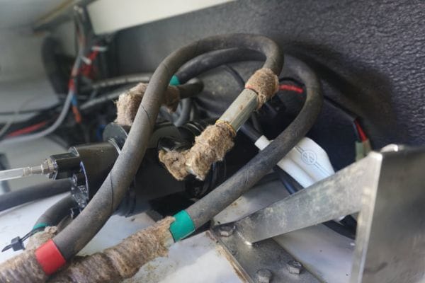
Why Do Hydraulic Hose Assemblies Leak From Vibration?
Constant vibration can cause fittings to loosen over time or lead to work-hardening of the metal components. In high-vibration applications, hydraulic hose assemblies leak because the repetitive motion creates mechanical fatigue at the fitting interface. You must use proper clamping and support to isolate the hose from the vibration generated by pumps and engines.
Vibration can also cause “fretting,” where the hose rubs against a bracket or another hose. This abrasive action thins the outer cover and eventually exposes the wire reinforcement to the elements.
Implementing Proper Clamping
Clamps should be used to secure the hose and prevent it from whipping or vibrating excessively. However, the clamps must be the correct size; if they are too tight, they can create a stress point that leads to a leak.
- Space clamps according to manufacturer recommendations.
- Use rubber-cushioned clamps to absorb mechanical shock.
- Ensure clamps do not compress the hose diameter.
Damping System Harmonics
Sometimes the vibration is caused by hydraulic “noise” or harmonics within the fluid itself. Using a longer hose or a specific hose type with better damping characteristics can help neutralize these destructive pulses.
| Vibration Type | Resulting Damage | Mitigation Strategy |
| High Frequency | Fitting Loosening | Use Lock Wire/Washers |
| Low Frequency | Hose Whipping | Rigid Clamping |
| Constant Rubbing | Cover Abrasion | Spiral Guards |
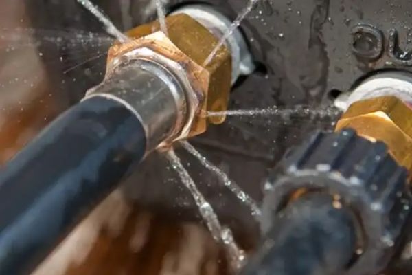
Why Do Hydraulic Hose Assemblies Leak At Fittings?
Fitting leaks are most often caused by improper torque—either too loose to seal or so tight that the threads are stripped or the flare is crushed. Many technicians mistakenly believe that “tighter is better,” but over-torqueing is a leading cause of hydraulic hose assemblies leak issues in B2B environments. You should always use the “Flats From Finger Tight” (FFFT) method or a calibrated torque wrench to achieve the perfect seal.
Damaged threads or contaminated seating surfaces also contribute significantly to fitting failures. Even a single burr on a JIC flare can prevent a metal-to-metal seal from forming.
Torque and Tightening Standards
Different fitting styles require different tightening techniques. For example, O-ring Face Seal (ORFS) fittings rely on the compression of a rubber seal, while JIC fittings rely on metal-to-metal contact.
- Always clean threads and seating surfaces before assembly.
- Lubricate threads with system oil to ensure accurate torque.
- Follow the FFFT chart for the specific fitting size.
Inspecting Fitting Seats
Before connecting any fitting, perform a visual inspection of the seating area. Look for scratches, nicks, or signs of corrosion that could compromise the seal once pressure is applied.
| Fluid Factor | Effect on Hose | Prevention |
| Incompatibility | Chemical Breakdown | Check STAMPed info |
| Particulates | Internal Erosion | High-quality Filtration |
| Water Content | Wire Corrosion | Regular Fluid Analysis |
Can Inspections Stop Hydraulic Hose Assemblies Leak?
Regular inspections identify early signs of wear, such as cover abrasion or weeping at the fittings, before they turn into major leaks. While you cannot stop every leak, a proactive maintenance program ensures that hydraulic hose assemblies leak are caught while they are still manageable “drips” rather than “bursts.” You should establish a routine schedule to check all high-pressure lines for signs of fatigue or environmental damage.
Effective inspection involves more than just a quick look. It requires a systematic approach to check for routing changes, loose clamps, and signs of overheating.
Developing an Inspection Checklist
A standardized checklist ensures that no component is overlooked during a maintenance round. This documentation also helps track the service life of specific hoses to predict when they might need replacement.
- Check for “weeping” around crimped ferrules.
- Inspect the outer cover for blisters or wire exposure.
- Verify that all clamps are secure and in the correct position.
Utilizing Modern Detection Tools
In complex systems, small leaks can be hard to find. Using ultrasonic leak detectors or UV-dye additives can help locate the exact source of a leak without requiring a full system teardown.
| Fitting Type | Sealing Method | Common Failure |
| JIC 37° Flare | Metal-to-Metal | Cracked Flare Nut |
| ORFS | O-ring | Pinched/Torn O-ring |
| NPT Pipe | Thread Interference | Galling/Stripped Threads |
Conclusion
Preventing leaks in your hydraulic system requires a dedicated focus on component compatibility, precision assembly, and thoughtful routing. By addressing the root causes—ranging from incorrect crimp diameters to chemical incompatibility and mechanical vibration—you can dramatically increase the reliability of your equipment. Taking the time to verify every connection and respect the physical limits of your hoses will pay dividends in reduced downtime and lower fluid costs.
If you are ready to eliminate the frustration of post-installation failures and secure your operations with expert-grade components, contact us today to discuss your specific needs. We are committed to providing the technical insights and high-quality assemblies required to keep your systems running at peak efficiency. Together, we can build a future where your hydraulic infrastructure is as resilient and reliable as the work you perform.
FAQ
Can I mix different brands of hose and fittings?
No, it is not recommended. Different manufacturers use slightly different dimensions and tolerances, meaning a mismatched “system” may not achieve the proper crimp depth required for a high-pressure seal.
What is the best way to determine if a hose is twisted?
Look at the lay-line or the printed text on the hose. If the line spirals around the hose instead of running straight down the length, the hose is twisted and needs to be repositioned to prevent internal stress.
How do I know if I have over-tightened a fitting?
Check for a cracked nut or a deformed flare. If the fitting was extremely difficult to turn and then suddenly became easier, you have likely stripped the threads or compromised the sealing surface.
How often should I inspect my hydraulic hose assemblies?
Ideally, you should perform a visual inspection every 500 to 1,000 hours of operation. In high-vibration or extreme-heat environments, more frequent monthly checks are advisable to catch early signs of degradation.
Can a small leak lead to a hose burst?
Yes, it certainly can. A small “weep” often indicates that the internal tube is compromised; as fluid continues to escape, it can erode the reinforcement wires and lead to a sudden, catastrophic failure under pressure.