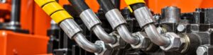
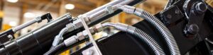
Choosing between SAE 100R1 vs 100R2 vs 100R16 requires more than comparing pressure ratings and the number of wire-braid layers. Hose inside diameter, fitting bore, flow rate, temperature, minimum bend radius, pressure impulses, routing, and crimp compatibility all affect system performance.
R1, R2, and R16 Are Not Three Quality Levels
SAE 100R1, SAE 100R2, and SAE 100R16 should not be treated as low-, medium-, and high-quality versions of the same hose.
Each type is designed around a different combination of pressure capability, reinforcement, outside diameter, flexibility, and installation requirements.

What Is SAE 100R1 Hose?
SAE 100R1 hose typically uses one high-tensile steel wire braid for reinforcement. Many products in this category may also meet corresponding 1SN requirements, but compliance must always be confirmed from the specific hose data sheet.
Its main advantages include:
- Lower weight
- Better flexibility
- Easier routing
- Less mechanical load on ports and fittings
- Smaller overall assembly weight
R1 is often suitable for medium-pressure hydraulic lines when the selected size meets the actual working pressure, surge pressure, temperature, and fluid compatibility requirements.
Its main limitation is that its pressure capability is generally lower than that of a comparable R2 hose. However, when R1 already meets the application requirements, replacing it with a stiffer two-wire hose may provide no practical benefit.
What Is SAE 100R2 Hose?
SAE 100R2 hose typically uses two high-tensile steel wire braids. Many products may also carry a 2SN designation, but the two standards should not be assumed to be identical without product-specific confirmation.
R2 is commonly selected for:
- Higher-pressure hydraulic circuits
- Heavy-duty mobile equipment
- Applications with significant pressure loads
- Circuits where one-wire hose does not provide sufficient pressure capacity
Its advantages include higher pressure capability across many common sizes and increased reinforcement for demanding hydraulic service.
However, R2 is usually heavier and less flexible than R1. This can create installation problems when:
- The hose is very short.
- The ports are misaligned.
- The available routing space is limited.
- The hose must move through a large operating range.
- The assembly is forced into position during installation.
A hose can meet the pressure requirement and still fail prematurely because of mechanical stress.
What Is SAE 100R16 Hose?
SAE 100R16 is generally considered a compact high-pressure hydraulic hose. Depending on the size and construction, it may use one or two wire braids.

Its typical advantages include:
- A more compact outside diameter
- A smaller minimum bend radius
- Easier routing in confined spaces
- Reduced assembly size
- Suitability for crowded mobile hydraulic systems
R16 is especially useful where a conventional high-pressure hose cannot be routed naturally without interfering with the frame, guards, moving parts, or adjacent components.
Its compact shape does not make it universally interchangeable with R1 or R2. The selected hose must be assembled with approved fittings, ferrules, and crimp specifications. Crimp dimensions from another hose series should never be copied simply because the outside diameters appear similar.
| Hose type | Typical reinforcement | Main advantage | Main limitation |
| SAE 100R1 | One steel wire braid | Light, flexible, and easy to route | Lower pressure capability in many comparable sizes |
| SAE 100R2 | Two steel wire braids | Higher pressure capability for demanding circuits | Heavier, stiffer, and more difficult to route |
| SAE 100R16 | One or two wire braids, depending on size and design | Compact construction and smaller bend radius | Requires careful hose, fitting, and crimp matching |
Why Can a Higher-Pressure Hose Make a Machine Slower?
A higher pressure rating only shows that the hose can withstand a specified pressure under defined conditions.
It does not show how efficiently the hose can carry the required flow.
If a replacement assembly has a smaller effective flow diameter, fluid velocity will increase. Higher velocity can increase pressure loss through the hose, fittings, elbows, adapters, and quick couplings.
The basic relationship is:
Flow rate = Flow area × Fluid velocity
For example, assume a hydraulic circuit carries 60 L/min.
| Effective inside diameter | Approximate velocity at 60 L/min |
| 12.7 mm | 7.9 m/s |
| 19.0 mm | 3.5 m/s |
Reducing the effective diameter from 19.0 mm to 12.7 mm more than doubles the fluid velocity.
The actual pressure loss depends on several factors:
- Hose inside diameter
- Hose length
- Fluid viscosity
- Oil temperature
- Internal surface characteristics
- Number and type of fittings
- Elbows and adapters
- Quick couplings
- Changes in flow direction
- Local restrictions
The hose series alone does not determine pressure loss. If two assemblies have the same effective inside diameter, fitting bore, length, and routing, choosing a higher-pressure hose does not automatically make the machine slower.
The problem begins when the replacement changes the effective flow path.
How Pressure Loss Becomes Heat

Hydraulic power lost across a restriction is converted primarily into heat.
A useful simplified relationship is:
Power loss (kW) = Pressure drop (bar) × Flow rate (L/min) ÷ 600
If a hose assembly carries 60 L/min and produces an 8 bar pressure drop:
8 × 60 ÷ 600 = 0.8 kW
Approximately 0.8 kW of hydraulic power is continuously converted into heat.
If the machine operates for six hours:
0.8 × 6 = 4.8 kWh
That is approximately 4.8 kWh of energy lost through heat generation.
The 8 bar value is only an example. Actual pressure loss must be measured or calculated for the specific hose, fluid, temperature, fittings, and operating conditions.
Installing a larger oil cooler may remove some of the additional heat, but it does not correct the restriction that created the heat.
A Fitting That Screws On May Still Be Too Restrictive
Thread size does not define the complete flow path.
A customer may request:
“One-half-inch hose, BSP fittings on both ends, one metre long, two wire braids.”
This information describes only part of the assembly. It does not confirm that the hose is suitable for the machine.
The following dimensions can be different even when the thread connection is the same:
- Hose nominal inside diameter
- Hose actual inside diameter
- Fitting insert bore
- Adapter bore
- Quick-coupling bore
- Valve-port passage
- Swivel or elbow passage
The smallest internal passage can become the main restriction in the circuit.
For example, a correctly sized hose may still perform poorly if it is connected through:
- A small-bore fitting insert
- An unnecessary reducing adapter
- A restrictive 90-degree elbow
- A contaminated quick coupling
- A partially opened valve
- An undersized motor case-drain connection
If one fitting, adapter, or coupling becomes noticeably hotter than the surrounding hose, it may indicate concentrated pressure loss at that location. Temperature alone is not a complete diagnosis, but it is a useful reason to investigate further.
When possible, measure pressure before and after the suspected restriction under the same load, flow, and oil-temperature conditions.
Is a Two-Wire Hose Always Safer Than a One-Wire Hose?
No. If a one-wire hose does not meet the required working pressure or pressure-impulse conditions, a suitable two-wire hose may be necessary.
However, if the selected R1 hose already satisfies the application requirements, installing R2 without checking the routing may introduce new risks.
Increased Side Load on the Port
A stiffer hose resists bending. If the fitting and port are not aligned, the hose may continuously pull against the connection.
This can increase stress on:
- Valve-block ports
- Threaded adapters
- Pump housings
- Tube fittings
- Flanges
- Welded connections
Insufficient Installation Space
A larger outside diameter may no longer fit the original clamps, guards, or routing channels.
Forcing the hose into the existing space can cause:
- Abrasion
- Flattening
- Twisting
- Contact with sharp edges
- Contact with hot surfaces
- Interference with moving parts
Sharp Bending Behind the Ferrule
The area immediately behind the ferrule should not be forced into a sharp bend.
A hose may have sufficient pressure capacity but still fail near the fitting because of repeated bending, tension, or incorrect routing. Over time, this can contribute to:
- Cover cracking
- Reinforcement fatigue
- Hose separation
- Leakage near the fitting
- Complete assembly failure
The correct decision is not simply “one wire or two wires.”
The correct sequence is:
- Confirm working pressure and pressure impulses.
- Confirm the required flow and inside diameter.
- Confirm temperature and fluid compatibility.
- Check minimum bend radius and routing space.
- Select the lightest and most flexible hose that safely satisfies all requirements.
Pressure, Return, Suction, Drain, and Pilot Lines Need Different Selection Logic
Not every hydraulic line should be selected in the same way.

Pressure Lines
Pressure lines must withstand normal working pressure, transient pressure, pressure impulses, fluid temperature, and external mechanical loads.
Both pressure rating and flow capacity are important.
Return Lines
Return lines may operate at relatively low average pressure, but they can carry high flow.
An undersized return hose, restrictive fitting, or small quick coupling can create backpressure, heat, seal problems, and reduced actuator performance.
A low pressure reading at the pump does not rule out a return-line restriction.
Suction Lines
Pump suction lines require special attention to vacuum resistance and collapse resistance.
A hose that has a high positive-pressure rating is not automatically suitable for suction service. A hose can be strong under internal pressure but still collapse under vacuum.
Suction applications generally require a hose specifically designed for vacuum or suction conditions.
Case-Drain and Leakage Lines
Hydraulic motor and pump case-drain lines often carry limited flow, but they may be highly sensitive to backpressure.
A restrictive drain hose or fitting can increase housing pressure and contribute to:
- Seal leakage
- High temperature
- Reduced component life
- Internal damage
Pilot Lines
Pilot circuits may use relatively small hoses, but pressure response and contamination control can be critical. Hose selection must match the control system requirements, not only the thread size.
Three Situations Where You Should Not Order Yet
1. You Know the Thread but Not the Line Function
Knowing that the assembly uses a particular thread does not reveal whether it is a pressure, return, suction, drain, or pilot line.
Identify the function first.
2. You Know the Maximum Pressure but Not the Flow
Pressure determines whether the hose can carry the load safely.
Flow and effective inside diameter influence velocity, pressure loss, and heat generation.
Without flow information, it is difficult to determine whether the selected hose and fittings are large enough.
3. The Hose, Fitting, Ferrule, and Crimp Data Have Not Been Confirmed
A hose assembly is a complete system consisting of:
- Hose
- Fitting insert
- Ferrule
- Crimp diameter
- Insertion depth
- Assembly procedure
- Inspection and testing
Components should not be mixed solely because they appear to fit together.
An incorrect crimp may pass an initial visual inspection and remain dry during a short test. It may later fail under pressure impulses, vibration, temperature cycles, or hose movement.
A Practical R1, R2, and R16 Selection Process
Use the following sequence before choosing a hose.
Step 1: Identify the Line Function
Determine whether the hose is used for pressure, return, suction, case drain, pilot control, or another function.
Step 2: Confirm the Fluid
Check compatibility with the hydraulic oil, water-based fluid, biodegradable fluid, or other medium used in the system.
Step 3: Confirm the Temperature
Record both fluid temperature and surrounding temperature. Also check for nearby exhaust components, engines, furnaces, or other heat sources.
Step 4: Record Working and Peak Pressure
Do not select a hose based only on the pressure observed during light operation.
Consider:
- Normal working pressure
- Relief-valve setting
- Transient pressure
- Pressure impulses
- Test pressure requirements
Step 5: Determine Continuous and Peak Flow
Use the maximum expected flow for the specific line. Return flow may differ from pump delivery because of cylinder area ratios, accumulators, or combined circuit operation.
Step 6: Select the Required Inside Diameter
Choose the inside diameter according to flow, acceptable velocity, line function, fluid viscosity, and allowable pressure loss.
Do not assume that two hoses with the same thread size have the same internal flow area.
Step 7: Check the Complete Flow Path
Review the bore of every component:
- Hose
- Fitting inserts
- Elbows
- Adapters
- Quick couplings
- Valves
- Manifold ports
The smallest passage may control the pressure loss.
Step 8: Check Routing and Minimum Bend Radius
Confirm that the hose can follow its natural curve without twisting, stretching, flattening, or bending sharply behind the ferrule.
Step 9: Confirm the Approved Assembly System
Use compatible hose, fittings, ferrules, and crimp specifications. Record the correct crimp diameter and assembly procedure.
Step 10: Verify the Installed Assembly
After installation:
- Inspect the routing.
- Operate the equipment through its full movement.
- Check for twisting and rubbing.
- Compare pressure before and after suspected restrictions.
- Monitor oil and component temperatures.
- Inspect for leakage under operating conditions.
Final Conclusion
The correct hydraulic hose must satisfy more than pressure. It must also provide the required flow, remain compatible with the fluid and temperature, fit the available space, follow the machine’s movement, and use a verified fitting and crimp system.
A hose that does not burst can still be wrong. If it restricts flow, creates backpressure, bends below its minimum radius, or transfers excessive force to the port, it can reduce machine performance and shorten component life.
Frequently Asked Questions
Can R2 Directly Replace R1?
Sometimes, but not automatically. The R2 hose must have the correct inside diameter, pressure rating, temperature range, fluid compatibility, bend radius, fitting system, and routing space. Its additional stiffness and outside diameter may create installation problems.
Can R16 Replace R2?
It may be possible when the selected R16 size meets all pressure, temperature, flow, impulse, and compatibility requirements. The fittings and crimp dimensions must be approved for the selected R16 hose.
Does the Same Thread Size Mean the Same Hose Size?
No. Thread size describes the connection. Hose inside diameter and fitting bore must be checked separately.
Can R2 Be Used as a Suction Hose?
A high positive-pressure rating does not prove that a hose can withstand vacuum without collapsing. Use a hose specifically rated for the required suction conditions.
Why Does a Fitting Become Hotter Than the Hose?
A local temperature increase may indicate concentrated pressure loss caused by a small bore, partial blockage, sharp flow transition, or restrictive coupling. Confirm the cause through inspection and pressure measurements.
Is a Larger Hose Always Better?
No. An unnecessarily large hose increases cost, weight, oil volume, and installation space. The goal is to choose a size that provides acceptable velocity and pressure loss while meeting all mechanical and safety requirements.