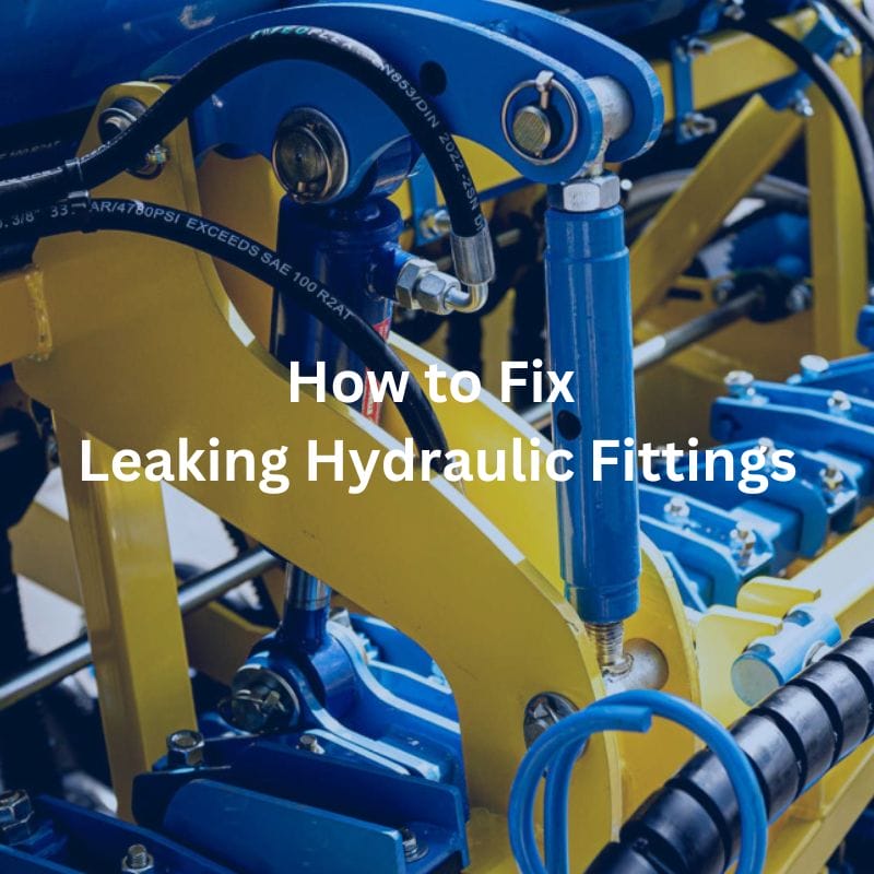
How to Fix Leaking Hydraulic Fittings
Table of Contents
Introduction
Are you frustrated with leaking hydraulic fittings? Don’t worry—you’re not alone. Hydraulic leaks are a common issue that can lead to significant downtime, reduced system efficiency, and increased maintenance costs. These leaks can arise from a variety of causes, including improper installation, component wear, incorrect torque settings, or physical damage. Understanding the basics of hydraulic fittings and their maintenance can save you time, money, and the hassle of frequent repairs. This guide aims to equip you with the knowledge and skills necessary to identify, diagnose, and fix leaks in hydraulic fittings.
How to Fix Leaking Hydraulic Fittings?
To fix a leaking hydraulic fitting, firstidentify the type of fitting you are dealing with. Next, inspect the fitting and surrounding components for any signs of damage or wear, including cracks, worn seals, or thread damage. Carefully clean the area to ensure no debris interferes with the repair. Tighten the fitting to the manufacturer’s recommended torque specification, avoiding over-tightening, which can cause further damage. If any components are damaged, replace them with high-quality, compatible parts to ensure a proper seal and prevent future leaks.
Read on to learn the step-by-step process for diagnosing and fixing leaks in hydraulic fittings, including detailed instructions on how to identify the source of the leak, the necessary tools and materials, and common mistakes to avoid.
Types of Hydraulic Fittings
Different hydraulic systems use various types of fittings, each designed for specific applications and pressure requirements. Understanding these types is essential for effective maintenance and repair, as choosing the right fitting can significantly impact the system’s performance and longevity.
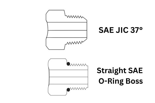
Flared Fittings
Flared fittings involve flaring the end of a tube to create a conical shape, which increases the surface area for sealing. This design provides a robust and reliable connection capable of withstanding high pressures. Flared fittings are commonly used in applications where high-pressure resistance and mechanical strength are critical, such as in aerospace and military hydraulic systems. The flaring process ensures a tight fit, reducing the risk of leaks and enhancing the durability of the connection.

O-ring Face Seal Fittings
O-ring face seal fittings use an O-ring placed in a groove on the fitting’s face to create a seal when the fitting is tightened against a flat surface. This design is highly effective in preventing leaks and is suitable for high-pressure systems, such as those found in industrial machinery and heavy equipment. The O-ring compresses to fill any gaps, providing a reliable seal even under varying pressure conditions.
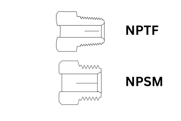
Tapered Thread Fittings
Tapered thread fittings rely on the threads themselves to create a seal. As the fitting is tightened, the tapered threads compress, creating a pressure-tight connection. Thread sealant or tape is often applied to the threads to enhance the seal. These fittings are commonly used in lower-pressure applications and are appreciated for their simplicity and ease of installation. However, care must be taken to avoid over-tightening, which can damage the threads and compromise the seal.
Bite-Type Fittings
Bite-type fittings feature a sharp edge that bites into the tube when the fitting is tightened, creating a secure seal. This design is known for its ease of installation and reliable sealing capability. Bite-type fittings are often used in medium to high-pressure applications, such as in hydraulic and pneumatic systems. The biting mechanism ensures a firm grip on the tubing, preventing leaks and providing a durable connection. These fittings are particularly useful in systems that experience vibration or dynamic loading, as the bite provides additional stability.
Step-by-Step Guide to Fixing Leaking Hydraulic Fittings
Step 1 – Identify the Leak Source
Identifying the exact source of a hydraulic leak is the first and most crucial step in fixing the issue. A systematic approach ensures you do not miss any potential problem areas and helps in planning the repair effectively.

Visual Inspection
Begin with a thorough visual inspection of the hydraulic system. Look for visible signs of oil or hydraulic fluid around fittings, hoses, cylinders, and other components. Fluid accumulation, oil stains, or wet areas are clear indicators of a leak.
Focus on Connection Points
Leaks often occur at connection points where fittings connect to hoses or other machinery parts. These junctions are prone to wear and tear due to constant pressure changes and mechanical stress. Pay close attention to these areas, as they are the most common sources of leaks. Ensure that all connections are properly seated and that there are no visible gaps or misalignments.
Check for Signs of Wear and Tear
Inspect the fittings, hoses, and surrounding components for signs of wear and tear. Look for cracks, abrasions, or deformities in the hoses and fittings. These signs can indicate that the material has weakened over time and is prone to leaking. Pay attention to any discoloration or changes in texture, as these can also signal material degradation.
Listen for Unusual Sounds
In some cases, leaks may not be immediately visible but can be detected by sound. Listen for unusual hissing or whistling noises that may indicate escaping air or fluid. These sounds can help you pinpoint leaks that are otherwise difficult to detect visually. Use a mechanic’s stethoscope if necessary to amplify these sounds and locate the source more accurately.
Use a Leak Detection Fluid
If the visual inspection does not reveal the leak, consider using a leak detection fluid. These fluids are designed to highlight leaks by changing color when they come into contact with hydraulic fluid. Apply the detection fluid around suspected areas and look for color changes that indicate a leak. This method is particularly useful for detecting small or slow leaks that are not immediately apparent.
Step 2 – Depressurize the System
Before working on any part of the hydraulic system, ensuring it is fully depressurized is crucial to prevent injury and further damage. Hydraulic systems operate under high pressure, and attempting repairs without relieving this pressure can result in serious accidents.
Some hydraulic systems are equipped with pressure relief valves or bleed screws designed specifically for this purpose. Open these valves or screws slowly to allow any remaining pressure to escape. Place a container under the bleed point to catch any hydraulic fluid that may be expelled. This step helps ensure that the system is completely depressurized and safe to work on.
Double-check that the system is fully depressurized before proceeding with any repairs. Carefully inspect the system to ensure no pressure remains. Touch the hoses and fittings to make sure they are not pressurized; they should feel flexible and not rigid. Additionally, use a pressure gauge if available to confirm that there is no residual pressure in the system.
Step3 – Inspect the Fitting and Components
Carefully inspecting the fitting and its associated components is essential for identifying the cause of leaks and ensuring that repairs are effective. A thorough examination helps pinpoint areas of wear, damage, or misalignment that could compromise the integrity of the hydraulic system.
Visual Inspection
Start by closely inspecting the hydraulic fitting itself. Look for any visible signs of wear or damage, such as cracks, dents, or deformation. Pay special attention to the areas where the fitting connects to hoses or other components. If the fitting appears damaged or worn, it will need to be replaced to ensure a proper seal.
Check for Misalignment
Misalignment between fittings and hoses can cause leaks and stress on the system. Ensure that the fitting is correctly aligned with the corresponding hose or component. Misalignment can often be visually identified by uneven wear patterns or gaps between connecting parts. Correcting misalignment is crucial for maintaining a secure connection and preventing future leaks.
Inspect the Threads
Carefully inspect the threads on the fitting and the mating component. Look for signs of stripping, cross-threading, or other damage. Damaged threads can prevent the fitting from sealing properly, leading to leaks. If the threads are worn or damaged, consider using a thread file to clean them up or replacing the fitting entirely.
Evaluate Seals and O-rings
Examine the seals, O-rings, and other sealing components for signs of wear or damage. Look for cracks, tears, or deformation in these parts. Seals and O-rings are critical for maintaining a leak-free connection, and even small imperfections can lead to significant leaks. Replace any seals or O-rings that show signs of damage or wear.
Inspect Mating Surfaces
Ensure that the mating surfaces of the fitting and the components it connects to are clean and free from nicks, scratches, or other imperfections. Even minor surface defects can prevent a proper seal, causing leaks. Use a clean cloth to wipe down the surfaces and a magnifying glass to inspect for minute defects. If you find any surface damage, consider smoothing it out with fine-grit sandpaper or replacing the affected component.
Check for Corrosion
Hydraulic systems are often exposed to harsh environments, which can lead to corrosion. Inspect the fittings and components for any signs of rust or corrosion, which can weaken the material and lead to leaks. If corrosion is present, clean the affected area thoroughly and consider applying a corrosion inhibitor.
Step 4 – Replace Damaged Parts
When you find any damaged parts during your inspection, it’s crucial to replace them with new, compatible components to ensure the hydraulic system functions correctly. This step is vital for maintaining the integrity of the system and preventing future leaks.
Source Compatible Replacement Parts
Ensure that the replacement parts are compatible with your specific hydraulic system. Compatibility is crucial for maintaining the system’s integrity and performance. Check the following specifications:
Pressure Ratings: Ensure that the replacement parts can withstand the operating pressure of your hydraulic system. Using parts with incorrect pressure ratings can lead to failures and leaks.
Material Compatibility: Verify that the materials used in the replacement parts are compatible with the hydraulic fluid and the overall system. Incompatible materials can degrade over time, leading to leaks and system failures.

Step 5 – Reassemble and Tighten the Fitting
Reassembling and tightening the fitting properly is crucial to ensuring a leak-free hydraulic system. Follow these detailed steps to align and secure the components correctly, and use the appropriate tools and techniques to achieve the recommended torque specifications.
Position the Fitting
Place the fitting in its designated position, ensuring that it aligns perfectly with the mating component. Take your time to adjust the parts so that they fit together smoothly without forcing them into place.
Insert Seals and O-rings
Carefully insert any seals, O-rings, or other sealing components into their respective grooves. Ensure that these elements are correctly positioned and not twisted or out of place, as improper placement can compromise the seal.
Hand-Tighten Initially
Begin by hand-tightening the fitting to ensure that the threads engage properly. This initial step helps in preventing cross-threading and allows for better control during the final tightening process.
Use a Torque Wrench

Once the fitting is hand-tightened and all components are aligned, use a torque wrench to tighten the fitting to the manufacturer’s recommended torque specifications. This tool is essential for applying the correct amount of force without over-tightening or under-tightening.
Tighten Gradually
Tighten the fitting gradually, applying consistent pressure. It’s best to use a methodical approach, such as tightening the fitting a little at a time in stages. This ensures even pressure distribution and reduces the risk of over-tightening.
Avoid Over-Tightening
Over-tightening can damage the fitting and threads, leading to potential leaks and component failure. Be mindful of the torque wrench settings and stop tightening once the specified torque is reached. If using a click-type torque wrench, listen for the click that indicates the correct torque has been applied.
Check for Proper Engagement
Ensure that the fitting is properly engaged with the mating component. There should be no gaps or misalignments. If you notice any issues, depressurize the system and recheck the alignment and tightening process.
Step 6 – Test the Repair
Testing the repair is a critical step to ensure that the hydraulic system is functioning correctly and that no leaks are present. Proper testing helps verify the integrity of the repair and prevents future issues. Follow these steps to test the repaired fitting thoroughly.
Gradually Pressurize the System
After reassembling and tightening the fitting, gradually pressurize the hydraulic system. This controlled pressurization allows you to monitor the system closely for any signs of leaks or abnormalities. Start by turning on the hydraulic power at a low setting, and slowly increase the pressure to the system’s normal operating level.
Inspect for Leaks
Carefully inspect the repaired fitting and the surrounding area for any signs of hydraulic fluid leakage. Look for droplets, wet spots, or a slow seepage of fluid around the fitting. Use a clean, dry cloth to wipe the area and check for any fresh fluid.
Use Leak Detection Methods
In addition to visual inspection, consider using leak detection methods to ensure no leaks are present. These methods can include:
Leak Detection Fluid: Apply a leak detection fluid around the fitting and observe any color changes indicating a leak.
UV Dye: Add a UV dye to the hydraulic fluid and use a UV light to detect any escaping fluid, which will glow under the light.
Pressure Gauge: Attach a pressure gauge to monitor the system pressure. A drop in pressure could indicate a leak somewhere in the system.
Operational Test
After confirming that there are no leaks under static pressure, perform an operational test by running the hydraulic system through its normal operations. This test helps ensure that the fitting maintains its integrity under dynamic conditions, such as changes in pressure and movement of hydraulic components. Observe the system for any new signs of leakage during operation.
Common Mistakes to Avoid
Over-tightening fittings: This can damage threads and cause leaks. Always use a torque wrench and follow the manufacturer’s torque specifications.
Using incompatible replacement parts: Mismatched parts can fail under pressure, leading to leaks. Ensure all replacement parts are specified for your system.
Neglecting to clean the fitting and surrounding area thoroughly: Dirt and debris can compromise the seal and lead to leaks. Always clean the area thoroughly before beginning repairs.
Conclusion
In summary, fixing leaking hydraulic fittings involves identifying the leak source, depressurizing the system, cleaning and inspecting the fitting, replacing damaged parts, reassembling and tightening the fitting to the correct torque, and thoroughly testing the repair. Regular maintenance is crucial to prevent future leaks and ensure the longevity and efficiency of your hydraulic system. By following these steps meticulously, you can maintain a reliable and leak-free hydraulic system. For further information and detailed guides on hydraulic maintenance, consider exploring Topa’s additional resources and consulting professional services if needed.
FAQ
What are the common causes of hydraulic fitting leaks?
Common causes include improper installation, worn or damaged seals, over-tightening or under-tightening fittings, and using incompatible parts.
How do I identify the source of a hydraulic leak?
Inspect the system for visible signs of oil or fluid around fittings and hoses, wipe down suspected areas, and use leak detection fluids or UV dyes to pinpoint the leak.
What tools do I need to fix a leaking hydraulic fitting?
You will need a torque wrench, replacement seals and fittings, cleaning supplies, and safety equipment like gloves and eye protection.
How do I depressurize a hydraulic system before making repairs?
Turn off the hydraulic power, operate control valves to release pressure, and use bleed valves to ensure all pressure is relieved.
What should I do if the fitting continues to leak after tightening?
Depressurize the system again, check for proper alignment and seal integrity, and retighten to the correct torque. If the leak persists, inspect for damaged parts and replace them as needed.
Why is regular maintenance important for hydraulic systems?
Regular maintenance helps identify and address potential issues early, preventing leaks and ensuring the system operates efficiently and reliably.


