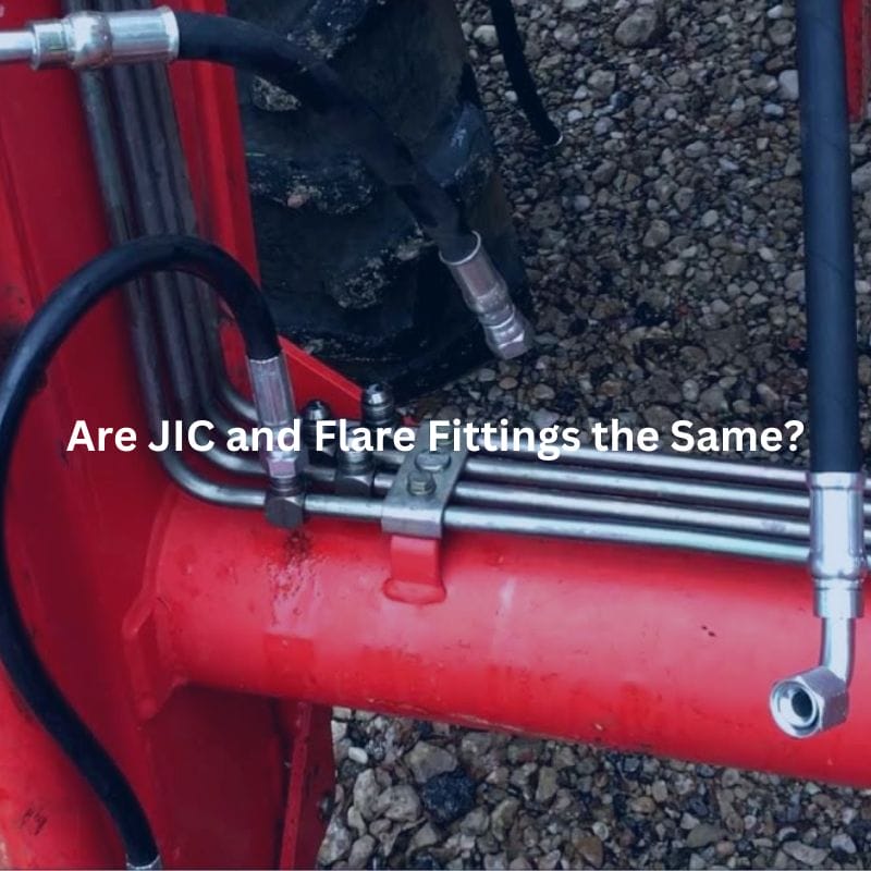
Are JIC and Flare Fittings the Same?
Introduction
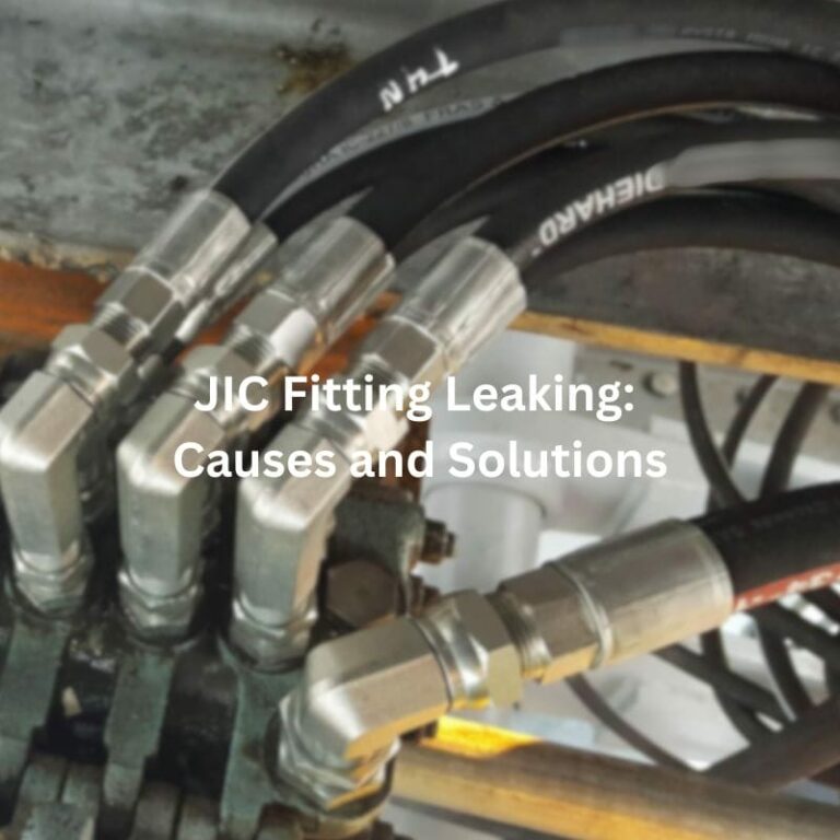
JIC fittings, known for their robust design, are commonly found in high-pressure applications, while flare fittings, which come in various angles, are valued for their versatility and ease of installation. Both play vital roles in ensuring the integrity and functionality of hydraulic systems, and knowing when to use each can significantly impact the efficiency and reliability of your operations. This article aims to shed light on the distinctions and commonalities between JIC fittings and flare fittings, two widely used types in the industry.
Understanding JIC Fittings
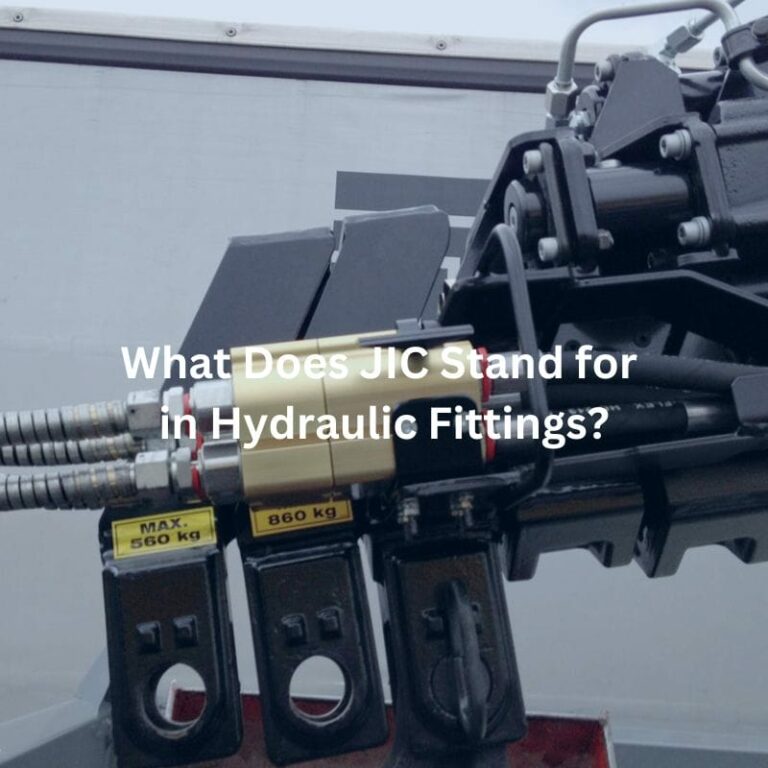
What JIC Stands For
JIC stands for Joint Industry Council, a term that originates from the collaboration between various industry stakeholders to standardize fitting specifications. This standardization ensures compatibility and reliability across different manufacturers and applications.
History and Development of JIC Fittings
JIC fittings were developed to meet the needs of industries requiring reliable, high-pressure fittings for hydraulic systems. Initially created for the military during World War II, these fittings provided a solution for high-pressure hydraulic applications, ensuring robust and leak-free connections. Over time, their use expanded into various civilian industries, leading to their widespread adoption and standardization.

Design and Specifications
Detailed Description of the Design:
JIC fittings are characterized by their 37-degree flare seating surface, which provides a metal-to-metal seal. This design ensures a strong and reliable connection that can withstand high pressures and vibrations. The fittings consist of three main components: the fitting body, the nut, and the sleeve. The body has a male or female end that connects to the corresponding part, while the nut and sleeve secure the tubing or hose in place.
Standard Specifications and Dimensions (SAE J514):
JIC fittings adhere to the SAE J514 standard, which defines the dimensions, materials, and performance requirements for 37-degree flare fittings. These specifications ensure interchangeability and compatibility across different manufacturers and applications. The fittings are available in various sizes, typically ranging from 1/8 inch to 2 inches in diameter, to accommodate different system requirements.
Common Applications
Industries That Commonly Use JIC Fittings:
JIC fittings are prevalent in industries that demand high-performance hydraulic systems. Some of the key sectors include:
Automotive: Used in brake lines, fuel lines, and hydraulic clutch systems.
Aerospace: Essential for hydraulic and fuel systems in aircraft due to their reliability and ability to withstand high pressures.
Heavy Machinery: Employed in construction, agricultural, and industrial machinery where robust hydraulic connections are crucial.
Types of Systems and Fluids Compatible with JIC Fittings:
JIC fittings are compatible with a wide range of hydraulic systems and fluids, including:
Hydraulic Oil: Commonly used in various hydraulic machinery and systems.
Fuel Systems: Suitable for gasoline, diesel, and other fuels in automotive and aerospace applications.
Lubrication Systems: Used in industrial machinery to ensure smooth operation and reduce wear and tear.
Refrigeration Systems: Compatible with refrigerants used in HVAC and refrigeration equipment.
Understanding Flare Fittings
Definition and Origin
Flare fittings are a type of compression fitting used to create a tight, leak-free seal in fluid systems. They were developed to provide reliable connections for various applications, particularly where soldering or welding is impractical. Historically, flare fittings have been essential in plumbing, HVAC, and automotive systems due to their ability to withstand high pressure and temperature variations. The design allows for a durable and reusable connection, which has made them a staple in many industries.
Different Types of Flare Fittings
45-Degree Flare Fittings: Commonly used in plumbing and refrigeration, these fittings are standardized under SAE J512. The 45-degree angle provides a reliable seal for systems with moderate pressure requirements.
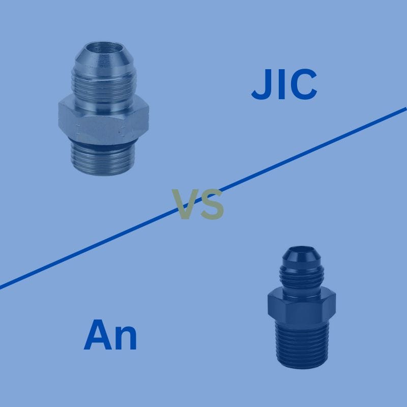
37-Degree Flare Fittings: Often referred to as AN (Army-Navy) or JIC fittings, these are used in high-pressure applications. The 37-degree flare angle ensures a strong seal, making them suitable for hydraulic and fuel systems.

Design and Specifications
Detailed Description of the Design:
Flare fittings consist of a fitting body, a flare nut, and a sleeve or ferrule. The fitting body has a conical seat that matches the flare angle of the tubing. The flare nut is tightened over the flared end of the tube, pressing it against the conical seat of the fitting body to create a metal-to-metal seal. This design ensures a secure, leak-free connection that can be easily disassembled and reassembled without damaging the tubing.
Standard Specifications and Dimensions:
45-Degree Flare Fittings (SAE J512): These fittings adhere to the SAE J512 standard, which defines the dimensions and performance requirements for 45-degree flare connections. They are typically available in sizes ranging from 1/8 inch to 2 inches in diameter.
37-Degree Flare Fittings (SAE J514): These fittings follow the SAE J514 standard, which specifies the dimensions and performance criteria for 37-degree flare fittings. They come in various sizes, from 1/8 inch to 2 inches, to accommodate different system needs.
Types of Systems and Fluids Compatible with Flare Fittings:
Flare fittings are compatible with a wide range of systems and fluids, including:
Water and Gas Lines: Common in plumbing systems for both residential and commercial applications.
Refrigerants: Used in HVAC and refrigeration systems to handle various types of refrigerants.
Hydraulic Fluids: Suitable for hydraulic systems in automotive and aerospace applications.
Fuel Systems: Compatible with gasoline, diesel, and other fuels in automotive and industrial systems.
Key Differences Between JIC and Flare Fittings
Angle and Design
The primary difference between JIC and standard flare fittings lies in the angle of the flare. JIC fittings feature a 37-degree flare, while standard flare fittings typically have a 45-degree flare. This angle difference is crucial because it affects how the fittings mate and seal with their corresponding counterparts.
Impact of Angle on Compatibility and Sealing:
Compatibility: Due to the different angles, 37-degree JIC fittings cannot be directly connected to 45-degree flare fittings without an adapter. Using mismatched fittings can result in poor sealing and potential leaks.
Sealing: The 37-degree flare used in JIC fittings creates a tighter seal under high-pressure conditions compared to the 45-degree flare. This makes JIC fittings more suitable for high-pressure hydraulic systems where reliable sealing is critical. The 45-degree flare fittings, while suitable for moderate pressures, may not provide the same level of sealing in high-pressure applications.
Thread Types and Dimensions
Differences in Thread Design and Sizes:
Thread Design: JIC fittings typically use UNF (Unified National Fine) threads, which have a higher thread pitch and provide a tighter fit, enhancing their sealing capabilities. Standard 45-degree flare fittings often use NPT (National Pipe Thread) or SAE (Society of Automotive Engineers) threads, which have a tapered design to help create a seal.
Thread Sizes: JIC fittings are available in a wide range of sizes, from 1/8 inch to 2 inches, and their threads are designed to match these specific sizes. Standard flare fittings also come in various sizes but may have different thread configurations depending on the application.
Implications for Installation and Interchangeability:
Installation: The difference in thread types means that installation techniques and tools may vary between JIC and standard flare fittings. JIC fittings often require precise torque specifications to ensure a proper seal, while 45-degree flare fittings may be more forgiving in terms of installation torque.
Interchangeability: Due to the differences in thread design and flare angles, JIC and standard flare fittings are not interchangeable without the use of specific adapters. Attempting to interchange these fittings without proper adapters can lead to leaks and system failures.

Material and Construction
Common Materials Used for Each Type:
JIC Fittings: Commonly made from materials such as carbon steel, stainless steel, and brass. These materials are chosen for their strength, corrosion resistance, and suitability for high-pressure applications.
Standard Flare Fittings: Often made from brass, which is corrosion-resistant and suitable for moderate-pressure applications. Steel and stainless steel are also used, particularly in applications requiring higher strength and durability.
Durability and Suitability for Different Environments:
Durability: JIC fittings, especially those made from stainless steel, are highly durable and can withstand harsh environments, including high-pressure and high-temperature conditions. Brass JIC fittings are suitable for less demanding environments but still offer good durability.
Suitability: The choice of material impacts the suitability of the fittings for different environments. Stainless steel JIC fittings are ideal for corrosive environments, such as marine or chemical processing industries. Brass flare fittings are suitable for plumbing, HVAC, and refrigeration systems where moderate pressure and corrosion resistance are required.
Compatibility and Interchangeability
When They Can Be Interchanged
Situations Where JIC and 37-Degree Flare Fittings Are Interchangeable:
JIC fittings and 37-degree flare fittings (often AN fittings) are functionally similar because they both use a 37-degree flare. This similarity allows for interchangeability in certain situations:
Same Flare Angle: Both JIC and 37-degree AN fittings have the same flare angle, which means they can create a proper seal when connected.
Thread Compatibility: JIC and 37-degree AN fittings generally use the same thread types (UNF threads), making them mechanically compatible.
Low to Moderate Pressure Applications: In situations where the pressure requirements are not extreme, JIC and AN fittings can often be interchanged without compromising system integrity.
Risks and Considerations When Interchanging:
Material Differences: Ensure that the materials of the fittings being interchanged are compatible with the fluid and the operating environment. For example, mixing brass with stainless steel in corrosive environments can lead to galvanic corrosion.
Pressure Ratings: Verify that the pressure ratings of the interchanged fittings match the system requirements. Although the angles are the same, the fittings may have different pressure tolerances.
Manufacturer Specifications: Always check manufacturer specifications to ensure that the fittings meet the required standards for the specific application. Not all 37-degree fittings are manufactured to the same quality and tolerance standards.
When They Cannot Be Interchanged
Specific Cases Where Interchangeability Is Not Recommended:
Different Flare Angles: JIC (37-degree) fittings cannot be interchanged with standard 45-degree flare fittings. The difference in flare angles will not allow for a proper seal, leading to potential leaks.
Thread Incompatibility: If the fittings use different thread types (e.g., UNF vs. NPT), they should not be interchanged. Even if the flare angles match, the thread mismatch will prevent proper connection.
High-Pressure Applications: In high-pressure systems, even small differences in manufacturing tolerances and material strength can lead to failures. It is essential to use fittings specifically rated for high-pressure applications.
Potential Issues with Compatibility:
Leakage: The most common issue when incompatible fittings are used is leakage. Mismatched angles or threads can create gaps that allow fluid to escape, reducing system efficiency and potentially causing damage.
Mechanical Failure: In high-pressure or high-vibration environments, improper fitting interchange can lead to mechanical failure. This can result in catastrophic system failure, posing safety risks and leading to costly repairs.
Corrosion and Wear: Using incompatible materials can accelerate corrosion and wear, reducing the lifespan of the fittings and the overall system. For example, using steel fittings in a corrosive environment intended for stainless steel fittings can result in rapid degradation.
Choosing the Right Fitting for Your Needs
Pressure
High-Pressure Systems: For applications that operate under high pressure, such as hydraulic systems in heavy machinery or aerospace, JIC fittings are often preferred due to their robust design and ability to maintain a tight seal under extreme conditions.
Moderate-Pressure Systems: For systems with moderate pressure requirements, both JIC and standard 45-degree flare fittings can be suitable. It’s essential to verify the pressure ratings of the fittings to ensure they match the system’s needs.
Temperature
High-Temperature Environments: In applications exposed to high temperatures, such as certain industrial processes or engine compartments, stainless steel JIC fittings are ideal due to their excellent thermal stability and resistance to heat.
Standard Temperature Ranges: For standard temperature applications, brass flare fittings are often sufficient and provide good performance at a lower cost.
Type of Fluid
Hydraulic Fluids: For hydraulic systems, JIC fittings are highly suitable due to their ability to withstand high pressures and provide leak-free connections. They are compatible with various hydraulic fluids, including oil and water-based fluids.
Fuel and Refrigerants: In fuel systems and refrigeration applications, both 37-degree JIC and 45-degree flare fittings can be used. However, the compatibility of the fitting material with the specific fluid is crucial to prevent corrosion and ensure long-term reliability.
Water and Gas Lines: Brass 45-degree flare fittings are commonly used in plumbing applications for water and gas lines due to their corrosion resistance and ease of installation.
Conclusion
In summary, JIC and flare fittings, while similar in some aspects, differ significantly in their design, angle, thread types, and applications. We encourage you to evaluate your current fittings and determine if they meet your system’s demands. If you find any shortcomings or are planning new installations, consider whether switching to JIC or flare fittings would enhance your system’s performance. For further information or personalized consultation, feel free to reach out to our team of experts who are ready to assist you in making informed decisions for your hydraulic and fluid system.
FAQ
The primary difference is the flare angle: JIC fittings have a 37-degree flare, while standard flare fittings typically have a 45-degree flare. This affects their compatibility and sealing capabilities in various applications.
No, they cannot be used interchangeably due to the difference in flare angles. Using mismatched fittings can lead to poor sealing and potential leaks.
JIC fittings are widely used in industries such as automotive, aerospace, and heavy machinery, where high-pressure hydraulic systems are common.
45-degree flare fittings are commonly used in plumbing, HVAC, and refrigeration systems due to their moderate pressure capabilities and ease of installation.
JIC fittings are compatible with a wide range of fluids, including hydraulic oil, fuel, and lubricants. However, it’s important to ensure the material of the fitting is suitable for the specific fluid and operating environment.
To choose the right fitting, consider factors such as pressure, temperature, type of fluid, and compliance with industry standards. Consulting with experts and referring to manufacturer specifications can also help in making an informed decision.


