Signs Your Ball Valve Off Position Is Causing System banner

Signs Your Ball Valve Off Position Is Causing System Issues

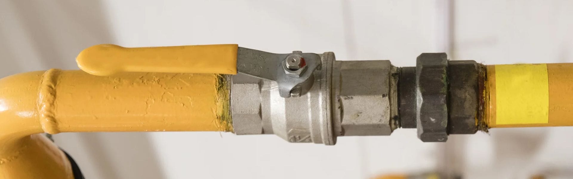
Ball valves are critical components in fluid systems, ensuring precise regulation of flow and pressure for liquids or gases. Proper positioning of these valves not only supports seamless operation and optimal energy efficiency but also promotes a safe working environment. However, even slight misalignment can disrupt the system, leading to inefficiencies, hazards, and costly repairs. Misaligned or stuck ball valves can cause sudden pressure drops, reduced flow, visible leaks, and long-term damage to equipment.

Key Symptoms of a Ball Valve Off Position

Unexplained Pressure Loss Across the System

One of the first signs of a ball valve being in the off position is a sudden and unexplainable drop in system pressure. In a fluid system, consistent pressure is vital for maintaining the flow and ensuring all components work seamlessly. When the ball valve is misaligned, it can partially or fully block the passage, creating resistance that disrupts the pressure balance. This not only reduces the system’s efficiency but also forces pumps and other equipment to work harder, leading to increased wear and energy consumption. Regular monitoring of pressure levels can help you catch this symptom early.

Sudden Reduction in Flow Rate or Blockages

A misaligned ball valve can significantly restrict the flow of liquid or gas through the system. You might notice a sudden reduction in flow rate or, in severe cases, complete blockages that halt operations altogether. This can be particularly problematic in industrial settings where precise flow rates are critical to production processes. A reduction in flow often indicates that the valve is not in the proper position, either due to wear, mechanical failure, or improper handling during maintenance. Promptly inspecting and adjusting the valve can restore normal operation and prevent further complications.

Ball Valve Off Position

Visible Leaks at Valve Joints and Seals

Leaks around the joints and seals of a ball valve are another telltale sign of an off-position valve. When the valve isn’t properly aligned, it can place uneven pressure on the seals, causing them to wear out prematurely or fail entirely. These leaks can lead to fluid wastage, contamination, or even safety hazards, especially in systems handling hazardous or high-pressure materials. Inspecting for visible leaks and checking the alignment of the valve can help mitigate these risks before they escalate into more serious issues.

Common Causes of Improper Ball Valve Positioning

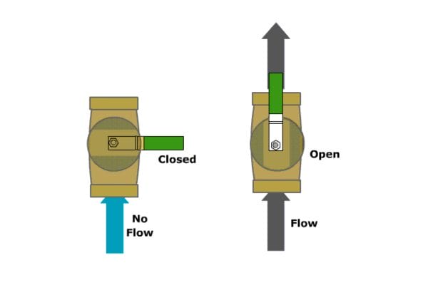
Misaligned Valve Handles: A Silent Culprit

One of the most frequent causes of improper ball valve positioning is misaligned handles. Over time, wear, user errors, or even accidental bumps can move the handle slightly out of its intended position. Though this may seem insignificant, even minor misalignment can disrupt the valve’s internal mechanisms, leading to partial or complete flow obstruction. In industrial settings, where precision is crucial, these small errors can cascade into larger issues, such as fluctuating system performance or safety hazards. Regular inspections and clearly labeled handles can help prevent this common problem.

Wear and Tear Leading to Valve Misalignment

As with any mechanical component, ball valves are subject to wear and tear over time. Prolonged exposure to high pressures, temperature fluctuations, and corrosive substances can degrade the internal parts of the valve, causing it to lose its alignment. A common result is uneven sealing or incomplete closure, which compromises the system’s efficiency and integrity. Scheduled maintenance is essential to identify and replace worn-out components before they lead to costly downtime or accidents.

External Factors: Vibrations and Incorrect Installation

External factors such as excessive vibrations or improper installation are often overlooked but can be significant contributors to valve misalignment. Vibrations from nearby machinery can loosen valve components or shift them out of position, especially in dynamic industrial environments. Similarly, incorrect installation—such as failing to secure the valve properly or misaligning it during setup—can lead to immediate or progressive alignment issues. Addressing these problems requires following precise installation protocols and using vibration-dampening supports where necessary.

How Ball Valve Misalignment Disrupts Fluid Flow

Understanding Pipeline Flow Disruption

Ball valve misalignment can severely disrupt fluid flow within a pipeline system. A misaligned valve creates an obstruction in the flow path, leading to increased turbulence and resistance. This disruption not only reduces efficiency but can also cause uneven pressure distribution throughout the system. Over time, these irregularities place extra strain on pumps and other components, accelerating wear and potentially causing system-wide failures. Furthermore, flow disruption can result in erratic operation in downstream equipment, impacting overall performance and productivity. Maintaining precise valve alignment is essential to ensure smooth and consistent fluid flow.

Identifying Signs of Fluid Flow Obstruction

Spotting fluid flow obstructions early can prevent costly repairs and downtime. Common indicators include noticeable drops in pressure at specific pipeline sections, uneven flow rates, and increased energy consumption by pumps. In some cases, operators may hear unusual noises, such as whistling or hammering, caused by turbulence around the obstruction. Visual inspections of the valve area might also reveal wear, residue build-up, or physical damage contributing to the blockage. Regular system diagnostics, coupled with the use of flow meters and pressure sensors, can help detect these signs and address valve misalignment promptly, safeguarding system performance.

Mechanical System Inefficiencies Triggered by Valve Misalignment

Increased Energy Usage Due to Flow Resistance

When a ball valve is misaligned, it disrupts the smooth flow of fluid through the pipeline, creating unnecessary resistance. This flow resistance forces pumps, compressors, or other system components to work harder to maintain the desired output. Over time, this additional effort translates to increased energy consumption, driving up operational costs significantly. In industrial systems, where energy expenses form a considerable part of the budget, even a small misalignment can result in substantial financial losses over extended periods.

Moreover, the inefficiency caused by misalignment often leads to overheating of pumps and motors, further accelerating wear and reducing the lifespan of these critical components. Increased energy usage is not just a financial burden but also an environmental concern, as it contributes to higher carbon emissions. Addressing valve misalignment promptly through routine inspections and recalibration can help maintain optimal flow conditions and prevent energy wastage.

Operational Downtime and Its Costs

Valve misalignment doesn’t just hurt energy efficiency—it can lead to unplanned operational downtime, which is even more costly. A misaligned valve may cause system malfunctions, such as erratic pressure changes, fluid leaks, or complete blockages. In critical industrial processes, even brief interruptions can delay production schedules, lead to missed delivery deadlines, and erode customer confidence. The financial impact extends beyond repair costs to include lost revenue during the downtime.

Furthermore, prolonged valve misalignment can cause secondary damage to the system, such as pipeline wear, corrosion, or pump failures. These additional damages often require complex repairs or component replacements, further increasing costs and prolonging downtime. Regular maintenance and predictive diagnostics are essential strategies to prevent such scenarios. By addressing misalignment before it escalates, businesses can save significant resources and maintain operational continuity.

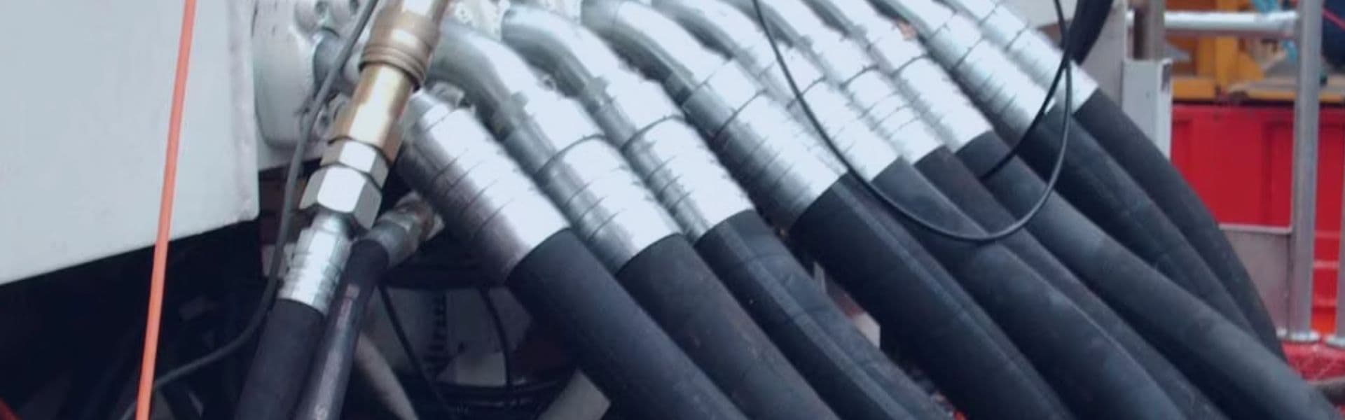
Hydraulic System Leaks: A Direct Result of Misaligned Valves

Detecting Leaks Early to Avoid Catastrophic Failures

Hydraulic system leaks caused by misaligned ball valves are among the most damaging issues a system can face. These leaks often start small but can quickly grow into catastrophic failures if left unaddressed. Misalignment places uneven pressure on valve seals, leading to cracks or gaps that allow fluid to escape. This not only wastes valuable resources but can also compromise system efficiency and safety.

Early detection is critical in preventing these problems. Operators should routinely inspect the system for visible signs of leaks, such as pooling fluid, damp areas around valves, or reduced fluid levels in reservoirs. Additionally, monitoring system performance metrics like pressure drops or unusual pump behavior can provide clues about hidden leaks. For instance, if a pump is working harder than usual to maintain pressure, it could indicate fluid loss somewhere in the system. Using advanced tools like ultrasonic leak detectors or thermal imaging cameras can help pinpoint leaks before they escalate, saving time, money, and equipment.

Key Areas to Inspect for Leaks Around Ball Valves

When checking for leaks caused by valve misalignment, certain areas deserve special attention. The valve seals and seats are the most common weak points. Misaligned valves exert uneven force on these components, causing them to degrade over time. Look for signs of wear, cracks, or fluid buildup around these areas.

The valve stem is another critical point to inspect. Misalignment can cause the stem to shift or warp, creating gaps where fluid can escape. Regularly checking the stem for proper alignment and ensuring it moves freely can prevent minor issues from turning into major leaks.

Additionally, inspect the connection points where the valve integrates with the pipeline. Loose fittings or improperly aligned connections can result in leaks, especially under high pressure. Tightening these connections and verifying alignment during routine maintenance can help maintain a leak-free system.

The Impact of Ball Valve Off Position on System Longevity

Accelerated Corrosion and Metal Fatigue Risks

A ball valve in an off position can dramatically shorten the lifespan of a fluid system by increasing the risk of corrosion and metal fatigue. Misalignment often creates areas of turbulence within the pipeline, where the fluid flow becomes uneven. This turbulence can lead to localized erosion, exposing the valve and surrounding components to accelerated wear. Over time, this creates weak spots in the valve’s structure, making it more susceptible to cracking and eventual failure.

Additionally, misalignment can trap moisture and debris within the valve housing, fostering conditions conducive to corrosion. This is especially problematic in systems that handle corrosive fluids or operate in humid environments. Corrosion weakens the valve’s metal components, compromising their integrity and leading to leaks or complete valve failure. Regular inspections and prompt corrections of misalignment are essential to prevent these risks and maintain the structural health of the valve and pipeline.

How Misaligned Valves Affect Seal Durability

Valve seals are designed to maintain a tight, leak-proof connection, but misalignment places uneven stress on these critical components. When a valve is off position, the seal’s contact points may become distorted, reducing its ability to hold pressure effectively. This distortion causes gradual wear and, in some cases, can lead to the seal cracking or tearing under the strain.

As seals degrade, leaks become inevitable, leading to fluid loss, system inefficiencies, and potential safety hazards. Moreover, compromised seals often allow contaminants to enter the system, which can further accelerate wear and tear on other components. The cumulative effect of misalignment and seal failure significantly shortens the overall lifespan of the valve and the system it serves.

Ensuring proper alignment during installation and conducting regular maintenance checks on the valve and its seals can mitigate these risks. Replacing worn seals promptly and addressing alignment issues as soon as they arise are cost-effective measures that protect both the valve and the system’s longevity. By prioritizing these steps, operators can maintain a durable, efficient system and avoid costly repairs or replacements down the line.

Troubleshooting Valve Actuator Issues

Identifying Actuator Problems Affecting Valve Position

Valve actuators are critical for controlling the position of ball valves, ensuring proper flow regulation and system efficiency. However, when actuators malfunction, they can cause the valve to be misaligned or stuck in an off position. Common issues include electrical faults in motorized actuators, insufficient pneumatic or hydraulic pressure in powered actuators, or mechanical wear in manual actuator components.

Signs of actuator problems often manifest as inconsistent valve movement, delays in operation, or the inability to achieve a fully open or closed position. Operators may also notice irregular system behavior, such as pressure drops or erratic flow rates. Using diagnostic tools, such as a multimeter for electrical actuators or pressure gauges for pneumatic systems, can help pinpoint the root cause of the issue. Routine visual inspections for loose connections, damaged components, or fluid leaks around actuators are also essential for early detection.

Signs Your Ball Valve Off Position

Simple Fixes for Common Actuator Failures

Addressing actuator problems doesn’t always require extensive repairs or replacements. Some common issues can be resolved with straightforward fixes. For example:

Electrical Actuators: If an actuator fails to respond, check the power supply and connections for faults. Loose wiring or blown fuses are often to blame. Restoring proper electrical connections or replacing faulty components can quickly resolve the issue.

Pneumatic or Hydraulic Actuators: A pressure drop often indicates a leak or blockage in the system. Inspect hoses, fittings, and seals for damage and replace them as needed. Additionally, verify that the pressure regulator is set to the correct level for optimal actuator performance.

Manual Actuators: Stiff or unresponsive manual actuators may simply require lubrication to restore smooth movement. In cases of excessive wear or stripped gears, replacing worn components can bring the actuator back to working condition.

After making repairs, always recalibrate the actuator to ensure it moves the valve into the correct position. Testing the system under normal operating conditions will confirm whether the issue has been fully resolved. For more complex problems, consulting the actuator’s manual or seeking assistance from a technician may be necessary to prevent further complications.

When to Replace Your Ball Valve

Recognizing the Signs of a Failing Valve

Ball valves are designed for durability, but they won’t last forever. Over time, wear, corrosion, and mechanical stress can compromise their functionality. Recognizing the signs of a failing valve early can prevent costly system failures and downtime.

Common indicators include persistent leaks around the valve, even after tightening or replacing seals. Difficulty in turning the valve handle, which may indicate internal blockages or corroded components, is another red flag. Inconsistent flow rates, pressure fluctuations, or the inability to fully open or close the valve suggest internal damage, such as a deformed ball or compromised seats. Unusual noises, such as hissing or whistling, may also signal that the valve is no longer maintaining a proper seal.

Frequent repairs on the same valve are another warning sign. If maintenance costs are mounting and performance remains subpar, it’s often more cost-effective to replace the valve than to continue with patchwork fixes.

Choosing the Right Replacement: Material and Size Considerations

Selecting the right replacement ball valve is critical to maintaining system performance and longevity. The choice depends on several factors, including the fluid or gas being transported, system pressure, and operating conditions.

Material: The valve’s material must be compatible with the fluid and environmental conditions. Stainless steel is ideal for corrosive or high-temperature applications, while brass is suitable for water and mild chemicals. Plastic valves, such as those made from PVC or CPVC, are lightweight and corrosion-resistant, making them perfect for low-pressure or non-aggressive fluid systems.

Size: The replacement valve must match the dimensions of the existing pipeline. Check the valve’s diameter and connection type to ensure a proper fit. Using the wrong size can lead to flow restrictions or leaks, negating the benefits of a new valve.

Special Features: Consider whether your system requires additional features, such as locking mechanisms for safety, a three-way design for directional control, or anti-static components for flammable fluids.

Certifications: Verify that the replacement valve meets relevant industry standards, such as ISO or ANSI certifications, to ensure quality and compatibility with your system.

Steps to Prevent Ball Valve Position Issues

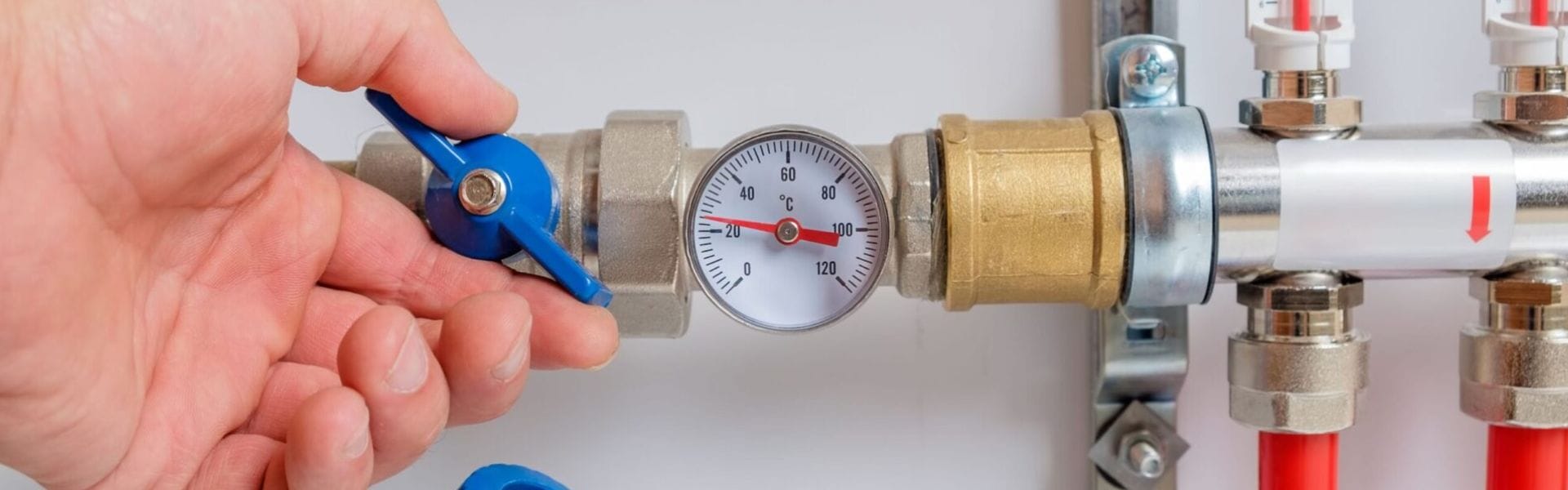
Routine Valve Inspections and Predictive Maintenance

Preventing ball valve position issues begins with a proactive approach to maintenance. Regular inspections are critical to identifying potential problems before they escalate. During these inspections, operators should:

Check for Visible Signs of Wear and Damage: Look for corrosion, leaks, or deformation around the valve and its components.

Test Valve Movement: Open and close the valve to ensure smooth operation. Resistance or stiffness may indicate internal buildup or misalignment.

Monitor System Performance: Keep an eye on pressure readings and flow rates. Sudden drops could signal valve misalignment or wear.

Predictive maintenance adds another layer of protection. By using advanced tools like vibration analysis, thermal imaging, or ultrasonic sensors, operators can detect hidden issues such as internal wear or leaks. Creating a maintenance schedule that includes these regular checks ensures the valve remains in proper working condition, reducing the likelihood of sudden failures or costly repairs.

Tips for Ensuring Proper Installation and Alignment

Proper installation is the foundation of a well-functioning ball valve. Missteps during setup often lead to misalignment and operational issues. To avoid this, follow these best practices:

Prepare the Installation Site: Ensure the pipeline is clean and free of debris before installing the valve. Dirt or particles can interfere with alignment and cause damage during operation.

Verify Correct Orientation: Install the valve in the correct flow direction, as indicated by the manufacturer’s markings. Improper orientation can compromise performance and shorten the valve’s lifespan.

Secure Connections Properly: Tighten all fittings and connections to prevent leaks. Use appropriate tools and avoid over-tightening, which can deform the valve or its seals.

Check Alignment After Installation: Use valve position indicators or alignment tools to ensure the valve is properly seated. Misalignment during installation can lead to uneven wear and inefficient operation.

Test Before Operation: Open and close the valve several times after installation to verify smooth movement and proper alignment. This step helps confirm that the valve is ready for use.

Conclusion

Misaligned ball valves can lead to leaks, flow disruptions, energy waste, and long-term damage to your system. Early detection of warning signs—such as pressure drops, reduced flow, or visible leaks quality components, is key to system reliability. At Topa, we offer premium ball valves designed for durability and precision, ensuring your system runs smoothly. Don’t risk costly downtime—upgrade to Topa ball valves today for optimal performance and peace of mind.


FAQ

What are the common signs of a misaligned ball valve?

Common signs include leaks around the valve, pressure drops, reduced flow rates, difficulty operating the valve, and unusual system noises such as whistling or hammering.

How often should ball valves be inspected?

Routine inspections should be conducted every six months, but high-use or critical systems may require more frequent checks.

What causes ball valve misalignment?

Misalignment can be caused by improper installation, wear and tear, external vibrations, or incorrect handling during maintenance.

Can a misaligned valve damage the system?

Yes, misaligned valves can lead to increased energy consumption, leaks, system inefficiencies, and accelerated wear on other components, potentially causing significant damage.

How can I prevent ball valve alignment issues?

Prevent issues by following proper installation practices, conducting regular inspections, using alignment tools, and scheduling predictive maintenance.

When should I replace a ball valve?

Replace the valve when you notice persistent leaks, difficulty in operation, visible corrosion, or recurring issues despite repairs.

Unlocking the Ball Valve Open Position banner

Unlocking the Ball Valve Open Position: Tips You Need to Know

Knowing the open position of a ball valve is essential for ensuring the smooth and efficient operation of fluid or gas systems. A misidentified valve position can lead to reduced flow efficiency, leaks, or even safety hazards in high-pressure applications. Whether you’re managing a residential plumbing setup or an industrial system, understanding how to spot the ball valve’s open position helps you maintain control, prevent costly errors, and optimize performance.

Ball Valve Basics

What is a Ball Valve? Key Features and Functionality

A ball valve is a mechanical device designed to control the flow of liquids or gases through a pipeline. Its core mechanism revolves around a spherical ball with a hole (or bore) through its center. When the hole aligns with the pipeline, the valve is open, allowing unrestricted flow. A 90-degree rotation of the ball, controlled by a handle or actuator, shifts the hole out of alignment, completely blocking the flow.

Ball valves are widely regarded for their reliability, ease of operation, and versatility. They provide a tight seal when closed, which minimizes leaks even under high-pressure conditions. Key features include:

Quick Operation: The quarter-turn mechanism makes them easy to use.

Low Pressure Drop: The unobstructed flow path ensures minimal resistance.

Durability: Materials like stainless steel, brass, or PVC resist corrosion and wear, making ball valves suitable for long-term use.

From residential plumbing to industrial pipelines, ball valves are crucial for managing flow efficiently and safely.

Anatomy of a Ball Valve: Breaking Down the Components

To understand how a ball valve works, it’s important to know its main components:

Valve Body: The outer casing that houses all other parts, designed to withstand pressure and environmental conditions.

Ball: The central spherical component with a drilled hole that regulates flow. Its precise design ensures smooth operation and a tight seal.

Handle: The external part that allows manual control of the valve. By turning the handle, users rotate the ball inside.

Stem: The rod that connects the handle to the ball, transmitting motion.

Seats: Ring-shaped components that cradle the ball and form a seal to prevent leaks.

Seals and Gaskets: Ensure tight connections between the body and other components to maintain pressure integrity.

Each part works together to create a robust, user-friendly mechanism capable of handling a wide range of applications.

Ball Valve components

Ball Valve Orientation: How Position Impacts Flow

The orientation of the ball inside the valve dictates whether the flow is open, restricted, or completely blocked:

Open Position: When the ball’s hole aligns with the pipeline, the flow moves freely with little resistance. The handle is parallel to the pipeline, making the open position easy to spot.

Closed Position: A 90-degree turn rotates the solid side of the ball into the flow path, stopping fluid or gas movement entirely. In this state, the handle is perpendicular to the pipeline.

Intermediate Position: In some applications, the valve may be partially open to regulate flow. This position is less common due to potential wear on the seats.

Orientation is critical for ensuring proper system operation. Misalignment or misunderstanding of the valve’s position can lead to reduced efficiency, leakage, or system damage. Properly identifying and maintaining alignment ensures the valve functions optimally in any setting.

Identifying the Ball Valve Open Position

Handle Position: The Simplest Indicator of Valve Status

One of the most straightforward ways to determine whether a ball valve is open is by observing the handle position. Most ball valves are designed so that the handle directly indicates the valve’s status:

Open Position: The handle is aligned parallel to the pipeline. This indicates that the ball’s internal hole is in line with the flow, allowing fluids or gases to pass through freely.

Closed Position: The handle is perpendicular to the pipeline. This signals that the solid part of the ball is blocking the flow entirely.

This design makes ball valves intuitive to operate, but it’s not always foolproof. In some cases, wear and tear or installation errors can cause the handle to misalign with the valve’s true position. In such instances, other indicators must be used to confirm the status.

Decoding Flow Direction with Visual Cues

Beyond the handle, visual cues on the valve body can provide additional clarity about the flow direction and status. Manufacturers often incorporate specific features to help users identify the valve’s open position accurately:

Arrows or Directional Markings:

Many valves feature arrows on the valve body, pointing in the direction of flow. If the arrow aligns with the pipeline, the valve is likely to open.

Bidirectional valves may not have arrows, so other methods like handle alignment are necessary.

Engraved Labels:

Terms like “OPEN” and “CLOSE” are sometimes engraved near the handle or on the valve body. These serve as a clear guide when determining the position, especially in poorly lit environments.

Color Codes:

Some ball valves have color-coded elements, such as green for opening and red for closing. These are particularly useful in large systems with multiple valves, allowing operators to identify statuses at a glance.

By using these visual cues alongside the handle position, users can double-check the valve’s state and minimize errors in operation.

Using Status Indicators for Confirmation

For an added layer of certainty, many modern ball valves come equipped with status indicators. These features are especially useful in complex systems where quick and accurate identification of valve positions is essential:

Mechanical Position Markers:

Some valves have built-in markers on the stem or handle that indicate the ball’s rotation. These markers are often in the form of raised notches or engraved symbols.

A visible “O” or “C” may correspond to the open or closed position, ensuring clear communication of the valve’s state.

Visual Windows:

Certain ball valves feature small windows that display the internal ball’s orientation. When the hole inside the ball is visible through the window, it confirms the valve is open.

Digital Indicators:

In advanced setups, digital monitoring systems can provide real-time feedback on the valve’s status. Sensors attached to the valve relay information to a control panel, enabling operators to confirm the position remotely.

Spring-Loaded Position Indicators:

Some valves incorporate spring-loaded mechanisms that visibly pop up or retract based on the valve’s position. This feature is often found in high-pressure or industrial applications where precision is critical.

Practical Steps to Identify the Open Position

To ensure accuracy, combine multiple methods when checking a ball valve’s open position:

Start by observing the handle alignment with the pipeline. If it’s parallel, the valve is likely open.

Look for visual cues, such as arrows, labels, or color codes, on the valve body.

Confirm the status using built-in indicators, such as mechanical markers or visual windows.

For systems with critical operations, use flow testing to verify that fluids or gases are moving as expected through the valve.

Why Accurate Identification Matters

Correctly identifying the open position of a ball valve is crucial for ensuring system efficiency and safety. Misidentifying the position can lead to leaks, reduced performance, or even hazardous conditions in high-pressure or sensitive environments. For example:

In plumbing systems, leaving a valve partially closed can disrupt water pressure and cause damage to appliances.

In industrial settings, an incorrect valve position could lead to dangerous chemical leaks or pressure buildup.

Common Misconceptions About Ball Valve Operation

Myths About Handle Alignment: When It Can Be Deceptive

Handle alignment is often considered the gold standard for identifying a ball valve’s position, but it’s not always foolproof. Several misconceptions surround the reliability of the handle as an indicator:

Misalignment Due to Wear and Tear: Over time, the connection between the handle and the valve’s stem can loosen or degrade. This can result in the handle showing a parallel position to the pipeline, even when the valve is not fully open.

Installation Errors: During installation, improper tightening or positioning of the handle can cause it to misrepresent the actual valve position. For example, if the handle is attached slightly off-axis, it may look parallel when the valve is partially open.

Assuming All Handles Work the Same Way: Not all ball valves use the same handle design. Some may have custom configurations or designs that operate differently from standard parallel/perpendicular indicators. For instance, in certain compact systems, the handle might rotate in the opposite direction.

Blocked Internal Mechanism: Debris or internal obstructions can prevent the ball from fully opening or closing. Even if the handle indicates the valve is in the open position, the flow may still be restricted.

Key Takeaway:

While handle alignment is a valuable visual cue, always combine it with other methods—such as inspecting flow direction indicators or testing the valve function—to confirm the actual position. Relying solely on the handle can lead to operational errors, particularly in older or heavily used valves.

Ball Valve Open Position

Understanding Bidirectional vs. Unidirectional Flow in Ball Valves

Another common misunderstanding involves the directionality of ball valves and their impact on operation:

Bidirectional Valves:

Most ball valves are designed for bidirectional flow, meaning fluid or gas can travel in either direction when the valve is open. These valves are versatile and commonly used in residential and industrial systems.

The handle position or flow indicators are the primary methods for identifying whether the valve is open, as the direction of flow does not change the function.

Unidirectional Valves:

Some specialized ball valves allow flow in only one direction. These valves often have additional features, such as arrows or markings on the valve body, to indicate the correct flow path.

Attempting to reverse flow through a unidirectional valve can lead to damage, leaks, or inefficiencies.

Misinterpretation of Markings:

Operators often mistake the presence of directional arrows on bidirectional valves as a strict flow guide. In reality, these markings may be intended to aid installation or highlight the valve’s orientation, not limit its functionality.

Conversely, ignoring directional markings on unidirectional valves can lead to improper installation and system failures.

Application-Specific Misuse:

In high-pressure or chemical systems, using a bidirectional valve where a unidirectional valve is required can result in backflow issues or increased wear on internal components.

Key Takeaway:

Understanding whether your ball valve is bidirectional or unidirectional is critical for proper operation. Always verify the valve type, check for markings, and consult the manufacturer’s specifications to avoid misuse and potential damage.

Installation Insights for Ball Valves

Common Errors During Installation and How to Avoid Them

Improper installation of ball valves can lead to operational inefficiencies, leaks, and premature wear. Avoid these common mistakes to ensure smooth functionality:

Overtightening Connections:

Excessive force when tightening the valve can distort the body or damage the threads, leading to misalignment or leaks.

Solution: Use a torque wrench and adhere to manufacturer-recommended torque values.

Incorrect Valve Orientation:

Installing a unidirectional valve backward can block the flow and damage internal components.

Solution: Check for directional arrows or markings on the valve body before installation.

Skipping Thread Sealants:

Failure to use appropriate sealants, such as Teflon tape, can result in leaks at connection points.

Solution: Apply a suitable sealant evenly to the threads, avoiding excess that might contaminate the valve interior.

Improper Pipeline Preparation:

Connecting a valve to a pipeline with debris, burrs, or misaligned ends can cause operational problems.

Solution: Clean and inspect the pipeline ends, ensuring they align with the valve inlet and outlet.

Ignoring Material Compatibility:

Using a valve made of incompatible materials for the system media can lead to corrosion or deterioration.

Solution: Confirm the valve’s material is suitable for the fluid, pressure, and temperature conditions.

Ensuring Proper Valve Alignment During Setup

Correct alignment is essential to ensure the ball valve operates smoothly and reliably. Follow these steps to achieve proper setup:

Position the Valve Correctly:

Align the valve with the pipeline to ensure that the flow path is unobstructed. Misalignment can cause stress on the connections and hinder valve operation.

Level the Handle:

Ensure the handle is parallel to the ground or in a position that allows easy access and operation. Poor positioning can make the valve difficult to use or lead to misinterpretation of its status.

Center the Valve:

Check that the valve’s inlet and outlet ports are centered with the pipeline to avoid uneven stress that can damage the valve body or seats.

Secure the Valve Firmly:

Use appropriate clamps or supports to hold the valve in place, especially for larger or heavier valves. This prevents movement due to vibrations or pressure fluctuations.

Account for Expansion and Contraction:

In high-temperature systems, allow room for thermal expansion and contraction to avoid excessive stress on the valve and connections.

Testing the Valve Post-Installation to Verify Operation

Once the valve is installed, testing is crucial to confirm proper functionality and alignment. Here’s a step-by-step guide:

Perform a Visual Inspection:

Ensure all connections are tight and that the handle is properly aligned with the pipeline. Look for any visible defects or misalignment.

Conduct a Pressure Test:

Slowly introduce pressure to the system and observe the valve for leaks around the body and connections.

If the valve leaks, tighten connections or replace damaged seals as needed.

Cycle the Valve Through Its Positions:

Rotate the handle to open and close the valve fully. This ensures the ball moves freely and aligns correctly with the pipeline.

Listen for unusual sounds, such as grinding or squeaking, which could indicate internal obstructions or misalignment.

Check for Flow Integrity:

Open the valve fully and verify that fluid or gas flows without resistance. Close the valve and confirm that the flow is completely stopped.

Confirm Indicator Functionality:

If the valve has built-in indicators, such as markings or visual windows, verify that they correspond accurately to the valve’s position.

Document Results:

Record the testing results, including pressure levels and any adjustments made. This provides a reference for future maintenance.

Maintenance for Smooth Operation

Routine Inspections: What to Check and When

Routine inspections are essential for maintaining ball valves in optimal condition and ensuring their longevity. Regular checks can help identify and address minor issues before they escalate. Here’s what to look for during inspections:

Handle Movement:

Test the handle to ensure it rotates smoothly between the open and closed positions. Stiff or restricted movement could indicate internal obstructions or mechanical wear.

Alignment Accuracy:

Verify that the handle’s alignment with the pipeline corresponds to the valve’s actual position. Misalignment could signal wear in the stem or ball mechanism.

Visible Leaks:

Inspect the valve body, connections, and seals for any signs of leaks, such as moisture, drips, or residue buildup. Leaks often indicate damaged seals or loose fittings.

Valve Surface Condition:

Look for corrosion, rust, or surface damage, especially in valves exposed to harsh environments or corrosive fluids.

System Pressure and Flow:

Monitor the system for unusual pressure drops or flow inconsistencies that could signal a partially open valve or internal blockage.

Inspection Schedule:

Cleaning the Valve to Remove Debris and Build-Up

Over time, ball valves can accumulate debris, sediment, or mineral deposits, especially in systems with hard water or particulate-laden fluids. Cleaning the valve ensures smooth operation and prevents long-term damage.

Disassemble the Valve:

Shut off the system and relieve pressure before removing the valve. Carefully disassemble it to expose the internal ball, seats, and seals.

Remove Debris:

Use a soft, non-abrasive brush or cloth to clean the internal components, including the ball and seats. For stubborn build-up, soak the components in a cleaning solution recommended by the valve manufacturer.

Inspect Components:

Examine the ball for scratches or cracks and check the seals for wear or damage. Replace any compromised parts before reassembling the valve.

Flush the System:

After cleaning, flush the pipeline to remove any remaining debris that could reenter the valve.

Reassemble and Test:

Reassemble the valve carefully, ensuring all components are aligned correctly. Test the valve’s operation to confirm smooth movement and leak-free performance.

Pro Tip:

Schedule cleaning more frequently in systems with high contamination risks, such as industrial or untreated water lines.

Proper Lubrication for Longevity and Efficiency

Lubrication reduces friction between moving parts, ensuring smoother operation and minimizing wear. It is especially important for valves exposed to frequent use or extreme conditions.

Choose the Right Lubricant:

Use valve-specific lubricants compatible with the valve’s materials and the system’s fluid. Avoid using generic greases that may degrade seals or contaminate the system.

Apply Lubricant to Key Areas:

Focus on the stem, seats, and internal ball surface. A thin, even layer of lubricant ensures optimal movement without over-application.

Lubrication Frequency:

Lubricate during annual inspections or more frequently for high-use valves or those operating in harsh environments.

Monitor Lubricant Condition:

Check for signs of dried or degraded lubricant, which can hinder performance. Replace old lubricant with fresh applications as needed.

Benefits of Proper Lubrication:

Prevents sticking or jamming of the handle.

Reduces internal friction, extending the lifespan of components.

Protects against rust and corrosion in metallic valves.

Conclusion

By combining these practices, you can ensure optimal performance, minimize downtime, and extend the lifespan of your valves. Ready to elevate your system’s performance? Start implementing these tips today and experience the difference!


FAQ

How can I tell if a ball valve is open or closed?

If the handle is parallel to the pipeline, the valve is open. If it’s perpendicular, the valve is closed.

What do directional arrows on a ball valve mean?

Directional arrows indicate the flow direction for unidirectional valves or help confirm proper alignment for bidirectional valves.

Why is my ball valve handle hard to turn?

This may be due to corrosion, debris buildup, or a lack of lubrication. Regular maintenance can resolve and prevent this issue.

Can ball valves be used for throttling?

Ball valves are not ideal for throttling as it can cause wear on the ball and seats, reducing their lifespan.

How often should ball valves be inspected?

Ball valves should be inspected at least annually or more frequently in high-use or critical systems.

What materials are best for durable ball valves?

Stainless steel and brass are excellent choices for durability and resistance to corrosion in various applications.

Hydraulic Hose Mandrel banner

Hydraulic Hose Mandrel: A Critical Component for Performance

A hydraulic hose mandrel serves as the backbone of the hose production process. It is a cylindrical form around which the hose material is extruded and shaped, ensuring that the internal diameter of the hose is uniform and precise. The mandrel is integral in forming the hose’s structural integrity, maintaining its strength while allowing for flexibility.

What is a Hydraulic Hose Mandrel?

A hydraulic hose mandrel is a cylindrical form that serves as the foundation around which a hydraulic hose is formed during the manufacturing process. It acts as a mold or core around which the various layers of hose material — such as rubber, thermoplastic, or metal wire reinforcement — are applied. The primary function of the mandrel is to give the hose its internal shape and diameter while ensuring that it maintains the required structural integrity, flexibility, and performance characteristics once the hose is complete. The mandrel’s role is pivotal in ensuring that the hose meets the necessary specifications, including pressure resistance, bend radius, and overall durability for various industrial applications.

Hydraulic Hoses Mandrel

Types of Mandrels

There are two main types of hose mandrels, each serving a distinct purpose in hose production:

Solid Mandrels:

Solid mandrels are a solid, cylindrical piece typically made of steel or aluminum. They are used in the production of hoses that require greater internal pressure resistance and structural integrity. The solid mandrel is often used for hoses with thicker walls or those that need to handle high-pressure applications. The solid core helps ensure the hose retains its internal diameter as the layers of material are applied and the hose is cured, resulting in a durable and robust hose structure.

Hollow Mandrels:

Hollow mandrels, as the name suggests, have a hollow center and are commonly used in the production of hoses that require lighter weight or greater flexibility. These mandrels are ideal for creating hoses that need to bend more easily, such as flexible hydraulic hoses. The hollow design makes them more suited for hoses where the internal diameter must be kept consistent but the overall weight and flexibility of the hose are key considerations. Hollow mandrels are also used in situations where hoses are designed for low-pressure systems.

Basic Structure and Material

The structure and materials of a hose mandrel play a significant role in ensuring the hose is formed correctly and maintains its shape throughout the manufacturing process. Mandrels are generally cylindrical, smooth, and precisely shaped to meet the desired hose specifications.

Mandrel Material:

The materials used for mandrels are chosen based on their durability, corrosion resistance, and ability to withstand the heat and pressure during the hose extrusion process. Common materials include:

Steel: Steel mandrels are often used for their strength and durability. They are resistant to wear and tear and can withstand the high pressures involved in manufacturing high-performance hoses. Steel is a popular choice for solid mandrels.

Aluminum: Aluminum mandrels are lighter than steel and are typically used for hoses where weight is a critical factor. Aluminum is also resistant to corrosion, making it suitable for hoses exposed to harsh environments.

Rubber-Coated Mandrels: Some mandrels are coated with rubber to prevent damage to the hose during the manufacturing process. This rubber coating also helps to create a smooth internal surface for the finished hose, which can improve flow characteristics and reduce friction.

Mandrel’s Role in the Manufacturing Process

The mandrel is integral to the extrusion process of hydraulic hose production, ensuring that the hose takes the desired shape and size. Here’s how the mandrel functions in the manufacturing process:

Extrusion:

The hose material, typically a mixture of rubber or thermoplastic, is fed through an extruder, where it is heated and shaped around the mandrel. The mandrel provides the necessary form for the hose’s internal diameter, ensuring uniformity and consistency throughout the production process.

Layering:

As the hose material is extruded, multiple layers may be added, such as reinforcement layers made of steel wires or braided metal. These layers are designed to provide additional strength and pressure resistance to the hose. The mandrel holds the layers in place and helps to ensure that the hose maintains its shape and uniform thickness.

Curing:

Once the hose is formed around the mandrel, the entire assembly is moved to a curing oven where it is heated to the required temperature. This curing process solidifies the rubber or thermoplastic material, bonding the layers together and setting the hose’s final shape. The mandrel continues to play a role here by preventing the hose from deforming during the curing process.

Removal:

After curing, the hose is cooled, and the mandrel is removed. In some cases, the mandrel is removed immediately, while in other cases, it may be designed to stay inside the hose, serving as an inner layer. This depends on the specific requirements of the hose and its intended application.

The Importance of the Mandrel in Hydraulic Hose Production

Ensuring Consistent Quality

One of the primary functions of the hose mandrel is to ensure uniformity in wall thickness and maintain consistency in hose quality. When manufacturing hydraulic hoses, achieving a precise and uniform internal diameter is crucial. The mandrel acts as the internal form around which the hose is built, ensuring that the wall thickness is consistent throughout the length of the hose. This uniformity is important for several reasons:

Pressure Resistance: The uniform wall thickness is directly related to the pressure rating of the hose. If the wall thickness varies, it can lead to weak points where the hose is more likely to fail under pressure. The mandrel ensures that the hose has consistent pressure tolerance across its entire length.

Performance Consistency: In hydraulic systems, reliability is key. A hose with inconsistent wall thickness might perform poorly or even fail in the field, leading to downtime or accidents. The mandrel guarantees that each hose produced will meet stringent performance standards, especially in demanding, high-pressure applications.

Quality Control: By standardizing the shape and dimensions of the hose during production, the mandrel system serves as a critical tool for quality control. It ensures that each hose produced meets precise specifications, reducing the likelihood of defects and ensuring that the final product performs optimally in its intended application.

Impact on Flexibility and Durability

The design and material of the mandrel have a significant impact on the flexibility, pressure tolerance, and durability of the finished hydraulic hose. These factors are essential for the hose’s performance in dynamic, high-pressure environments.

Flexibility:

Hydraulic hoses are often required to flex and bend in various directions without kinking or losing their shape. The type of mandrel used during manufacturing — solid or hollow — influences the final hose’s flexibility. Hollow mandrels are typically used when flexibility is a top priority, as they help create hoses that are lightweight and easy to maneuver. The flexibility of the hose is essential in applications where it needs to move with machinery or equipment, such as in construction or agricultural settings.

Pressure Tolerance:

Hydraulic hoses are often used in systems that involve high-pressure fluid transfer. The mandrel plays a critical role in determining the pressure tolerance of the hose. By shaping the hose accurately and uniformly, the mandrel ensures that the hose can withstand the pressure forces without collapsing or rupturing. Solid mandrels, due to their structural integrity, are often used when creating hoses for high-pressure systems.

Durability:

The durability of a hydraulic hose is largely dictated by the materials and construction used during manufacturing. The mandrel helps maintain the structural integrity of the hose throughout the production process. For example, if a hose needs to withstand extreme weather conditions, abrasive materials, or high temperatures, the mandrel will ensure the hose is formed with the appropriate materials and structure to provide durability. Additionally, the rubber-coated mandrels prevent damage to the hose during the manufacturing process and ensure a smooth internal surface, which enhances the hose’s ability to withstand wear and tear over time.

Metal Hydraulic Hose Mandrel

Customization and Precision

The hose mandrel plays a vital role in the customization and precision required in many hydraulic applications. Often, hydraulic systems require hoses with unique dimensions, configurations, or performance characteristics that are tailored to a specific machine or operating environment.

Custom Sizes and Shapes: Hydraulic hoses may need to be produced in non-standard sizes or configurations. Mandrels are essential for ensuring these custom hoses are formed correctly and precisely, adhering to specific internal diameters and wall thicknesses. For instance, a mandrel might be used to produce hoses that need to fit into tight spaces or specific connectors. Custom mandrels can also be designed to produce hoses with non-circular cross-sections or complex internal profiles.

Specialized Applications: Some applications may require hoses that can operate in extreme conditions, such as high-pressure environments, fluctuating temperatures, or exposure to corrosive fluids. Mandrels can be customized to produce hoses with specific performance characteristics, such as enhanced flexibility, abrasion resistance, or chemical compatibility. For example, a high-temperature mandrel can help produce hoses that can withstand elevated temperatures, while abrasion-resistant mandrels can ensure that the hose can endure harsh environmental conditions.

Precision Manufacturing: Hydraulic hose production requires highly precise manufacturing to ensure the hose meets rigorous industry standards. The mandrel’s ability to maintain uniformity and accuracy in dimensions is crucial for ensuring precision in every hose produced. This precision is vital not only for performance but also for safety, as poorly made hoses can lead to leaks, ruptures, and system failures.

Common Issues with Hose Mandrels

Mandrel Wear and Tear

Like any component in hydraulic hose production, mandrels experience wear and tear over time, especially with frequent use in high-pressure environments. These stresses can lead to several issues that impact their performance and the quality of the hoses produced.

Surface Damage: Continuous contact with the hose material, high extrusion temperatures, and mechanical stress can cause abrasions or scratches on the mandrel’s surface. Over time, this damage can affect the smoothness of the hose’s interior, resulting in uneven internal diameters, which can negatively affect fluid flow.

Material Degradation: Frequent use in extreme conditions can degrade the mandrel material, especially for those made of aluminum or composite materials. This can reduce the mandrel’s strength and resilience, making it more susceptible to bending or breaking under pressure.

Loss of Structural Integrity: For solid mandrels, repetitive use can cause the material to fatigue, weakening its overall structural integrity. For hollow mandrels, pressure buildup during the hose manufacturing process may lead to deformation, making them less effective at creating the desired hose shape.

Inaccuracies in Hose Formation

If a mandrel is damaged or out of alignment, it can lead to significant inaccuracies in the hose formation, ultimately resulting in defective hoses. Common issues include:

Non-uniform Wall Thickness: If the mandrel is bent, scratched, or misaligned, it can cause variations in the hose’s wall thickness. This inconsistency can affect the pressure tolerance and durability of the hose, potentially causing it to fail under pressure.

Internal Deformities: If a mandrel has lost its shape or alignment, it may not support the hose evenly during production, leading to internal defects such as indentations or narrow sections within the hose. These defects can result in flow restriction, affecting the efficiency of the hydraulic system.

Poor Hose Flexibility: Inaccurate mandrel alignment or wear can also influence the hose’s flexibility. A damaged or improperly aligned mandrel can prevent the hose from being properly formed, leading to stiffness and reduced bending capacity. This can impact performance in systems that require hoses to flex or move regularly.

Cleaning and Maintenance

Regular cleaning and maintenance are essential for keeping mandrels in optimal working condition, ensuring consistent hose production quality, and preventing common issues like wear and inaccuracies. Here are some essential maintenance tips:

Regular Inspection: Mandrels should be routinely inspected for signs of damage, such as cracks, dents, or surface wear. Regular checks will help identify issues early before they impact hose production. The inspection should also assess alignment, ensuring that the mandrel is straight and level to avoid inaccuracies in hose formation.

Cleaning: Mandrels should be thoroughly cleaned after each use to remove any buildup of residue, such as rubber, grease, or debris. Solvents and soft brushes are commonly used for cleaning. For more stubborn residues, abrasive pads or cleaners can be used, but care should be taken to avoid damaging the mandrel’s surface.

Lubrication: Proper lubrication can reduce friction during the extrusion process, helping prevent abrasions and ensuring the mandrel remains smooth. A light coating of lubricant can be applied to the mandrel before each use.

Conclusion

Choosing the correct hose mandrel is not just about creating a durable and flexible hose; it’s also about enhancing the efficiency, safety, and cost-effectiveness of the entire hydraulic system. The right mandrel ensures that the hoses meet the specific demands of the application, providing the strength to handle pressure while maintaining flexibility and reliability over time. If you need suitable hydraulic hoses, just contact us!


FAQ

What is a hose mandrel?

A hose mandrel is a cylindrical form used in the manufacturing process of hydraulic hoses to shape the hose and maintain its internal diameter and structural integrity during production.

What are the different types of hose mandrels?

The three main types of hose mandrels are solid mandrels, hollow mandrels, and flexible mandrels. Each type serves a specific purpose, such as creating thicker, high-pressure hoses or flexible hoses for dynamic applications.

How does a mandrel affect hydraulic hose performance?

The mandrel plays a critical role in ensuring uniform wall thickness, strength, and flexibility, all of which are essential for the hose to perform well under pressure, resist wear, and maintain fluid flow.

What materials are hose mandrels made from?

Mandrels can be made from various materials, including steel, aluminum, rubber-coated materials, and composites. The choice of material depends on the desired hose properties such as weight, strength, and corrosion resistance.

How do I maintain a hose mandrel?

To maintain a mandrel, regularly inspect it for damage, clean it after each use, lubricate it to reduce friction, and store it properly to avoid wear and corrosion.

What happens if the mandrel is damaged during production?

If the mandrel is damaged, it can lead to inaccuracies in hose formation, such as uneven wall thickness, internal defects, or reduced flexibility, which can compromise the hose’s performance and safety in hydraulic systems.

Contact Topa

Save 30% on maintenance costs with our easy-install hydraulic fittings. Contact Now!