Needle Valve vs Ball Valve banner

Needle Valve vs Ball Valve: Key Differences in Flow Control

While ball valves are known for their ability to provide rapid on/off flow control with a simple quarter-turn, needle valves are designed for precision flow regulation, allowing fine adjustments in low-flow applications.

Understanding Needle Valves

Definition

A needle valve is a type of valve used for precise control over fluid flow. Named for its slender, needle-like plunger, it allows for fine adjustments, which is essential in applications where accurate flow control is crucial. The design enables the valve to regulate flow with exceptional precision, especially in low-flow scenarios, making it ideal for tasks like sampling, calibration, and gradual pressure reduction.

Components

Needle valves consist of several key components that work together to control fluid flow finely:

Needle: The main control element, is tapered to fit into the valve seat, allowing fluid to flow around it in adjustable amounts. The needle’s sharp, pointed end allows for precise flow modulation.

Seat: The needle’s tapered tip sits into this seat, forming a tight seal when closed, preventing leakage. The seat is often made from materials that are compatible with the fluid being handled, enhancing durability.

Stem: The stem connects the needle to the handle or actuator, transmitting motion from the handle to the needle for control.

Body: The body houses the other components and provides the structure. Typically, needle valve bodies are made of durable materials like stainless steel, brass, or plastic, depending on the intended environment.
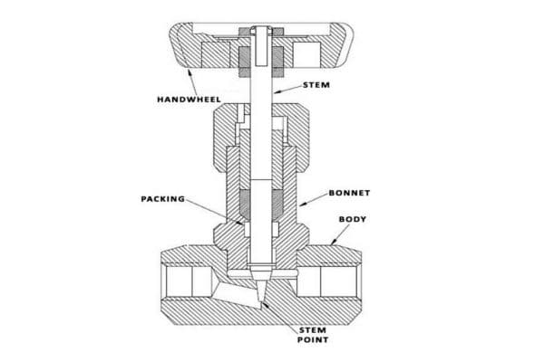
Needle Valve component

How It Works

Needle valves operate through a simple yet effective flow control mechanism. When the handle is turned, it rotates the stem, which raises or lowers the needle inside the valve body. The more the needle is lifted from the seat, the more fluid can pass around it, gradually increasing the flow. This threaded design enables fine adjustments, allowing operators to set the valve to the exact flow rate needed. As the needle moves closer to the seat, the flow rate decreases until the valve is completely shut off. This gradual control makes needle valves ideal for processes where small flow changes are necessary over time.

Advantages

Needle valves are highly valued for their ability to provide precise flow control. Unlike ball valves, which open and close quickly, needle valves are suited for applications where gradual flow modulation is critical. They are also well-equipped to handle high-pressure systems due to their robust construction, often withstanding pressures of up to several thousand psi. Their fine control allows for smooth, incremental adjustments, making them indispensable in sensitive applications where even minor fluctuations in flow or pressure can impact outcomes. Additionally, needle valves can achieve a tight shutoff, minimizing leakage, which is beneficial in applications involving hazardous or expensive fluids.

Applications

Due to their fine control capabilities, needle valves are common in a range of industries and applications where precise flow regulation is essential:

Laboratories: Needle valves are frequently used in lab settings for processes like sampling, testing, and calibration, where accurate flow rates are vital for experiments.

Pressure Regulation: In high-pressure systems, needle valves provide incremental adjustments to maintain stable pressures, ensuring equipment safety and performance.

Instrumentation: Needle valves are widely used in instrumentation setups, such as flow meters and pressure gauges, to ensure consistent and controlled flow for accurate readings.

Hydraulics and Pneumatics: These valves are utilized to control hydraulic fluid or compressed air in systems where slight changes in pressure or flow need to be finely managed.

Chemical Processing: Needle valves are often employed in the chemical industry for dosing and precise addition of chemicals into a process line, where control over flow is crucial to avoid reactions or contamination.

Needle Valves vs Ball Valves  

When choosing between needle valves and ball valves, it’s important to consider the specific needs of your system, such as flow control, pressure handling, and the level of precision required. While both are widely used for regulating the flow of fluids, their designs and functionalities are quite different. Below, we compare needle valves and ball valves across several critical parameters:

Flow Control Mechanism

Needle Valves:

Needle valves are specifically designed for fine, precise flow control. This precision is achieved through the tapered design of the needle, which fits into the valve seat. As the valve stem is rotated, the needle gradually moves into or out of the seat, regulating the flow rate incrementally. This allows operators to adjust the flow in very small amounts, making needle valves ideal for applications where detailed control is critical. The thread design of the needle allows for fine adjustments, making them perfect for controlling flow in systems where the flow rate must be monitored and carefully regulated.

The main strength of needle valves lies in their ability to control low-flow applications with high accuracy, such as in laboratory settings or in applications where very specific fluid volumes need to be controlled. This ability to fine-tune the flow makes needle valves unsuitable for applications requiring high flow rates, as they are designed for slow, controlled changes in flow.

Ball Valves:

In contrast, ball valves operate on a much simpler mechanism. The valve uses a hollow, perforated ball that rotates inside the valve body. When the ball’s hole is aligned with the pipeline, the valve is fully open, allowing fluid to flow freely. When the ball is rotated 90 degrees, the hole is no longer aligned with the flow path, and the valve shuts off the flow. This quarter-turn operation is fast and provides on/off control with a low operating effort.

Ball valves excel in applications that require rapid shut-off or full-flow regulation. Their operation is simple, which makes them ideal for high-flow systems or situations where quick flow shutoff or isolation is needed. However, ball valves are not well-suited for fine flow modulation. They typically perform best when the valve is either fully open or fully closed, and any in-between states can be difficult to manage without specialized designs, such as V-port ball valves.
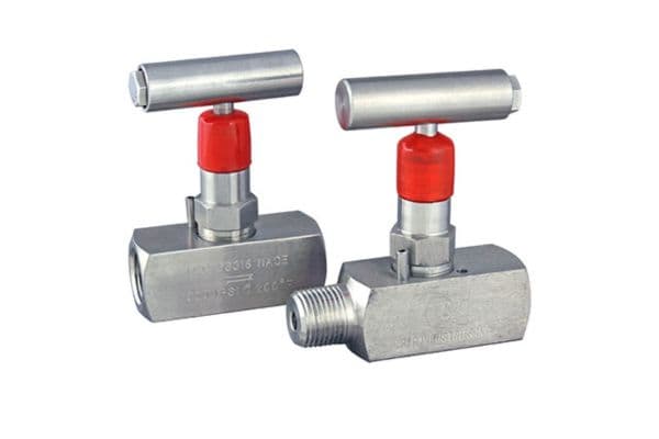
Needle Valves

Flow Rate and Pressure Handling

Needle Valves:

Needle valves are designed to handle low flow rates and high-pressure situations. Their precision threading allows them to regulate fluid in systems that require tight control under high-pressure conditions, without introducing significant pressure drops. The fine adjustment mechanism is particularly useful in environments where the fluid flow must be reduced gradually or held steady under variable pressure conditions. However, needle valves tend to have a higher resistance to flow compared to ball valves, which limits their use in high-flow systems.

In terms of pressure handling, needle valves are particularly suited for situations where precise regulation is needed, even at high pressure. This is because their sealing mechanism is designed to withstand significant pressure without leaking. Therefore, needle valves are commonly used in applications like pressure reduction, flow metering, and hydraulic systems where managing flow precisely is critical to the safety and efficiency of the process.

Ball Valves:

Ball valves, on the other hand, are designed for high flow and low pressure drop systems. The design of the ball valve allows fluid to pass through with minimal resistance, making them ideal for applications involving larger flow rates. Because of their quick opening and closing action, ball valves are able to handle fluids in large pipelines or systems that require rapid shutoff, such as in gas distribution or water treatment systems.

When it comes to pressure handling, ball valves generally perform well under moderate to high pressure, but they are more suitable for applications where the flow rates are high and there is not as much need for fine control. Unlike needle valves, ball valves are better for systems that require less regulation of flow and more control over overall flow rate and system isolation.

Precision and Adjustability

Needle Valves:

Needle valves shine when it comes to precision and adjustability. Their design allows for incremental adjustments, giving operators the ability to make very small changes in flow rates. This level of precision is especially useful in applications where consistent, gradual flow is important. Needle valves are commonly used in pressure regulation and metering applications, where the ability to finely control flow can make a significant difference in the system’s performance.

The threaded needle design offers high control over flow, but it also means the operation of the valve is relatively slow, requiring more turns of the handle or actuator to make even minor adjustments. This makes them unsuitable for applications that require fast, frequent changes in flow rate. In systems that demand fine control over flow rate, needle valves are often preferred over other valve types, but their limitations in terms of speed and maximum flow capacity must be considered.

Ball Valves:

Ball valves are less suited for fine adjustments compared to needle valves. While ball valves do provide fast, on/off control, their design doesn’t support the same level of precise, incremental adjustments that needle valves do. Ball valves work best in applications where the primary need is for either full-on or full-off flow regulation, and they are typically used in systems where the flow rate is either fully open or fully closed, such as in pipeline isolation, shutoff valves, or diverting flow.

However, in certain cases, ball valves can be designed with specialized ports (like V-port ball valves) or actuators to achieve a degree of flow modulation, but even then, they can’t match the precision offered by needle valves. Ball valves are ideal for situations where the flow must either be completely allowed or completely stopped, and they are not intended for gradual changes.

Choosing the Right Valve: Needle Valve vs Ball Valve

Application Suitability

When to Choose a Needle Valve

Needle valves are best suited for high-precision control applications where fine adjustments to the flow rate are critical. Their primary advantage lies in their ability to provide incremental flow regulation, which is essential in sensitive systems that require controlled flow under specific conditions. Common applications for needle valves include:

Laboratory Settings: Needle valves are frequently used in research and laboratory environments where precise fluid flow is necessary for experiments, calibration, or testing. In these settings, even small fluctuations in flow can lead to incorrect results, so needle valves are ideal for providing the fine control needed to maintain accuracy.

Instrumentation: For processes requiring precise measurement of flow rates, needle valves are preferred. They are often used in conjunction with flow meters, pressure gauges, or other measurement devices, where precise flow control ensures accurate readings.

Pressure Regulation: In systems where pressure must be carefully controlled, such as in hydraulic or pneumatic systems, needle valves are commonly employed. They allow for gradual pressure adjustments, making them suitable for applications where a stable, controlled pressure is necessary over time.

Needle valves are generally used in applications with low to medium flow rates and high pressure, where the ability to make small, controlled changes in flow is more important than achieving a high flow rate.
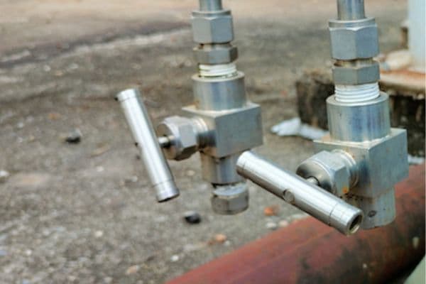
Needle Valve application

When to Choose a Ball Valve

Ball valves, on the other hand, are designed for on/off flow control and are typically used in systems where a quick shutoff or isolation is needed. The simplicity of the ball valve’s quarter-turn operation makes it suitable for applications where speed and reliability are paramount. Common use cases for ball valves include:

Industrial Pipelines: Ball valves are widely used in industrial pipelines where the main requirement is to control large volumes of fluid. They are often used for isolation purposes, such as turning on or off the flow of water, gas, or other materials through large-diameter pipes.

HVAC Systems: In heating, ventilation, and air conditioning (HVAC) systems, ball valves are used to control the flow of air or water with minimal pressure drop. They are also employed to isolate sections of the system during maintenance or when balancing the system.

Gas and Chemical Handling: Ball valves are ideal for systems where the flow of gases or chemicals needs to be stopped or started quickly. They are often used in shutoff applications, such as in gas distribution systems or in the oil and gas industry.

Ball valves excel in environments that require rapid flow control, such as systems with high flow rates and frequent shutoff demands. Their ability to handle large volumes of fluid with minimal resistance makes them unsuitable for applications that require fine, precise adjustments.

Flow Control Needs

Needle Valves for Precise Flow Regulation

Needle valves are specifically designed for highly controlled, low-flow applications. The key feature that sets them apart from other valve types is their ability to offer very fine adjustments to the flow. This is achieved through the threaded needle design, which allows the operator to make incremental changes in the flow rate. As the needle is adjusted, the opening through which the fluid flows becomes narrower or wider, offering precise control.

Needle valves are commonly used in applications where gradual changes in flow are necessary, such as in laboratories, calibration setups, or instrumentation systems. They are also used to restrict flow in pressure control systems to ensure that the pressure stays within safe and optimal ranges.

Ball Valves for Rapid Flow Control and Isolation

Ball valves, due to their simple quarter-turn operation, are designed for rapid flow control and complete shutoff. Once the valve is opened, it allows fluid to flow unrestricted until it is turned off, at which point the flow stops completely. This makes them ideal for applications requiring quick, full-flow isolation. Ball valves are often used in systems where the flow needs to be either fully on or fully off, with little to no intermediate control.

In large industrial processes or piping systems, ball valves offer a quick response time and minimal flow resistance, making them the ideal choice for high-flow applications like water treatment plants, HVAC systems, or natural gas pipelines. While they cannot match needle valves for precision, they are well-suited for systems where the need for precise flow regulation is secondary to rapid on/off control.

Pressure and Temperature Considerations

Pressure Handling

Needle valves are typically used in high-pressure applications where flow must be controlled precisely. Their design allows for high resistance to pressure fluctuations, and they can handle pressures of several thousand psi in certain configurations. This makes them ideal for hydraulic systems, gas sampling, or fluid systems that operate under high pressure, where controlling the pressure and flow rate is crucial for maintaining the integrity of the system.

While ball valves can handle moderate to high pressures, they are generally not suited for the same extreme pressure control that needle valves can provide. Ball valves can withstand pressures up to a certain point, but their primary function is to allow for full-flow control, which can result in increased pressure drops when used in high-pressure systems.

Temperature Tolerance

Both needle valves and ball valves can be designed to handle a wide range of temperatures, depending on the materials used in their construction. However, needle valves are often chosen for more temperature-sensitive applications due to their ability to provide fine flow regulation at a wide range of temperatures. High-quality needle valves can be constructed with materials that resist temperature fluctuations, ensuring stable performance.

Ball valves are typically better suited for higher temperature ranges and general industrial use, but they are usually employed in systems where temperature control is less of a concern. They can handle hot fluids or gases as long as the flow is either fully open or fully shut, which is ideal for applications where temperature regulation is less complex.

Conclusion

When choosing between a needle valve and a ball valve, it is essential to first consider the nature of the flow (high or low), the required precision, and the pressure and temperature conditions of the system. Needle valves are the go-to choice when fine control and precision are needed, while ball valves are the best option for systems requiring quick and reliable flow shutoff. Always align the valve selection with the system’s operational needs to ensure optimal performance and longevity.


FAQ

What is the main difference between a needle valve and a ball valve?

Needle valves offer precise flow control with fine adjustments, while ball valves provide quick, full-flow shutoff or isolation with a simple quarter-turn mechanism.

Which valve is better for high-pressure systems?

Needle valves are typically better suited for high-pressure systems where fine flow regulation is necessary.

Can ball valves be used for flow regulation?

While ball valves are great for on/off control, they are not suitable for precise flow regulation like needle valves. They are ideal for systems with high flow rates.

Where are needle valves typically used?

Needle valves are commonly used in laboratories, instrumentation systems, and pressure regulation applications where precision is critical.

Are ball valves good for industrial pipelines?

Yes, ball valves are commonly used in industrial pipelines, providing fast and reliable isolation with minimal pressure drop.

Can needle valves handle high flow rates?

Needle valves are generally designed for low-flow applications. For high-flow needs, ball valves are the better choice due to their ability to manage larger volumes.

Soft vs Rigid Core banner

Soft vs Rigid Core: Which is Right for Your Hydraulic Hose?

Core selection is not just a technical detail but a critical factor influencing the overall efficiency, longevity, and reliability of hydraulic systems. The right core can enhance the lifespan of a hose, reduce maintenance costs, and improve performance in high-pressure or high-flexibility applications.

Understanding Hydraulic Hoses and Their Core Components  

Hydraulic Hose Basics

A hydraulic hose is a critical component in hydraulic systems, designed to convey pressurized fluid between various parts of the system, such as pumps, valves, actuators, and cylinders. Hydraulic hoses are used in numerous industries, including construction, automotive, agriculture, and manufacturing, where high-pressure fluid power is needed to operate machinery and equipment. The primary function of a hydraulic hose is to transfer hydraulic fluid under high pressure, and this fluid can be oil, water, or other liquids depending on the application.

What makes hydraulic hoses indispensable is their ability to carry fluid at very high pressures, typically ranging from 1,000 to 5,000 psi, depending on the application. The key to maintaining such high pressures without leakage or failure is the design and construction of the hose, specifically the core and the layers surrounding it. The core material of a hydraulic hose plays a significant role in determining its pressure tolerance, flexibility, durability, and overall lifespan.

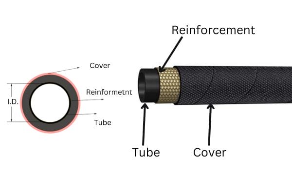
Hydraulic hose components design Topa

Core Structure in Hydraulic Hoses

The core of a hydraulic hose is the central component that directly interacts with the fluid being transferred. It serves as the primary structural element that withstands the pressure and maintains the internal flow of fluid. The core is typically made from materials that can handle internal pressure while resisting wear and tear over time.

In addition to pressure tolerance, the core of a hydraulic hose must also be flexible enough to allow for the hose’s movement without breaking or kinking. This balance between strength and flexibility is one of the key considerations in designing hydraulic hoses. The core works in conjunction with additional layers, such as reinforcement (made from steel or synthetic fibers) and outer covers (designed for abrasion resistance and environmental protection).

The core also plays a crucial role in determining the hose’s ability to handle high and low temperatures, as well as its chemical resistance. If the core material is too rigid, the hose may be unable to flex or bend without cracking, which could lead to failure. Conversely, if the core is too soft, the hose may not be able to withstand the pressure of the fluid, resulting in leakage or bursting.

Types of Core Materials

There are two primary types of core materials used in hydraulic hoses: softcore and rigid core. Each material offers distinct advantages and is selected based on the specific demands of the hydraulic system.

Soft Core:

Soft core materials are typically made from synthetic rubber or thermoplastic elastomers (TPE). These materials are flexible, lightweight, and resistant to kinking, making them ideal for applications where the hose needs to bend or flex frequently, such as in machinery with moving parts. The flexibility of a soft core allows hydraulic hoses to navigate tight spaces and curve around obstacles without compromising the flow of fluid. However, soft core hoses are generally less resistant to high-pressure environments compared to their rigid counterparts.

Rigid Core:

Rigid core hoses are constructed with materials like steel, stainless steel, or composite materials. These materials provide greater strength and durability, allowing the hose to withstand higher pressure and more demanding environments. Rigid core hoses are typically used in static applications, such as in fixed industrial systems or where the hose must remain straight and resist mechanical stresses. While they offer superior pressure resistance, their lack of flexibility can limit their use in dynamic applications where bending and flexibility are required.

What is a Soft Core in Hydraulic Hoses?

Definition and Description

A soft core in hydraulic hoses refers to a central material that is flexible and adaptable, typically made from synthetic rubber, thermoplastic elastomers (TPE), or other flexible polymer compounds. Unlike rigid cores, which are built from materials such as metal or reinforced composites, soft cores prioritize flexibility and ease of handling. The material’s elasticity and capacity to bend without cracking or breaking make softcore hoses ideal for applications that require frequent movement or tight installation spaces.

The soft core is the innermost layer of the hydraulic hose, through which the hydraulic fluid flows. It is encased by one or more layers of reinforcement (such as braided steel or synthetic fibers) and an outer cover that protects against external elements like heat, abrasion, and chemicals. While soft core hoses are designed to handle high-pressure fluid systems, their main feature is the ability to flex and move without significant degradation of the hose structure.

The primary distinction between a soft core and a rigid core is in their flexibility. Soft core hoses are designed for dynamic systems where movement is a factor. In contrast, rigid core hoses are designed to maintain a fixed shape under pressure, making them better suited for static applications.

Advantages of Soft Core

The key benefits of soft core hydraulic hoses are tied to their flexibility, lightness, and ability to operate in dynamic environments. These advantages make soft core hoses an attractive choice for various industrial applications. Here’s a closer look at the major benefits:

Flexibility

The most notable advantage of soft core hydraulic hoses is their exceptional flexibility. Unlike rigid core hoses, which can be difficult to manipulate in confined spaces, soft core hoses can easily bend, twist, and curve without breaking. This flexibility allows for easier installation, especially in complex systems with limited access or tight corners. Additionally, soft core hoses can move with the equipment they are connected to, reducing the risk of damage due to bending or stretching.

Lightweight

Soft core hoses tend to be significantly lighter than their rigid counterparts, primarily due to the use of synthetic materials such as rubber and TPE. This reduced weight not only makes them easier to handle during installation and maintenance but also reduces the overall weight load on the hydraulic system. This feature is particularly important in mobile and heavy-duty equipment, such as construction machinery, where minimizing weight can enhance performance and fuel efficiency.

Resistance to Kinking

Another major advantage of soft core hydraulic hoses is their resistance to kinking. A kink in a hydraulic hose can cause serious issues in fluid flow, potentially leading to system malfunctions or even complete failure. The flexible nature of soft core hoses allows them to absorb bends and twists without compromising the internal flow of fluid. This makes them especially suitable for systems where hoses are subjected to frequent movement or positioning, such as in construction, agricultural, and automotive applications.

Suitable for Dynamic Applications

Soft core hoses are ideal for dynamic hydraulic systems, where the hoses must move, flex, or be repositioned during normal operation. For instance, construction machines like cranes, excavators, and bulldozers often use soft core hoses because of their ability to withstand bending, stretching, and vibration without failure. Similarly, agricultural machinery that operates in varied terrains benefits from soft core hoses, as these hoses can flex with the movement of the vehicle and the shifts in terrain.

Soft Core

Applications of Soft Core Hoses

Due to their flexibility, lightweight nature, and ability to resist kinking, soft core hoses are used across a wide variety of industries. Some of the key applications include:

Construction

In construction, heavy machinery such as excavators, bulldozers, and cranes rely on soft core hoses for hydraulic power. The hoses in these machines must endure constant movement and exposure to harsh environments, making the flexibility of a soft core essential. Additionally, construction equipment often operates in tight or irregular spaces, where rigid hoses would be impractical.

Agriculture

Agricultural equipment, including tractors, harvesters, and irrigation systems, frequently uses soft core hydraulic hoses. These machines often need to navigate rough, uneven terrain and deal with frequent adjustments, meaning flexibility and resistance to kinking are paramount. Soft core hoses allow farmers to operate equipment efficiently while minimizing the risk of hose failure in dynamic conditions.

Automotive and Transport

Soft core hoses are also used in automotive and transport systems, particularly in mobile hydraulic systems. They can be found in vehicles such as trucks, trailers, and buses, where flexible hoses are needed to manage hydraulic systems that may require frequent adjustments or exposure to movement.

Limitations of Soft Core Hoses

While soft core hoses offer numerous benefits, they are not without limitations. Understanding these limitations is crucial when selecting the right hose for a specific application:

Lower Pressure Ratings

One of the primary drawbacks of soft core hydraulic hoses is their lower pressure tolerance when compared to rigid core hoses. Due to the flexible nature of the core material, soft core hoses typically have lower pressure ratings, which means they may not be suitable for high-pressure hydraulic systems or applications where very high fluid pressure is required. While soft core hoses can handle moderate to high pressures, they may not be able to withstand extreme pressures found in industries like aerospace or high-performance industrial machinery.

Reduced Durability in High-Stress Environments

Soft core hoses tend to be less durable in environments where high temperatures, extreme abrasion, or chemical exposure are prevalent. While some soft core hoses come with protective covers to improve resistance to these factors, they are still more susceptible to wear and tear compared to rigid core hoses. In high-stress environments, soft core hoses may degrade faster, requiring more frequent maintenance and replacement.

Limited Use in Static Applications

Soft core hoses are best suited for dynamic, flexible applications. In static applications where the hose needs to remain fixed and resist movement, a rigid core hose is often more appropriate due to its superior structural integrity and pressure-bearing capabilities.

What is a Rigid Core in Hydraulic Hoses?

Definition and Description

A rigid core in hydraulic hoses refers to the central structural component made from materials that provide exceptional strength and stiffness, typically metal (such as steel or stainless steel) or composite materials. Unlike soft core hoses, which are designed for flexibility, rigid core hoses are engineered to maintain a fixed shape and resist deformation under high pressure. These hoses are ideal for applications that require structural stability and the ability to handle extreme conditions without losing their form.

The construction of a rigid core hydraulic hose involves a tough inner core, often reinforced with multiple layers to enhance its ability to withstand high pressures and environmental stress. The core is usually covered by several layers of reinforcement—such as braided steel wire, spiral wire, or synthetic fibers—that provide additional strength and resistance to mechanical damage. Finally, an outer protective cover shields the hose from abrasion, chemicals, UV light, and other environmental factors. This multi-layer design ensures that the hose can carry fluids under high pressure while remaining structurally intact.

Unlike soft core hoses, which excel in dynamic, flexible applications, rigid core hoses are better suited to static installations where movement is limited or not required.

Advantages of Rigid Core

The rigid core hydraulic hose offers several key benefits that make it the ideal choice for high-pressure, static applications. Here are the primary advantages:

Higher Pressure Tolerance

One of the most significant advantages of rigid core hoses is their ability to withstand much higher pressures compared to soft core hoses. The rigid materials used in the core provide increased structural integrity, which allows the hose to carry fluids under higher internal pressures without risk of deformation or failure. This makes rigid core hoses essential for systems that operate in environments where fluid pressure exceeds the limits that a soft core hose could safely handle. For example, they are commonly used in industrial applications and heavy-duty machinery that require fluid pressures of 5,000 psi or higher.

Durability in Harsh Environments

Rigid core hoses are known for their superior durability, especially in harsh environments. Their construction is designed to resist extreme conditions such as high temperatures, exposure to chemicals, abrasion, and mechanical stress. Rigid core hoses can be used in industries such as oil and gas, mining, and heavy machinery, where hoses are subjected to continuous wear and tear from abrasive materials, harsh weather conditions, and exposure to chemicals. The rigid core’s ability to maintain its structure over time, even under severe stress, contributes significantly to the hose’s lifespan.

Greater Structural Integrity

The rigid core provides enhanced structural integrity, meaning these hoses are less likely to collapse, expand, or deform when exposed to high pressure. The rigid material prevents the hose from becoming deformed under heavy loads, ensuring the fluid flow is consistent and uninterrupted. This characteristic makes rigid core hoses ideal for hydraulic systems where maintaining the integrity of the hose is critical for smooth operations, such as in large industrial machines and fixed hydraulic systems.

Better Suited for Static Applications

Rigid core hoses excel in static applications, where flexibility is not a primary concern. For example, in fixed installations such as those found in factories, power plants, or oil rigs, rigid core hoses can be laid out in a permanent configuration. They remain stable and reliable without the need for movement or repositioning. Rigid core hoses are typically used in high-pressure lines that require minimal flexing, providing an excellent solution where flexibility would add unnecessary complexity or risk to the system.

Rigid Core

Applications of Rigid Core Hoses

Rigid core hydraulic hoses are used in a wide range of industrial and high-pressure systems where the demands for durability and pressure resistance outweigh the need for flexibility. Some of the common applications of rigid core hoses include:

Industrial Machinery

Rigid core hoses are widely used in heavy-duty industrial machinery where high-pressure hydraulic systems are required. These include hydraulic presses, injection molding machines, and large construction equipment. In these systems, hoses must be able to handle constant high pressure without collapsing or degrading, making the rigidity of the core crucial. The use of rigid core hoses ensures long-lasting, reliable performance even in the most demanding conditions.

Oil & Gas Industry

In the oil and gas industry, hydraulic systems are exposed to extreme pressure and hazardous environments. Rigid core hoses are used to transfer fluids in offshore drilling rigs, refineries, and pipelines. These hoses can handle the high-pressure fluid transfer required for drilling operations while withstanding the corrosive nature of the chemicals and the harsh conditions at sea. Rigid core hoses are critical for ensuring that hydraulic systems in oil rigs continue to operate efficiently and safely under high-pressure conditions.

Mining

Mining operations use rigid core hydraulic hoses in the machines responsible for drilling, excavating, and transporting materials. These hoses are exposed to heavy-duty conditions, including extreme pressure and constant abrasion from dirt, rock, and other abrasive materials. The robust nature of the rigid core hose ensures it remains intact and functional even in the harshest of environments, providing consistent fluid transfer for mining equipment.

Limitations of Rigid Core Hoses

While rigid core hydraulic hoses offer several advantages, they also come with some limitations that need to be considered when choosing the right hose for an application:

Less Flexibility

The main limitation of rigid core hoses is their lack of flexibility. Unlike soft core hoses, which can bend and flex to accommodate movement, rigid core hoses are designed to remain straight and resist bending. This lack of flexibility can make installation more challenging in environments where hoses need to be routed through tight spaces or around obstacles. Additionally, rigid hoses are less suitable for dynamic systems that require frequent movement, as they can be prone to cracking or breaking when subjected to constant flexing.

Prone to Bending Under Stress

While rigid core hoses are durable, they can become susceptible to bending or damage under extreme mechanical stress. When subjected to bending forces beyond their design capacity, rigid core hoses may lose their structural integrity, leading to cracks or ruptures. This can be a particular concern in systems where the hose must be installed in areas subject to vibration or physical movement, as the rigid nature of the hose could lead to premature failure.

Conclusion

Choosing between a soft core and a rigid core hose depends on the specific needs of your hydraulic system. If your application involves constant movement, flexibility, and resistance to kinking, soft core hoses are likely the best option. For personalized advice on selecting the right core for your hydraulic hoses, consider reaching out to Topa.


FAQ

What is the difference between soft vs rigid core hydraulic hoses?

Soft core hoses are flexible and ideal for dynamic applications where frequent movement is required. Rigid core hoses are more rigid, providing higher pressure tolerance and durability, making them suitable for static or high-pressure systems.

When should I use a soft core hydraulic hose?

Soft core hoses are best used in applications that involve frequent movement, tight spaces, or bending, such as in construction, agriculture, and automotive industries.

What are the benefits of a rigid core hydraulic hose?

Rigid core hoses offer higher pressure resistance, greater durability in harsh environments, and better structural integrity, making them ideal for high-pressure, static applications like industrial machinery or oil and gas systems.

Can soft core hoses handle high pressure?

Soft core hoses can handle moderate to high pressures but are not suitable for extremely high-pressure systems. Rigid core hoses are preferred for applications requiring very high pressure.

Are rigid core hoses flexible?

No, rigid core hoses are not flexible. They are designed for static installations and are less suitable for dynamic systems that require bending or frequent movement.

How do I choose between soft core and rigid core for my hydraulic system?

Choose soft core hoses for flexibility and movement in low to medium-pressure systems, and rigid core hoses for high-pressure systems where structural integrity and durability are more critical. Always consider the specific demands of your application.

Preventing Broken Grease Fittings banner

Preventing Broken Grease Fittings: Common Causes and Fixes

Grease fittings are typically located at the joints or pivot points where parts move or rotate, which are susceptible to friction. Without these grease fittings, friction and wear would increase significantly, leading to premature breakdowns and frequent repairs.

Understanding Grease Fittings

A. What are Grease Fittings?

Definition and Purpose in Machinery

A grease fitting (also known as a zerk fitting, grease nipple, or lubrication fitting) is a small mechanical component used to inject lubricating grease into various parts of a machine. The fitting is designed to connect to a grease gun, enabling the technician or operator to deliver the appropriate amount of lubricant to components such as bearings, joints, and other moving parts that require regular lubrication to reduce friction and wear.

Grease fittings’ primary purpose is to ensure that machinery operates smoothly by maintaining optimal lubrication levels at critical points. By allowing easy grease injection into hard-to-reach areas, grease fittings help extend the lifespan of mechanical components, reduce wear and tear, prevent overheating, and ensure that the system runs efficiently without causing excessive damage to the equipment.

Types of Grease Fittings

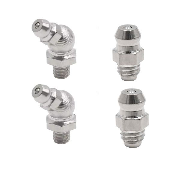
Standard Grease Fitting: The most commonly used type of grease fitting, often referred to as a “Zerk fitting,” features a straight nozzle and can be used in various applications. It is widely used in automotive and industrial machinery.

Angled Grease Fitting: This fitting has a 45° or 90° angle, making it easier to grease components that are difficult to access. It is ideal for tight spaces or when the fitting is mounted in a location that is not easily reached with a straight fitting.

Button Head Grease Fitting: A button-shaped fitting, typically used in situations where space is extremely limited or where it may need to be flush against a surface. These are ideal for industrial and automotive applications where space is a concern.

Rotary Grease Fittings are used in rotating components, such as machinery where parts are continuously turned, such as axles or wheels. The rotating motion ensures that the grease fitting doesn’t obstruct the machinery’s operation.

Straight Grease Fitting: This type has a simple straight design and is used for standard applications where the fitting can be easily accessed. It is the most common and widely recognized style.

Each type of grease fitting has been designed with specific applications and equipment in mind, ensuring the correct flow of lubricant to critical components in the machinery.

high pressure grease fittings supplier

B. Common Materials and Construction

Material Selection for Durability

Grease fittings are typically made from durable metals designed to withstand high pressures and exposure to the harsh conditions they often face in machinery environments. The most common materials used for grease fittings include:

Steel: The most common material for grease fittings, steel offers a good balance of strength and cost-effectiveness. It is capable of handling high-pressure grease flow and is resistant to wear and tear.

Stainless Steel: For more demanding environments, such as those with high humidity, corrosive substances, or high temperatures, stainless steel grease fittings are used. These fittings are highly resistant to rust, corrosion, and wear, making them ideal for heavy-duty and harsh working conditions.

Brass: Brass is sometimes used for grease fittings in low-pressure applications. It is more resistant to corrosion than steel but may not be as durable or pressure-resistant for heavy machinery.

Zinc-Plated Steel: Zinc plating offers additional protection against corrosion, making it suitable for applications where grease fittings are exposed to moisture or outdoor environments.

Aluminum: In applications where weight is a concern, aluminum fittings may be used. However, they are generally not as durable as steel or stainless steel and are better suited for light-duty applications.

Material selection is essential to ensure that the grease fitting can handle the specific pressure requirements and environmental conditions where it will be used. The material must also be resistant to corrosion, wear, and impact damage to ensure a long lifespan.

Why Proper Fitting Choice Matters in Different Machinery Environments

Choosing the right grease fitting depends on several factors, including the type of machinery, the operating environment, and the required lubrication. Proper fitting selection is crucial because an incompatible or inappropriate fitting can lead to:

Premature Failure: Using a fitting that is not suited for the operating pressures or environment may cause it to break, leak, or become clogged, which would ultimately affect the entire lubrication system.

Corrosion: In corrosive environments (e.g., exposure to saltwater or harsh chemicals), using a fitting made from low-grade material such as standard steel might result in rusting, leakage, and premature failure.

Inadequate Lubrication: If a grease fitting is poorly designed or constructed, it might not allow proper grease flow, leading to inadequate lubrication and resulting in increased friction, wear, and potential damage to machinery.

Common Causes of Broken Grease Fittings

A. Over-tightening or Under-tightening

How Incorrect Torque Can Damage Fittings

Grease fittings require precise torque to ensure a secure and effective seal without causing damage. Over-tightening or under-tightening the fitting can cause serious issues:

Over-tightening: When a grease fitting is tightened beyond the recommended torque, it can lead to several problems. The excessive pressure can crack or deform the fitting, potentially making it difficult to attach the grease gun or causing it to break under pressure. Over-tightening can also distort the thread, which might lead to leaks or an inability to properly deliver grease.

Under-tightening: On the other hand, under-tightening a grease fitting can prevent it from creating a proper seal, resulting in grease leakage. Inadequate sealing also compromises the flow of lubrication to the system’s moving parts, which can cause friction and premature wear of components.

Signs of Improper Tightening and Risks Involved

Visible Cracks or Deformation: A fitting that has been over-tightened may show signs of cracks or deformities around the threads or the head.

Leakage: If a fitting is under-tightened, you may notice grease leaking around the fitting during lubrication.

Grease Infiltration Issues: A poorly tightened fitting may fail to deliver adequate lubrication to the necessary components, leading to increased friction and eventual component failure.

The risks involved include reduced equipment lifespan, frequent downtime, and potential damage to both the fitting and the surrounding machinery, leading to costly repairs.

Grease Fitting Clogged

B. Corrosion and Wear

Environmental Factors Leading to Corrosion

Grease fittings are often exposed to harsh environmental conditions, which can lead to corrosion over time. Some of the most common environmental factors contributing to fitting degradation include:

Humidity: In moist or humid environments, moisture can accumulate on the fittings, leading to rust and corrosion, especially in metal fittings that are not corrosion-resistant. This weakens the fitting material and reduces its lifespan.

Chemical Exposure: Chemicals, including acids, salts, or industrial cleaners, can accelerate the corrosion process. These substances can break down the metal, causing pitting and weakening the fitting structure.

Extreme Temperatures: High heat can cause metal to expand, leading to cracks or deformities, while extreme cold can make fittings brittle and more prone to cracking or breaking when force is applied.

How Regular Wear Affects Grease Fittings Over Time

Over time, grease fittings can wear out due to the constant pressure applied by the grease gun, exposure to contaminants, and environmental elements. As a result:

The fitting’s sealing ability can degrade, leading to grease leakage or loss of pressure during lubrication.

The fitting can become clogged with dirt, grease residue, or other debris, obstructing the flow of lubricant.

Wear and tear from constant movement or vibration can loosen or damage the fitting, causing it to fail and require replacement.

Regular inspection and maintenance are essential to detect early signs of wear and prevent more serious problems from developing.

C. Impact Damage

External Factors

Grease fittings are small, often located in tight spaces, and are vulnerable to impact damage. Common sources of impact include:

Tools: Mishandling tools, such as using the wrong size grease gun nozzle or applying excessive force, can cause the fitting to break or become misaligned.

Equipment: In high-impact areas, such as machinery that experiences vibration or machinery that undergoes frequent starts and stops, grease fittings can be subjected to physical forces that lead to cracks or dislodgement.

Rough Handling: During maintenance or repairs, grease fittings may get damaged due to improper handling or accidental impact when moving parts of the system.

Effects of Sudden Pressure Spikes or System Surges

Pressure Surges: In some hydraulic systems, pressure surges can occur when there is a sudden increase in system pressure due to system irregularities or malfunctioning components. These pressure spikes can damage fittings by causing them to dislodge, crack, or become misaligned.

Impact from Vibration: In systems subject to constant vibration or jolts (e.g., on trucks, construction machinery), fittings can be subjected to repeated impacts that weaken the fitting’s structure over time, causing them to break or fail unexpectedly.

D. Inadequate Lubrication

Poor Grease Quality or Improper Grease Application

Grease fittings rely on the proper quality and quantity of grease to lubricate machinery components effectively. Using poor-quality grease or the wrong type of lubricant for the specific application can cause several issues:

Inadequate Lubrication: Using grease that is too thick or too thin can lead to poor lubrication, increasing friction and wear on moving parts.

Contaminated Grease: A grease that contains contaminants like dirt or moisture can clog the grease fitting or cause abrasive wear on components.

Improper Application: Fittings that are not adequately greased may suffer from early signs of wear and tear. Over-greasing, on the other hand, can cause the grease to seep out and lead to contamination or loss of pressure.

How Lack of Maintenance Accelerates Fitting Failure

Without regular maintenance, grease fittings can become clogged, worn, or damaged. Over time, this lack of attention can cause the fitting to fail. For instance:

Clogging: If a fitting isn’t regularly lubricated or maintained, debris can accumulate in the fitting, causing it to become clogged and preventing the proper flow of grease.

Lack of Pressure: As grease degrades or if the lubrication system is neglected, the amount of pressure required to deliver grease through the fitting decreases, leading to inadequate lubrication and increased friction.

Neglecting to maintain grease fittings often accelerates the wear process, causing the fitting to fail prematurely and potentially leading to more severe machinery issues.

E. Poor Installation or Faulty Fittings

Manufacturing Defects in Fittings

Not all broken grease fittings are the result of wear or external factors. Manufacturing defects can contribute to fitting failures. Common defects include:

Incorrect Threading: Fittings with improperly threaded parts may not fit securely, leading to leaks or failures in sealing.

Weak Material: Some fittings may be made with materials that aren’t up to standard or poorly processed, leading to a weakened structure that can break or deform easily.

Defective Seals: Fittings that lack proper seals or gaskets may leak grease, causing inadequate lubrication and eventual breakdown of the fitting.

Mistakes During the Initial Installation Process

During installation, several mistakes can compromise the functionality of grease fittings, such as:

Misalignment: If a grease fitting is not aligned properly with the lubrication point, it may not provide adequate grease flow, leading to lubrication failure.

Sealing Issues: If the fitting’s seal isn’t properly secured, it may leak grease or fail to maintain adequate pressure, causing premature failure of both the fitting and the surrounding components.

Incorrect Size or Type: Installing the wrong size or type of fitting for a specific application can cause it to malfunction, especially if the fitting doesn’t fit properly with the system’s lubrication channels or if it is incompatible with the type of grease used.

Preventative Measures for Avoiding Broken Grease Fittings

A. Correct Installation Practices

Ensuring Proper Fitting Selection for Specific Equipment

The first step in preventing broken grease fittings is ensuring the right type of fitting is selected for each specific application. Different machinery and operating environments have varying lubrication needs, which dictate the fitting type and material:

Type Selection: Choose fittings based on the operational needs of the equipment. For instance, use angled or rotary fittings for hard-to-reach areas, button-head fittings in tight spaces, and straight fittings where they can be easily accessed.

Material Selection: Depending on the environment, you should opt for corrosion-resistant materials like stainless steel or zinc-plated fittings if the equipment is exposed to moisture, chemicals, or extreme temperatures.

Ensuring that fittings are designed to handle the expected pressure and environmental conditions helps reduce the risk of fitting failure.

Step-by-Step Guide on Installing Grease Fittings Correctly

Check Compatibility: Verify that the selected grease fitting matches the equipment and is compatible with the intended grease type.

Clean the Installation Area: Ensure the area where the fitting will be installed is clean and free of debris to prevent contamination that could affect the seal.

Align the Fitting: Ensure the fitting is properly aligned with the lubrication point. This ensures that grease is delivered efficiently without excess force.

Install the Fitting: Thread the fitting into place carefully by hand to avoid cross-threading. Use the appropriate tool to tighten it securely.

Torque Application: Apply the correct torque to avoid over-tightening or under-tightening, both of which can lead to fitting damage or failure.

Inspect for Leaks: Once installed, check the fitting for leaks to ensure that it is sealed correctly.

By following proper installation practices, you can significantly extend the life of the grease fitting and ensure that the lubrication system functions properly.

B. Regular Inspection and Maintenance

Developing a Maintenance Schedule for Checking Grease Fittings

Regular inspection is critical to identifying issues early and preventing broken grease fittings. Develop a comprehensive maintenance schedule that includes:

Routine Inspections: Check grease fittings at least every few weeks or months depending on the machine’s usage. Look for signs of damage, wear, corrosion, or leakage.

Lubrication Monitoring: Ensure that grease is applied at regular intervals. If grease fittings are clogged, damaged, or leaking, address them immediately.

Monitoring Pressure: Ensure that the system’s pressure is within the manufacturer’s recommended levels to avoid stress on the fittings.

Using Diagnostic Tools to Monitor Fitting Conditions

In addition to visual inspection, diagnostic tools can be used to assess the condition of grease fittings:

Grease Pressure Testers: These tools can help determine if the grease is being delivered properly through the fitting and if there are any blockages or pressure anomalies.

Infrared Thermometers: Use infrared thermometers to monitor temperature changes around fittings, as unusual temperature rises could indicate problems with lubrication or a failing fitting.

Ultrasonic Testing: For advanced diagnostics, ultrasonic sensors can detect signs of wear, corrosion, or vibration that might suggest a failing grease fitting.

By regularly inspecting and maintaining grease fittings, you can catch minor issues before they become major problems, reducing downtime and repair costs.

grease Fittings install Topa

C. Use of Quality Materials

Choosing Corrosion-Resistant and Durable Materials for Fittings

The material used for grease fittings plays a significant role in their durability and resistance to environmental factors. Selecting the appropriate material for fittings can prevent premature failure caused by corrosion, wear, and stress:

Stainless Steel: Ideal for harsh environments, stainless steel is resistant to corrosion from chemicals, moisture, and high temperatures, making it a top choice for heavy-duty machinery.

Zinc-Plated Steel: Provides additional corrosion resistance for environments that may experience rust, but it’s still affordable and effective for less demanding conditions.

Brass: While softer than steel, brass is used in applications where low pressure and light-duty use are required.

Durable Seals and Gaskets: Ensure that fittings come with high-quality seals or gaskets that can withstand heat, pressure, and contaminants.

The Role of High-Quality Grease in Prolonging Fitting Life

Using high-quality grease is just as important as selecting durable fittings. High-quality grease provides better lubrication, reduces friction more effectively, and prevents the buildup of contaminants. Choose grease specifically formulated for the equipment and operating conditions:

Consistency: Choose grease with the correct viscosity for the application. Grease that is too thick may cause clogging, while grease that is too thin may leak or fail to provide proper lubrication.

Additives: High-quality greases contain additives that help protect against oxidation, corrosion, and wear, which extends the life of the grease fitting and the components being lubricated.

D. Proper Torque Application

How to Use Torque Wrenches and Avoid Over-tightening

Torque application is critical when installing grease fittings, as both over-tightening and under-tightening can lead to issues. To avoid damage:

Use a Torque Wrench: Always use a torque wrench to apply the specified torque when installing a grease fitting. This ensures that the fitting is neither too tight nor too loose.

Avoid Over-tightening: Over-tightening a fitting can distort or crack the fitting, causing leaks, excessive stress on components, and possible fitting failure. The torque should be applied according to the manufacturer’s specifications, typically between 10 and 30 foot-pounds.

Proper Re-tightening: For fittings that may need periodic re-tightening, ensure that the torque specification is followed carefully to avoid damaging the fitting or surrounding parts.

Recommended Torque Specifications for Different Fitting Types

Torque specifications vary depending on the fitting type and size. It is essential to follow manufacturer guidelines for each type of fitting to avoid common issues:

Standard Grease Fittings: Typically, these require around 10–20 ft-lbs of torque.

Angled or Button Head Fittings: These fittings might require slightly less torque due to their design but should be tightened to the specifications provided by the manufacturer.

Heavy-Duty Fittings: Larger, heavy-duty fittings for industrial or agricultural machinery may require up to 30 ft-lbs of torque.

Following the correct torque specifications reduces the likelihood of damage and ensures that the fittings maintain their seal and pressure.

E. Environmental Considerations

Preventing Exposure to Harmful Elements Like Water, Salt, and Chemicals

Exposure to environmental factors such as water, salt, chemicals, or extreme temperatures can accelerate the breakdown of grease fittings. To prevent environmental damage:

Protect Fittings from Moisture: Ensure that grease fittings are kept dry and protected from excessive moisture or standing water, which can cause corrosion.

Use Protective Covers or Shields: Install protective covers or shields to shield grease fittings from external elements like dust, dirt, salt, and chemicals. This is particularly important for machinery used in marine environments or outdoors.

Regularly Clean Fittings: Clean grease fittings periodically to remove any accumulated debris, dirt, or grease buildup that might attract moisture or contaminants.

Implementing Protective Covers or Shields

Protective covers or boots can be used to shield grease fittings from damage in harsh environments. These covers protect the fitting from direct exposure to the elements, reducing the risk of corrosion, wear, and contamination. Use covers that are durable and specifically designed for grease fittings to ensure they remain effective over time.

Conclusion

We encourage you to prioritize grease fitting maintenance in your routine equipment care. Ensure that your fittings are in top condition, replace any worn-out or damaged parts, and don’t hesitate to reach out to professionals for assistance when needed.


FAQ

What are grease fittings and why are they important?

Grease fittings, also known as grease nipples, are components used to inject lubricants into machinery to reduce friction and wear. They are crucial for maintaining equipment, ensuring smooth operation, and extending the lifespan of moving parts.

What causes grease fittings to break?

Common causes include over-tightening or under-tightening, corrosion from environmental factors, impact damage, inadequate lubrication, and poor installation.

How can I prevent my grease fittings from breaking?

Preventative measures include using the correct fittings, applying the proper torque, regular inspections, using quality materials, and protecting fittings from environmental damage.

How often should I inspect grease fittings?

It is recommended to inspect grease fittings regularly, at least once a month or every few weeks depending on usage and environmental conditions. Routine checks can catch issues early.

What should I do if a grease fitting is damaged or leaking?

If a grease fitting is damaged or leaking, replace it immediately. Continuing to use a damaged fitting can lead to equipment failure or inefficiency in the lubrication system.

Can I install grease fittings myself?

Yes, as long as the proper installation procedures are followed. Ensure the fitting is aligned, torqued correctly, and compatible with the machinery. If you’re unsure, consulting a professional is a good idea.

Contact Topa

Save 30% on maintenance costs with our easy-install hydraulic fittings. Contact Now!