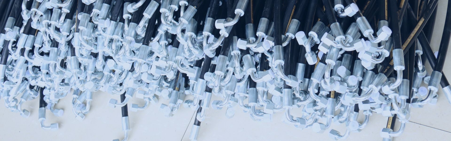
The use of the wrong type of hydraulic fitting, a critical connection point in fluid power systems, can lead to disastrous consequences ranging from minor leaks to system inefficiencies and even complete failure and safety hazards. Three major standards dominate the hydraulic fitting market – Metric vs American vs British – each of which has evolved independently to meet regional industry needs, creating incompatible thread forms, sealing methods and dimensional specifications, making accurately identifying and differentiating between these standards an essential skill for maintenance technicians, engineers and purchasing professionals.
Understanding Hydraulic Fitting Standards
Historical Development of Fitting Standards
The development of hydraulic fitting standards parallels the industrial evolution of their regions of origin, with each standard reflecting different engineering philosophies and industrial needs.
Metric Standards emerged primarily from German and French industrial development in the early 20th century. The DIN (Deutsches Institut für Normung) standards, particularly DIN 2353 for 24° cone fittings, became widely adopted throughout Europe. These were later harmonized under ISO standards, creating a consistent international metric system. The metric approach emphasizes systematic, decimal-based measurements and standardized thread pitches.
American Standards developed during the rapid industrialization of the United States in the late 19th and early 20th centuries. The Society of Automotive Engineers (SAE) and American National Standards Institute (ANSI) established standards like JIC (Joint Industry Council) 37° flare fittings and NPT (National Pipe Thread) tapered threads. American standards typically use fractional inch measurements and varying thread counts per inch.
British Standards evolved from the early days of the Industrial Revolution, with the British Standards Institution (BSI) formalizing the Whitworth thread form in the mid-19th century. British Standard Pipe (BSP) threads, both parallel (BSPP) and tapered (BSPT), became widely used throughout the British Empire and Commonwealth countries. These standards use inch-based measurements but with unique thread forms and pitches.
Key standardization organizations continue to maintain and develop these standards:
- ISO (International Organization for Standardization) for metric standards
- SAE, ANSI, and ASME for American standards
- BSI for British standards
While globalization has led to some convergence and cross-compatibility, regional preferences remain strong. Metric fittings dominate in Europe, Asia, and most developing markets; American standards prevail in North America and in industries with American origins (like aerospace); British standards remain common in former Commonwealth countries and certain industries like marine applications.
Basic Terminology and Components
Understanding the fundamental terminology and components of hydraulic fittings is essential before delving into the specific differences between standards.
Thread Types:
- Parallel Threads maintain the same diameter throughout their length. They typically require additional sealing mechanisms like O-rings or washers (examples: BSPP, metric parallel).
- Tapered Threads gradually decrease in diameter, creating a wedging action that helps form a seal when tightened (examples: NPT, BSPT).
Sealing Mechanisms:
- Cone Sealing uses a metal-to-metal contact between a cone-shaped surface and a corresponding seat (examples: 24° DIN cone, 37° JIC flare).
- O-ring Sealing employs an elastomeric ring compressed in a groove to create a seal (examples: SAE O-ring, metric O-ring).
- Flat Sealing uses a washer or bonded seal compressed between two flat surfaces (example: BSPP with bonded seal).
Key Components:
- Nut (or coupling): The rotating component with internal threads that pull the assembly together.
- Body (or fitting): The main component with either internal or external threads that connects to the system.
- Sealing Surface: The area where the pressure seal is formed, which varies by fitting type.
Thread Terminology:
- Major Diameter: The largest diameter of a thread (measured across the peaks).
- Minor Diameter: The smallest diameter of a thread (measured across the roots).
- Pitch: The distance between adjacent thread peaks.
- In metric: Expressed directly in millimeters (e.g., 1.5mm pitch).
- In American/British: Expressed as threads per inch (TPI) (e.g., 18 TPI).
- Thread Angle: The angle between the flanks of the thread (60° for metric, 55° for Whitworth, 60° for UN/UNF).
Understanding these basic concepts provides the foundation for identifying and distinguishing between the different fitting standards we’ll explore in the following sections.
Metric Fitting Characteristics
Metric Thread Identification
Metric hydraulic fittings use a standardized thread system that follows the ISO metric thread standards. The thread designation format provides key information about the fitting’s dimensions and characteristics.
Thread Designation Format:
A typical metric thread is designated as M27×1.5, where:
- “M” indicates a metric thread
- “27” represents the nominal major diameter in millimeters
- “1.5” indicates the thread pitch in millimeters
For hydraulic applications, common metric thread sizes range from M8 to M42, with the most frequently used sizes being M14, M16, M18, M22, M27, and M33.
Measurement Techniques:
To identify a metric thread:
- Measure the major diameter using calipers. For internal threads (like in a nut), measure the inner diameter and add approximately 2mm to estimate the thread size.
- Determine the thread pitch using a metric thread pitch gauge.
- Observe the thread angle, which should be 60° for metric threads.
Distinguishing Features:
- Metric threads always use the same pitch for a given diameter (unlike American threads which may have different TPI options for the same diameter).
- Sizes are in whole millimeter increments (M14, M16, etc.).
- Thread pitch is typically finer for larger diameters.
Metric Fitting Sealing Systems
Metric hydraulic fittings employ several distinct sealing systems, each with specific applications and identification features.
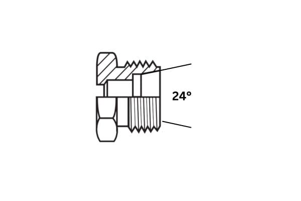
DIN 2353 (24° Cone):
The most common metric hydraulic fitting system uses a 24° cone sealing principle. These fittings consist of:
- A fitting body with a 24° cone seat
- A cutting ring (or ferrule)
- A nut that compresses the cutting ring onto the tube
The cutting ring creates two sealing points: one between the ring and tube, and another between the ring and the cone seat. These fittings are identified by:
- The 24° cone angle (compared to 37° in JIC fittings)
- Metric thread sizes
- Often marked with “L” (light series), “S” (heavy series), or “LL” (very light series)
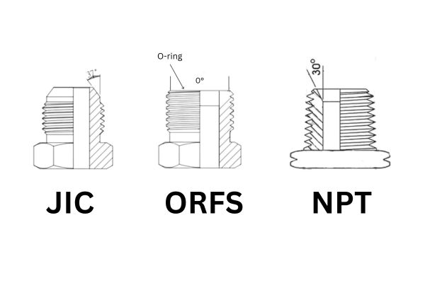
Metric O-ring Face Seal (ORFS):
This system uses an O-ring compressed against a flat face to create a seal. Features include:
- A flat-faced fitting with an O-ring groove
- A straight thread that doesn’t participate in sealing
- Metric thread sizes
- Often used in high-pressure applications where vibration resistance is important
Metric Flat Face Seal:
Similar to ORFS but using a flat washer or bonded seal instead of an O-ring. Characteristics include:
- Flat sealing surfaces
- A separate washer or bonded seal
- Metric thread sizes
- Often used in lower-pressure applications
Visual Identification:
Metric fittings can often be visually identified by:
- Clean, precise machining with minimal tool marks
- Metric size markings (e.g., M22×1.5)
- European manufacturer marks (e.g., Ermeto, Voss, Mannesmann)
- Often have a bright zinc-plated finish
- DIN or ISO standard markings
Metric fittings have become increasingly common worldwide due to their systematic sizing and standardization, making them the preferred choice for many new hydraulic system designs outside North America.
American Fitting Characteristics
American Thread Identification
American hydraulic fittings utilize several thread standards, each with distinct characteristics and applications. Understanding these standards is crucial for proper identification.
Thread Designation Format:
A typical American thread might be designated as 9/16-18 UNF, where:
- “9/16” represents the nominal major diameter in inches
- “18” indicates threads per inch (TPI)
- “UNF” specifies the thread series (Unified National Fine)
Common American thread standards in hydraulic applications include:
SAE (Society of Automotive Engineers):
- Uses Unified National thread series (UN, UNF, UNEF)
- Common in mobile hydraulics and automotive applications
- Typically uses straight threads with O-ring seals
- Designated by dash numbers (e.g., -6, -8, -10) corresponding to 1/16″ increments
NPT (National Pipe Thread):
- Tapered thread that creates a seal through thread deformation
- Used in lower-pressure applications
- Designated in nominal pipe sizes (e.g., 1/4″, 1/2″)
- 1° 47′ taper angle (approximately 1/16″ per inch)
JIC (Joint Industry Council):
- Uses 37° flared tube fitting standard
- Common in industrial hydraulics
- Typically uses UNF threads
- Designated by tube OD size
Measurement Techniques:
To identify American threads:
- Measure the major diameter in inches
- Use a thread pitch gauge to determine threads per inch
- Check for taper (present in NPT, absent in UN series)
- Observe the thread angle (60° for UN series)
Distinguishing Features:
- Sizes in fractions of an inch
- Thread count expressed as TPI (threads per inch)
- Multiple thread series may use the same diameter but different TPI
American Fitting Sealing Systems
American hydraulic fittings employ several distinct sealing methods, each with specific applications and identification characteristics.
JIC 37° Flare:
One of the most common American hydraulic fitting types, featuring:
- A 37° flared tube end
- A 37° cone seat in the fitting
- Metal-to-metal sealing without additional sealing elements
- UNF threads that don’t participate in sealing
- Identified by the distinctive 37° angle (compared to 24° in metric fittings)
- Often used in high-pressure, high-vibration applications
SAE O-ring Face Seal:
Similar to metric ORFS but following SAE standards:
- Flat-faced fitting with an O-ring groove
- Straight threads that don’t participate in sealing
- Inch-based dimensions
- Often used in high-pressure applications requiring frequent disassembly
- Identified by the visible O-ring and flat face
NPT/NPTF Tapered Thread Seal:
Creates a seal through the thread itself:
- Tapered external and internal threads
- Often requires thread sealant (tape or paste)
- NPTF (Dryseal) version designed to seal without sealant
- Identified by the tapered profile and coarser thread form
- Common in lower-cost systems and pipe connections
Visual Identification:
American fittings can often be visually identified by:
- Fractional size markings (e.g., 3/4″)
- SAE or JIC markings
- North American manufacturer marks (e.g., Parker, Eaton)
- Often have a yellow or clear zinc-plated finish
- SAE or AN standard markings
American fittings remain dominant in North American industrial and mobile hydraulic applications, as well as in aerospace and military applications worldwide due to the influence of American military standards.
British Fitting Characteristics
British Thread Identification
British hydraulic fittings primarily use the British Standard Pipe (BSP) thread system, which comes in two main variants: parallel and tapered. Understanding their characteristics is essential for proper identification.
Thread Designation Format:
British threads are typically designated as G 1/2 or R 1/2, where:
- “G” indicates BSPP (parallel)
- “R” indicates BSPT (tapered)
- “1/2” represents the nominal size in inches
The key British thread standards used in hydraulic applications are:
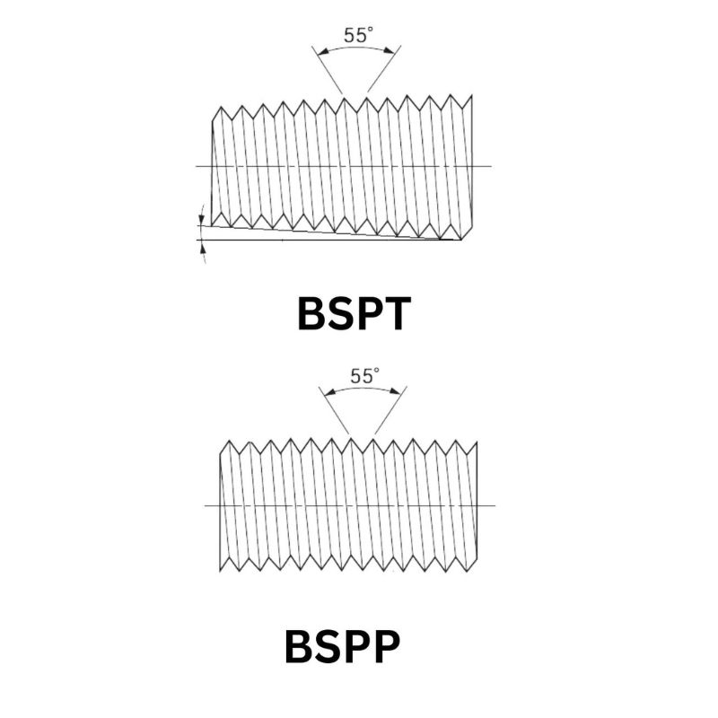
BSPP (British Standard Pipe Parallel) – G Thread:
- Parallel thread that maintains the same diameter throughout
- Requires additional sealing method (bonded seal, O-ring, or metal cone)
- Common in European hydraulic systems and worldwide in certain industries
- Uses Whitworth thread form with 55° thread angle
BSPT (British Standard Pipe Taper) – R Thread:
- Tapered thread that creates a wedging action for sealing
- Similar in concept to NPT but with different thread form
- 1° 47′ taper angle (approximately 1/16″ per inch)
- Uses Whitworth thread form with 55° thread angle
Measurement Techniques:
To identify British threads:
- Measure the major diameter in inches
- Use a thread pitch gauge to determine threads per inch
- Check for taper (present in BSPT, absent in BSPP)
- Observe the thread angle (55° for Whitworth thread form)
- Compare to reference charts, as nominal sizes don’t directly correspond to actual dimensions
Distinguishing Features:
- Whitworth thread form with 55° angle (compared to 60° in metric and American)
- Rounded thread roots and crests
- Thread pitch expressed in threads per inch but following specific BSP standards
- Nominal sizes that don’t directly match the thread diameter
British Fitting Sealing Systems
British hydraulic fittings employ several sealing methods, each with specific applications and identification features.
BSPP with Bonded Seal:
A common configuration using a BSPP thread with a bonded seal washer:
- Parallel thread with a 30° chamfer at the end
- Bonded seal (elastomer bonded to a metal washer) compressed against a flat face
- Metal-to-elastomer sealing
- Identified by the flat face on the male fitting and the separate bonded seal
- Common in European mobile and industrial hydraulics
BSPP with O-ring:
An alternative sealing method for BSPP threads:
- Parallel thread with an O-ring groove
- O-ring compressed against a 30° chamfered seat
- Identified by the visible O-ring on the male fitting
- Often used in higher-pressure applications
BSPT Tapered Thread Seal:
Creates a seal through the thread itself:
- Tapered external and internal threads
- Often requires thread sealant (tape or paste)
- Identified by the tapered profile and Whitworth thread form
- Common in lower-pressure applications and pipe connections
Visual Identification:
British fittings can often be visually identified by:
- BSP or G/R markings
- Inch-based nominal size markings (e.g., 1/2″)
- European or Commonwealth manufacturer marks
- Often have a bright zinc-plated finish
- Whitworth thread form with rounded roots and crests
- Bonded seals with colored (often copper or fiber) washers
British fittings remain common in European hydraulic systems, particularly in older equipment, and in Commonwealth countries. They’re also prevalent in the marine industry worldwide.
Hydraulic Fitting Visual Identification Comparison Table
identification Feature | Metric Fittings | American Fittings | British Fittings |
| Thread Angle & Form | 60°angle with sharp roots and crests | 60°angle with inch dimensions | 55°angle with rounded roots and crests(Whitworth) |
| Sealing Surface Geometry | 24°cone (DIN standard) | 37°flare(JIC) /Flat face with O-ring (ORFS) | 30°chamfer(BSPP) /Flat face with bonded seal |
| Markings & Stamps | M14×1.5/ DIN 2353/ISO 8434 | SAE J514, 9/16-18UNF, NPT 1/4 | G1/2/BSPP/BSP 1/4 |
| Surface Finish & Appearance | Bright zinc finish | Yellow or clear zinc plating | Various finishes,often with colored bonded seals/washers |
| Component Configuration | Separate nuts and bodies common (DIN 2353) | One-piece designs common n NPT fittings | – |
| Sealing Method | Metal-to-metal cone sealing/ O-ring sealing | Flare metal-to-metal sealing /O-ring face sealing /NPT thread sealing | BSPP bonded seal/BSPT thread sealing |
Common Identification Challenges
Even with proper tools and techniques, several challenges can complicate hydraulic fitting identification:
Similar-Sized Threads Across Standards:
Some thread sizes are very close in dimensions:
- M14×1.5 (metric) vs. 9/16″-18 (UNF)
- G 1/4 (BSPP) vs. 1/4″ NPT
- M10×1.0 vs. 3/8″-24 UNF
In these cases, careful measurement of thread angle and pitch is crucial.
Worn or Damaged Threads:
- Corrosion, wear, or impact damage can alter thread dimensions
- Thread sealant residue can obscure thread form
- Damaged sealing surfaces may not reveal original geometry
Unmarked or Non-Standard Fittings:
- Older fittings may lack identifying marks
- Some manufacturers use proprietary variations
- Counterfeit parts may not conform to any standard
Hybrid or Proprietary Systems:
Some equipment uses:
- Proprietary thread forms
- Modified standard threads
- Combination of different standard elements
- Special sealing systems
Troubleshooting Approaches:
- Clean threads thoroughly before measurement
- Check multiple parameters, not just the diameter
- Consider the equipment origin (European, American, etc.)
- Consult manufacturer documentation when available
- Use trial fitting with known standards (carefully and without force)
- When in doubt, replace with complete assemblies rather than mixing components
Best Practices and Common Mistakes
Fitting Selection Guidelines
Selecting the appropriate hydraulic fitting involves considering multiple factors beyond simply matching thread types.
Application-Specific Considerations:
- Mobile Equipment: Vibration resistance is critical—JIC 37° flare and ORFS fittings excel here
- Stationary Industrial: Ease of assembly and maintenance may favor BSPP with bonded seals or metric fittings
- High-Pressure Systems: Select fittings with appropriate pressure ratings and safety factors
- Frequent Disassembly: O-ring face seal types (ORFS, SAE) allow multiple reassemblies without degradation
- Space Constraints: Compact designs may favor certain fitting types over others
Pressure and Temperature Factors:
- Verify pressure ratings for the specific fitting size and material
- Apply appropriate safety factors (typically 4:1 for hydraulic systems)
- Consider pressure spikes and impulse loading
- Account for temperature effects on material strength
- Evaluate temperature effects on sealing materials (especially O-rings)
Material Compatibility:
- Carbon Steel: Economical but requires corrosion protection
- Stainless Steel: For corrosive environments or high-temperature applications
- Brass: For lower-pressure systems and certain compatible fluids
- Sealing Materials: Ensure O-rings and bonded seals are compatible with the hydraulic fluid
- Plating/Coating: Consider environmental exposure and corrosion requirements
Industry-Specific Standards:
- Aerospace: AN and MS fittings with specific material and testing requirements
- Marine: Corrosion-resistant materials and often BSPP standards
- Food Processing: Stainless steel with specific surface finish requirements
- Mining: Heavy-duty designs with enhanced corrosion and abrasion resistance
- Mobile Equipment: SAE standards often prevail
System Consistency:
- Maintain the same fitting standard throughout a system when possible
- Document any mixed standards clearly for maintenance purposes
- Consider standardization during system upgrades
Common Mistakes and Troubleshooting
Even experienced technicians can encounter issues with hydraulic fittings. Understanding common mistakes and their solutions can prevent costly downtime and safety hazards.
Cross-Threading Issues:
- Causes: Misalignment during assembly, damaged threads, incorrect thread identification
- Prevention: Align properly before tightening, verify thread type, turn counterclockwise until thread “clicks” into place
- Solution: Replace both mating components if cross-threading occurs; never force assembly
Overtightening Problems:
- Causes: Lack of torque specifications, misconception that tighter is better
- Prevention: Use torque specifications, understand that sealing occurs at specific points not through excessive force
- Solution: Replace damaged components, implement proper torque procedures
Mismatched Thread Standards:
- Causes: Incorrect identification, mixed inventory, improper documentation
- Prevention: Clear labeling, thread verification before assembly, system standardization
- Solution: Use proper adapters, never force connections that don’t thread smoothly
Incorrect Sealing Method Application:
- Causes: Using thread sealant where not required, omitting seals, reusing damaged seals
- Prevention: Understand each fitting type’s sealing mechanism, inspect sealing surfaces
- Solution: Clean components thoroughly, replace damaged sealing elements
Common Leakage Points and Solutions:
- Thread Leaks: Usually indicates incorrect thread type or missing sealant where required
- Connection Interface Leaks: Check for damaged sealing surfaces, proper alignment, and correct sealing components
- Vibration-Induced Leaks: Ensure proper torque, consider using thread lockers where appropriate
- Pressure Spike Leaks: Verify fitting pressure rating is appropriate for the application including transient pressures
Systematic Troubleshooting Approach:
- Identify the exact location of the leak
- Determine the fitting type and sealing method
- Depressurize and disassemble carefully
- Inspect all components for damage
- Verify correct parts and assembly method
- Reassemble with proper technique and torque
- Document any changes for future reference
Conclusion
The differences between Metric, American, and British hydraulic fittings reflect their independent development histories and the industrial needs of their regions of origin. While this diversity creates challenges for global operations and maintenance, understanding these differences enables proper identification, selection, and application of hydraulic fittings across various systems.
Appendices
Glossary of Terms
ANSI: American National Standards Institute, an organization that oversees the development of standards in the United States.
BSI: British Standards Institution, the national standards body of the United Kingdom.
Pitch: The distance between adjacent thread peaks, expressed in millimeters for metric threads.
Tapered Thread: A thread that gradually decreases in diameter to create a wedging action for sealing.
TPI: Threads Per Inch, the number of thread peaks per inch of length, used in imperial measurements.
UN: Unified National, a thread standard used in the United States and Canada.
UNF: Unified National Fine, a fine-pitch version of the UN thread standard.
Whitworth Thread: A British thread form with a 55° thread angle and rounded roots and crests.
FAQ
How can I quickly distinguish between Metric, American, and British hydraulic fittings?
The fastest way is to check thread angle and form: Metric has 60° angle with sharp threads, American has 60° angle with inch dimensions, and British Whitworth has 55° angle with rounded threads.
What tools do I need to properly identify an unknown hydraulic fitting?
Essential tools include calipers for measuring diameter, thread pitch gauges (both metric and imperial), a magnifying glass to examine thread form, and reference charts for comparing measurements to standard sizes.
Can I connect fittings from different standards using adapters?
Yes, adapters are available to connect between different standards, but they add potential leak points and may restrict flow. Always verify that adapters meet or exceed the system’s pressure rating and ensure proper installation with appropriate torque specifications.
What are the most common mistakes when working with hydraulic fittings?
Common mistakes include cross-threading due to misalignment, overtightening fittings (especially NPT), using thread sealant where not required, misidentifying thread standards, and failing to use backing wrenches during installation which can damage components.
How do sealing methods differ between the three major fitting standards?
Metric fittings typically use 24° cone metal-to-metal sealing, American JIC fittings use 37° flare sealing, American NPT uses tapered thread sealing, and British BSPP often uses bonded seals or O-rings against a flat or 30° chamfered surface.
What happens if I use the wrong fitting in a hydraulic system?
Using the wrong fitting can lead to immediate leakage, system pressure loss, contamination ingress, or catastrophic failure under pressure. Even if it initially appears to work, improper fittings may fail prematurely, potentially causing equipment damage, environmental hazards, or safety risks.