Selecting the appropriate hydraulic hose is paramount for optimizing the performance, reliability, and cost-effectiveness of any hydraulic system. A critical, yet often overlooked, aspect of hydraulic hose selection is its internal layer structure. This comprehensive guide delves into the intricacies of single-layer, double-layer, and multi-layer hydraulic hoses, providing technical engineers and product selection personnel with the knowledge to make informed decisions.
Understanding Hydraulic Hose Construction
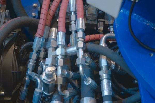
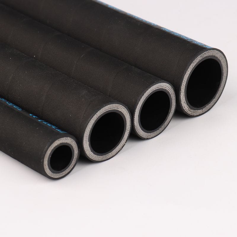
A hydraulic hose is a complex engineered component designed to safely and efficiently transmit hydraulic fluid under varying pressures and temperatures. Its construction typically comprises three primary layers, each serving a distinct purpose:
Core Tube: The Fluid Conduit
The innermost layer, the core tube, is responsible for containing and conveying the hydraulic fluid. Its material composition is crucial for chemical compatibility with the fluid, as well as resistance to heat and pressure. Common materials include synthetic rubber (such as Nitrile, Neoprene, or EPDM) and thermoplastics (like Nylon or Polyester). The choice of material directly impacts the hose’s temperature range and its ability to withstand degradation from the hydraulic fluid.
Reinforcement Layers: The Strength Behind the Pressure
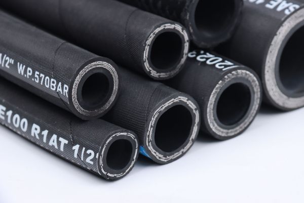
The reinforcement layers are the backbone of the hydraulic hose, providing the necessary strength to withstand internal pressure and external forces. These layers are typically made from high-tensile materials, such as steel wire or synthetic fibers, and are applied in various configurations to achieve different pressure ratings and flexibility characteristics. The number and type of reinforcement layers are the primary determinants of a hose’s working pressure and burst strength.
Single-Layer Reinforcement Hoses
Single-layer reinforcement hoses, often referred to as one-wire braid (1WB) hoses (e.g., SAE 100R1), feature a single braid of high-tensile steel wire or textile fiber. These hoses are generally designed for low to medium-pressure applications. Their simpler construction offers greater flexibility and a smaller bend radius compared to multi-layered hoses, making them suitable for applications with tight routing constraints. They are commonly found in:
- Low-pressure return lines: Where fluid is returned to the reservoir with minimal pressure.
- Air and vacuum lines: Applications that do not involve high hydraulic pressures.
- Agricultural machinery: For less demanding hydraulic circuits.
- General industrial applications: Where moderate pressure and good flexibility are required.
Double-Layer Reinforcement Hoses
Double-layer reinforcement hoses, commonly known as two-wire braid (2WB) hoses (e.g., SAE 100R2), incorporate two braids of high-tensile steel wire. This additional layer significantly increases the hose’s working pressure capacity and burst strength, making them suitable for a wider range of medium to high-pressure hydraulic systems. While less flexible than single-layer hoses, they still offer a good balance of pressure capability and maneuverability. They are widely used in:
- Construction equipment: Excavators, loaders, and bulldozers.
- Mining machinery: For moderate to high-pressure hydraulic circuits.
- Material handling equipment: Forklifts and cranes.
- General industrial hydraulic systems: Where higher pressures are encountered.
Multi-Layer Reinforcement Hoses
Multi-layer reinforcement hoses, often referred to as multi-spiral hoses, feature multiple (typically four or six) spiraled layers of high-tensile steel wire. This construction provides exceptional pressure resistance, making them ideal for very high-pressure and heavy-duty applications with significant pressure surges. While offering superior strength, multi-spiral hoses are generally less flexible and have a larger bend radius compared to braided hoses. Their primary applications include:
- Heavy construction equipment: Large excavators, mining trucks, and drilling rigs.
- Oil and gas industry: High-pressure lines in drilling and production.
- Forestry equipment: For demanding hydraulic systems.
- High-pulse applications: Where rapid pressure fluctuations occur.
Outer Cover: Protection from the Elements
The outermost layer, the outer cover, serves as a protective shield for the reinforcement layers and core tube from external damage. It guards against abrasion, ozone, UV radiation, chemicals, and environmental factors. Common cover materials include synthetic rubber compounds (e.g., SBR, Neoprene) and thermoplastic elastomers (TPE). The choice of cover material depends on the operating environment and the level of protection required against external aggressors. Specialized covers can offer enhanced abrasion resistance, flame retardancy, or weatherability.
Performance Comparison of Different Layer Configurations
Choosing the right hydraulic hose layer configuration is a balancing act between various performance parameters. Each layer type offers distinct advantages and disadvantages that must be carefully considered based on the specific application requirements.
Pressure Rating and Burst Strength
This is arguably the most critical factor in hydraulic hose selection. The reinforcement layers directly dictate the hose’s ability to withstand internal pressure.
- Single-Layer Hoses: Primarily designed for low to medium pressures. While some single-wire braided hoses can handle up to 3,250 PSI, their burst strength is significantly lower than multi-layered options. They are suitable for return lines, suction lines, and general low-pressure hydraulic circuits where pressure spikes are minimal.
- Double-Layer Hoses: Offer a substantial increase in pressure handling capabilities, typically ranging from 2,000 to 6,000 PSI. The two braids provide enhanced structural integrity, making them a versatile choice for a wide array of medium to high-pressure applications in construction, agriculture, and industrial machinery.
- Multi-Layer Hoses: Engineered for extreme high-pressure environments, often exceeding 10,000 PSI. The multiple spiral wraps distribute stress more effectively, providing superior burst strength and resistance to pressure surges. These are indispensable in heavy-duty equipment like large excavators, mining machinery, and oil & gas drilling rigs.
Flexibility and Bend Radius
Flexibility refers to the ease with which a hose can be bent, while bend radius is the minimum radius to which a hose can be bent without kinking or damaging its structure. These factors are crucial for routing in confined spaces and for applications requiring dynamic movement.
- Single-Layer Hoses: Exhibit the highest flexibility and smallest bend radius due to their simpler construction. This makes them ideal for applications with tight routing constraints or where the hose needs to move frequently.
- Double-Layer Hoses: Offer moderate flexibility and a larger bend radius compared to single-layer hoses. They provide a good compromise between pressure capability and routing ease, making them suitable for many general-purpose hydraulic systems.
- Multi-Layer Hoses: Are the least flexible and have the largest bend radius. Their robust construction, while providing immense strength, limits their ability to bend sharply. This must be accounted for during system design and hose routing to prevent premature failure.
Abrasion Resistance and Durability
While the outer cover primarily provides abrasion resistance, the overall durability of the hose is also influenced by its internal structure and the materials used in its reinforcement layers.
- Single-Layer Hoses: Generally have good durability for their intended applications, but their lighter construction makes them more susceptible to external damage in harsh environments if not adequately protected by the outer cover.
- Double-Layer Hoses: Offer enhanced durability due to their stronger reinforcement. They are more resilient to external impacts and vibrations, making them suitable for demanding industrial and mobile applications.
- Multi-Layer Hoses: Provide the highest level of durability and resistance to fatigue, especially in high-pulse and high-vibration applications. Their robust construction ensures a longer service life in the most arduous operating conditions.
Temperature Range and Chemical Compatibility
The core tube material primarily determines the temperature range and chemical compatibility, but the overall hose construction must also be able to withstand these conditions.
- All Layer Types: The temperature range is largely dependent on the core tube and cover materials. Most standard hydraulic hoses operate within a range of -40°F (-40°C) to +212°F (+100°C). Specialty hoses can extend this range. Chemical compatibility is also determined by the core tube’s resistance to the specific hydraulic fluid.
Table 1: Hydraulic Hose Layer Configuration Comparison
| Feature | Single-Layer (e.g., SAE 100R1) | Double-Layer (e.g., SAE 100R2) | Multi-Layer (e.g., SAE 100R12, 100R13, 100R15) |
| Pressure Rating | Low to Medium | Medium to High | Very High |
| Flexibility | High | Moderate | Low |
| Bend Radius | Small | Medium | Large |
| Abrasion Resistance | Good (cover dependent) | Very Good (cover dependent) | Excellent (cover dependent) |
| Typical Applications | Return lines, air lines, light agricultural | Construction, agriculture, industrial, material handling | Heavy construction, mining, oil & gas, high-pulse systems |
Hydraulic Hose Layer Selection Decision Tool
Making the right choice for hydraulic hose layer configuration can significantly impact system performance, reliability, and cost. To simplify this process, engineers and product selection personnel can utilize a structured decision-making approach based on key application factors.
Key Factors for Selection
Before selecting a hydraulic hose, consider the following critical factors, often remembered by the acronym STAMPED:
- S – Size: The inside diameter (ID) and outside diameter (OD) of the hose, which determine flow rate and compatibility with fittings. This is crucial for maintaining proper fluid velocity and preventing pressure drops or excessive heat generation.
- T – Temperature: Both the fluid temperature and the ambient temperature of the operating environment. Hoses have specific temperature ranges within which they can operate safely and effectively. Exceeding these limits can lead to material degradation and premature failure.
- A – Application: The specific use of the hose, including system pressure (working pressure, surge pressure, burst pressure), type of movement (static, dynamic, continuous flex), and external environmental conditions (abrasion, UV exposure, chemicals, ozone).
- M – Media: The type of fluid being conveyed (e.g., petroleum-based hydraulic oil, water-glycol, synthetic fluids). The hose’s inner tube material must be chemically compatible with the fluid to prevent degradation, contamination, or leaks.
- P – Pressure: The maximum working pressure the hose will experience, including peak pressures and pressure spikes. This is directly related to the required reinforcement layer configuration.
- E – Ends (Fittings): The type of end connections required for the hose assembly. Fittings must be compatible with both the hose and the equipment’s ports, ensuring a secure, leak-free connection.
- D – Delivery (Routing): The length of the hose, its routing path, and the required bend radius. Proper routing prevents kinking, abrasion, and excessive stress on the hose assembly.
Decision Matrix for Optimal Layer Configuration
Based on the STAMPED factors, particularly pressure and application, the following decision matrix can guide the selection of the optimal layer configuration:
Table 2: Hydraulic Hose Layer Selection Decision Matrix
| Primary Factor | Low Pressure (<1000 PSI) | Medium Pressure (1000-3000 PSI) | High Pressure (3000-6000 PSI) | Very High Pressure (>6000 PSI) |
| Static/Low Flex | Single-Layer (1WB) | Double-Layer (2WB) | Double-Layer (2WB) or Multi-Layer (4-spiral) | Multi-Layer (4-spiral or 6-spiral) |
| Moderate Flex | Single-Layer (1WB) | Double-Layer (2WB) | Double-Layer (2WB) | Multi-Layer (4-spiral) |
| High Flex/Dynamic | Single-Layer (1WB) | Double-Layer (2WB) | Double-Layer (2WB) | Multi-Layer (4-spiral) |
| Abrasive Env. | Single-Layer (1WB) with Abrasion-Resistant Cover | Double-Layer (2WB) with Abrasion-Resistant Cover | Double-Layer (2WB) with Abrasion-Resistant Cover | Multi-Layer (4-spiral or 6-spiral) with Abrasion-Resistant Cover |
| Tight Bend Radius | Single-Layer (1WB) | Double-Layer (2WB) | Double-Layer (2WB) | Not Recommended (consider alternative routing or components) |
Note: This matrix provides a general guideline. Specific SAE standards (e.g., SAE 100R1, 100R2, 100R12) should always be consulted for detailed specifications and to ensure compliance with industry requirements. Always consider the most demanding factor in your application when making a selection. For instance, if a hose operates at medium pressure but in an extremely abrasive environment, prioritize the abrasion resistance over just the pressure rating.
Future Trends in Hydraulic Hose Technology
The hydraulic hose industry is continuously evolving, driven by the demands for higher performance, increased efficiency, greater durability, and enhanced sustainability. Several key trends are shaping the future of hydraulic hose technology, promising exciting advancements for engineers and end-users alike.
Advanced Materials
Research and development are focused on new materials for both the core tube and reinforcement layers. This includes:
- Lighter and Stronger Reinforcements: Exploring alternatives to traditional steel wire, such as advanced synthetic fibers (e.g., aramid, carbon fiber) or composite materials, to reduce hose weight while maintaining or even increasing pressure ratings and flexibility. This is particularly important for mobile equipment where weight reduction contributes to fuel efficiency.
- Improved Elastomers and Thermoplastics: Developing core tube materials with enhanced chemical resistance, wider temperature ranges, and lower permeability to reduce fluid loss and environmental impact.
- Increased Flexibility and Smaller Bend Radii: OEMs are designing more compact equipment, which necessitates hoses that can be routed in tighter spaces without compromising performance. Manufacturers are responding by developing hoses with improved flexibility and reduced bend radii, even for higher pressure ratings. This often involves innovative braiding or spiraling techniques and new material combinations.
Smart Hose Technology and Condition Monitoring
The integration of sensors and IoT (Internet of Things) capabilities into hydraulic hoses is a significant emerging trend. “Smart hoses” can:
- Monitor Operational Parameters: Continuously track pressure, temperature, flow rate, and even detect early signs of wear or damage.
- Predictive Maintenance: Provide real-time data to predictive maintenance systems, allowing for proactive hose replacement before a failure occurs, thus minimizing downtime and preventing costly damage.
- Enhanced Safety: Alert operators to potential issues, improving overall system safety.
- Higher Pressure Capabilities: As hydraulic systems become more powerful and compact, the demand for hoses that can withstand even higher pressures continues to grow. This is driving innovation in multi-spiral hose designs and reinforcement materials to achieve extreme pressure ratings without sacrificing too much flexibility.
Eco-Friendly and Sustainable Solutions
Environmental concerns are pushing the industry towards more sustainable practices:
- Biodegradable Hydraulic Fluids: Hoses must be compatible with these newer, environmentally friendly fluids.
- Recyclable Materials: Development of hose materials that are easier to recycle at the end of their service life.
- Reduced Emissions: Hoses with lower permeability to minimize fugitive emissions of hydraulic fluids.
These future trends indicate a move towards hydraulic hoses that are not only stronger and more durable but also smarter, lighter, more flexible, and more environmentally responsible. As these technologies mature, they will offer significant benefits in terms of system efficiency, reliability, safety, and overall cost of ownership.
Conclusion
Selecting the optimal hydraulic hose layer configuration is a critical engineering decision that directly impacts the performance, reliability, and cost-effectiveness of hydraulic systems. By thoroughly understanding the characteristics of single-layer, double-layer, and multi-layer hoses, and by meticulously considering factors such as pressure, flexibility, and environmental conditions, engineers and product selection personnel can make informed choices that lead to significant improvements in system longevity and efficiency.
If you need a different hydraulic hose or need to customize a higher quality hydraulic product, contact Topa and we can provide fast service!
FAQ
What is the primary function of the reinforcement layers in a hydraulic hose?
The reinforcement layers provide the strength to withstand internal pressure.
When should I choose a single-layer hydraulic hose?
Choose a single-layer hose for low to medium-pressure applications requiring high flexibility.
What is the main advantage of multi-layer hydraulic hoses?
Multi-layer hoses offer superior pressure resistance for very high-pressure applications.
Why are hydraulic fittings and seals important?
They ensure leak-free connections and maintain system pressure.
What does the STAMPED acronym stand for in hose selection?
STAMPED stands for Size, Temperature, Application, Media, Pressure, Ends, and Delivery.
How can I prevent leaks in hydraulic systems?
Prevent leaks by ensuring cleanliness, proper lubrication, correct torque, and regular inspection.
References
[1] Muncie Power Products. (2024, May 14). Hydraulic Hose Basics: Types, Laylines, and Pressure Ratings.
[2] HOS. (2024, June 21). The Benefits of Multi-Spiral Hose.
[3] Pirtek USA. (2024, September 27). Decoding the Quality Standards and Certifications of High-Temperature Hydraulic Hoses.
[4] Hydraulic Hoses. (2024, June 5). The Future of Hydraulic Hose Technology: 2024 and Beyond.