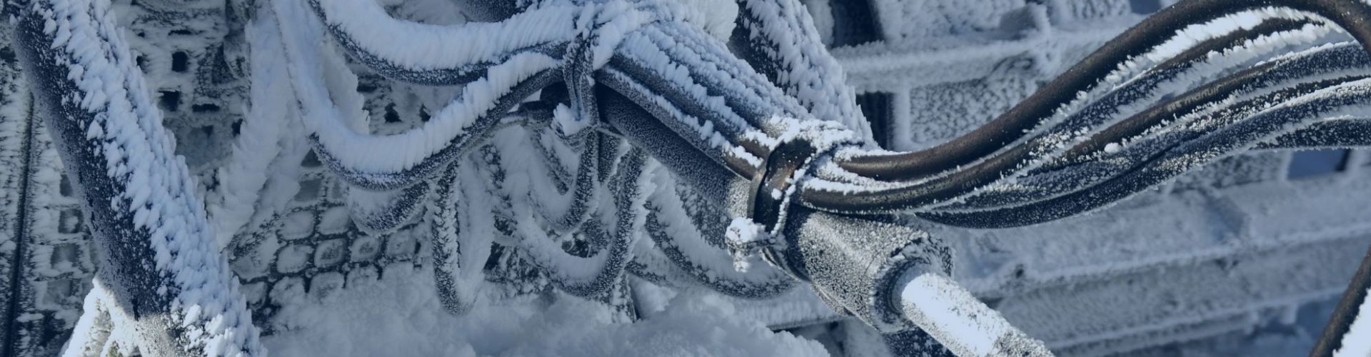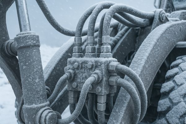
Choosing the wrong hydraulic hose can lead to catastrophic system failure. The information printed on the hose itself is your guide, but it often looks like a secret code.
These markings are a “layline” that identifies the hose’s manufacturer, part number, size (dash size), maximum working pressure, the industry standard it was built to, and its date of manufacture. Understanding this code is essential for safety, maintenance, and performance.
Think of the layline as the hose’s birth certificate and instruction manual combined. Every piece of information printed there is vital. I’ve spoken with countless engineers, maintenance managers, and business owners like Tony, who are meticulous about their components. They know that a misunderstanding of the layline can lead to ordering the wrong replacement part, creating a dangerous mismatch in pressure rating, or unknowingly installing an old hose that is past its service life. At Topa, we believe that an informed customer is a safe and successful customer. Let’s break down this code together, piece by piece, so you can select and replace any hydraulic hose with total confidence.
What Do the Manufacturer’s Name and Part Number Tell You?
You need to replace a failing hose on a critical machine, but you have no idea who made it or what the specific product is. This uncertainty can cause costly delays.
The manufacturer’s name identifies the source and quality standard of the hose, while the part number is the unique code for that specific product. These are your starting points for traceability and accurate reordering.
These first two pieces of information on the layline establish accountability and make your life easier. Seeing a trusted brand name gives you an initial level of confidence, while the part number provides a direct path to a solution. For professional buyers, these aren’t just details; they are the foundation of efficient and reliable maintenance.
The Significance of a Trusted Manufacturer
The brand name printed on the hose is the manufacturer’s signature. It’s a declaration of responsibility for that product’s quality and performance. When you see a reputable name, it implies a whole system of quality control behind the scenes. It means the hose has likely been manufactured in an ISO-certified facility, subjected to rigorous batch testing for pressure and impulse cycles, and is backed by a warranty and technical support. A generic, unbranded hose offers none of these assurances. You have no idea about its material quality, its construction integrity, or how it was tested. Choosing a hose from a known manufacturer like Topa means you are investing in a product with documented performance and a team you can contact if you have questions or need support. It’s the first step in risk management.
Why the Part Number is Your Key to Precision
The part number is the hose’s unique identifier. While the brand name tells you who made it, the part number tells you what it is, with complete precision. When you need to replace a hose, this number eliminates all guesswork. You don’t have to measure the old hose (which may have stretched or deformed) or guess its pressure rating. Providing the part number to your supplier allows them to identify the exact product from their catalog instantly. This ensures the replacement hose has the correct inside diameter, the same or better pressure rating, the correct construction standard, and the right material composition. This simple code is the key to a fast, error-free replacement process, saving valuable time and preventing the installation of an incorrect part that could compromise your system’s performance and safety.
How Do You Interpret the Hose Size or Dash Size?
Using a hose with the wrong diameter can starve your system of fluid or create excessive flow restrictions. This is a common and expensive mistake that hurts machine performance.
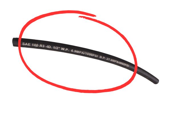
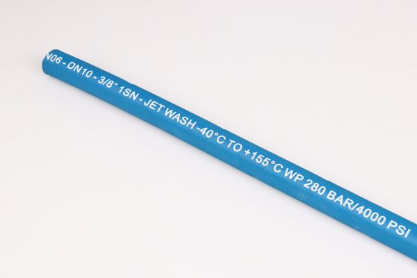
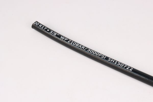
Hose size is shown by a dash number (e.g., -08, -12). This number directly represents the hose’s Inside Diameter (I.D.) in sixteenths of an inch. A -08 hose has an I.D. of 8/16″, or 1/2″.
The dash size is a universal language in the hydraulics industry. It provides a simple, standardized way to talk about the most important dimension of a hose: its inside diameter (I.D.). This dimension dictates fluid velocity and flow rate, which are fundamental to the machine’s power and efficiency.
The Dangers of Undersizing a Hose
Choosing a hose with a smaller I.D. than the system was designed for is a critical error. To push the same volume of fluid through a smaller opening, the fluid must speed up. This dramatic increase in fluid velocity causes several problems. First, it creates turbulence, which leads to inefficient flow and energy loss in the form of heat. An overheating hydraulic system is a common symptom of undersized lines. Second, this high velocity causes a significant pressure drop along the length of the hose, meaning the actuator at the end of the line receives less force than intended, resulting in weak and sluggish machine performance. Finally, extreme fluid velocity can even erode the inner tube of the hose over time, leading to premature failure.
The Inefficiencies of Oversizing a Hose
While less dangerous than undersizing, using a hose that is too large is also problematic. A larger hose holds a greater volume of oil, adding significant weight and cost to the machine—both in the hose itself and the extra fluid required to fill the system. More importantly, it can make the system’s response feel slow and spongy. The lower fluid velocity in an oversized hose means it takes longer for pressure changes from the pump to reach the actuator. This delayed reaction can be a significant issue in applications requiring precise control. The goal is to follow the original designer’s specifications precisely. They chose a specific dash size to perfectly balance performance, cost, and efficiency.
| Dash Size | Inside Diameter (Inches) | Inside Diameter (mm) |
| -04 | 4/16″ or 1/4″ | 6.4 mm |
| -08 | 8/16″ or 1/2″ | 12.7 mm |
| -12 | 12/16″ or 3/4″ | 19.1 mm |
| -16 | 16/16″ or 1″ | 25.4 mm |
What Do Pressure Ratings Like “W.P.” and “M.A.W.P.” Really Mean?
You see pressure numbers on a hose, but do you know the crucial difference between working pressure and burst pressure? A mix-up could lead to a catastrophic hose rupture.
“W.P.” or “M.A.W.P.” stands for (Maximum Allowable) Working Pressure. This is the maximum continuous pressure the hose can safely handle. It is not the burst pressure, which is typically four times higher.
The working pressure is the most important safety specification on the layline. It is the absolute limit for the system’s normal operating pressure, a limit determined through extensive testing and conservative safety factors. Confusing it with burst pressure is a beginner’s mistake with potentially devastating consequences.
Deconstructing the 4:1 Safety Factor
Nearly all international hydraulic standards mandate a 4:1 safety factor. This means a hose with a 3,000 PSI working pressure must withstand a minimum of 12,000 PSI in a lab test before it bursts. This large margin is not arbitrary; it’s a carefully engineered buffer designed to account for the harsh realities of real-world operation. Hydraulic systems are not static. Hoses are bent, flexed, and exposed to external abrasion, all of which can weaken them over their service life. Temperature fluctuations also affect the hose materials. The 4:1 safety factor ensures that even as the hose ages and endures operational stresses, it remains safely above the system’s working pressure. It is the buffer that keeps a working system from becoming a failing system.
Understanding Dynamic Pressure Spikes
The safety factor also exists to absorb pressure spikes, also known as hydraulic shock or pressure transients. In a dynamic system, the pressure is not constant. When a valve closes suddenly or a heavy load is abruptly stopped, the momentum of the moving oil creates a pressure wave that can spike to levels far higher than the system’s relief valve setting. These spikes are instantaneous and can be double or triple the normal working pressure. The hose’s 4:1 safety margin is designed to contain these violent but brief events without rupturing, ensuring the integrity of the system and the safety of everyone around it. Never select a hose whose working pressure is merely “close” to your system’s pressure; it must be equal to or greater than the maximum setting.
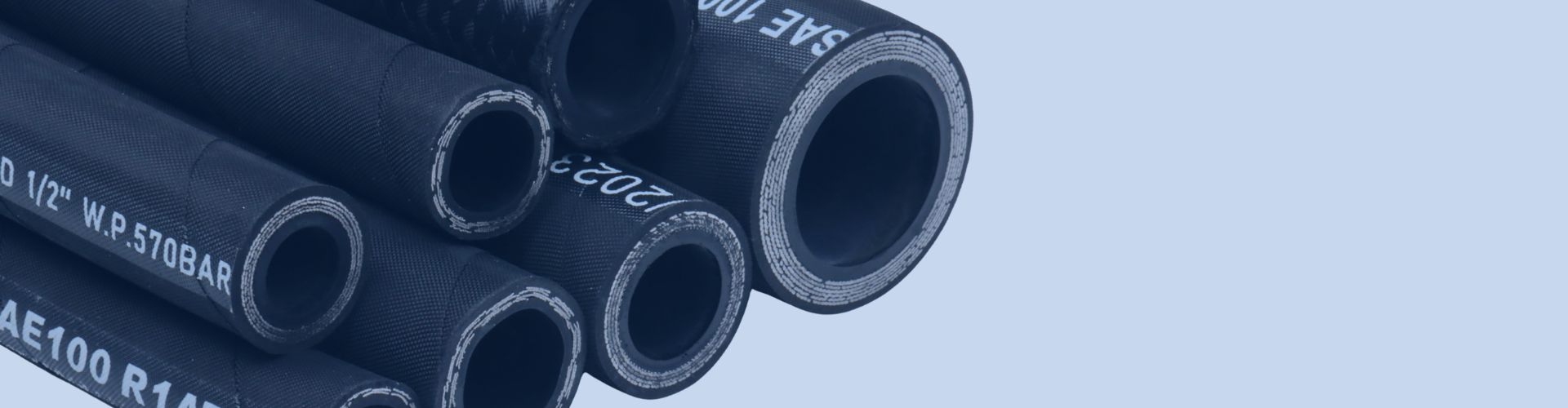
How Do Standards like EN 857 or SAE 100R Affect Your Choice?
You see codes like “SAE 100R2AT” or “EN 857 2SC” on a hose and they look like meaningless gibberish. Choosing the wrong standard can result in a hose that doesn’t fit, perform, or bend as expected.
These codes refer to international standards (SAE – Society of Automotive Engineers; EN – European Norm) that define a hose’s construction, dimensions, pressure rating, and performance characteristics, ensuring interchangeability between different manufacturers.
These standards are the universal language of the hydraulics industry. They guarantee that a hose meeting a specific standard will deliver a predictable level of performance, regardless of who manufactured it. This allows you to source components globally with confidence. The most important distinction in these standards is often the type of wire reinforcement used.
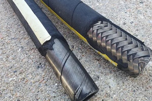
Braided Hose Construction (e.g., 1SN, 2SC)
Braided hose is constructed with one or two layers of high-tensile steel wire braided over the inner tube. This construction method provides excellent flexibility and a relatively tight bend radius. A single-wire braid (like EN 853 1SN or SAE 100R1AT) is suitable for medium-pressure lines. A two-wire braid (like EN 853 2SN, SAE 100R2AT, or the compact EN 857 2SC) offers significantly higher pressure ratings. The “Compact” (SC) versions are a popular choice for mobile equipment because they provide a two-wire pressure rating in a more flexible package with a smaller outside diameter, making it easier to route through tight spaces. Braided hoses are the workhorse for most mobile and industrial hydraulic applications.
Spiral Hose Construction (e.g., 4SP, 4SH)
For very high-pressure and high-impulse applications, spiral hose is the standard. Instead of braiding the wires, four or six layers of high-tensile steel wire are wound spirally around the inner tube. This construction provides superior strength and resistance to the constant flexing caused by high-pressure cycles (impulses). Standards like EN 856 4SP (four-spiral for medium-high pressure) and 4SH (four-spiral extra-high pressure) are common on heavy construction equipment, large industrial presses, and hydrostatic drives. The trade-off for this immense strength is reduced flexibility; spiral hoses have a larger bend radius and are stiffer than braided hoses. The application’s pressure and impulse demands dictate whether a braid or spiral hose is the right choice.
Why is the Date of Manufacture So Important to Check?
A “brand new” hose fails unexpectedly soon after installation. You find out it was sitting on a distributor’s shelf for ten years, its rubber components silently degrading the entire time.
The date of manufacture, often shown as a quarter and year (e.g., “2Q22” for the second quarter of 2022), indicates the hose’s age. Rubber degrades over time, so this date is critical for determining the hose’s remaining shelf life and expected service life.
This is one of the most frequently overlooked details on the layline, yet it is critically tied to safety and reliability. Unlike a solid steel fitting, a hose is a composite product with elastomeric components that have a finite life. Ignoring its age is a significant risk. To properly assess this risk, it’s important to understand the difference between shelf life and service life.
Understanding Shelf Life
Shelf life refers to the period a hose can be properly stored before it is assembled and put into service. Even while sitting on a shelf, the rubber compounds in the hose slowly age due to exposure to oxygen, ozone, humidity, and temperature. SAE Standard J1273 recommends that a hose should not be placed into service if more than 10 years (40 quarters) have passed since its date of manufacture. A good supplier, like Topa, manages inventory using a “first-in, first-out” (FIFO) system to ensure customers receive hoses with the maximum possible shelf life remaining. Proper storage in a cool, dark, dry place is also essential to preserving the hose during this period.
Defining Service Life
Service life begins the moment the hose assembly is installed and pressurized. This is the hose’s working lifespan, and it is always shorter than its shelf life. Service life is highly unpredictable and depends entirely on the application’s severity. Factors that drastically reduce service life include high-impulse pressure cycles, operation near the hose’s maximum temperature limit, routing with tight bends, constant flexing and movement, and external abrasion. A hose in an easy, static application might last for years, while an identical hose on a highly dynamic excavator arm might need to be replaced in a fraction of that time. The key takeaway is that the date of manufacture is your starting point for a finite resource.
What Do Special Markings like “Flame Resistant” or “MSHA” Mean?
A hydraulic line near a hot engine ruptures, and the standard hose cover catches fire. This adds fuel to the flames, turning a manageable problem into a much more dangerous situation.
Special markings indicate that a hose is approved for specific, hazardous environments. “Flame Resistant” means the cover resists ignition, while “MSHA” signifies formal approval for the extreme demands of underground mining applications.
These markings are not marketing terms; they represent crucial safety certifications that have been earned through rigorous, standardized testing. Using a standard hose in an environment that requires a certified one is a violation of safety protocols and can have severe consequences. Always match the hose’s certified properties to the known hazards of its operating environment.
Hazardous Environments: The Need for Flame Resistance
A “Flame Resistant” marking indicates that the outer cover is made from a self-extinguishing compound. When an external flame source is applied and then removed, the hose cover will not continue to burn. This property is vital in any application where there is a risk of fire. This includes steel mills with molten metal, foundries, mobile equipment with hot exhaust components, and welding areas. If a hydraulic line ruptures in these environments, the high-pressure spray of oil can be a significant fuel source. A flame-resistant cover helps prevent the hose itself from catching fire and contributing to the blaze, providing a critical window of time to address the situation safely.
Extreme Demands: The MSHA Standard
The “MSHA” (Mine Safety and Health Administration) marking is one of the most important safety ratings in the industry. It signifies that the hose is approved for use in the incredibly hazardous environment of underground mines. An MSHA-rated hose cover must be exceptionally flame-resistant to a degree far beyond the standard FR rating. More importantly, it must also be tested for electrical conductivity. In a coal mine, explosive methane gas and coal dust can be present. A build-up of static electricity from fluid passing through a hose could create a spark and trigger a catastrophic explosion. MSHA-approved hoses are designed to have a specific level of conductivity to safely dissipate this static charge to the ground, eliminating the risk of an incendiary spark.
Conclusion
The layline on a hydraulic hose is its language. Understanding it is crucial for ensuring safety, achieving peak performance, and simplifying maintenance. It empowers you to make informed decisions.