A Glossary of Hydraulic Hose Terms M-Z

A Glossary of Hydraulic Hose Terms: M-Z?

You need to replace a hose, but the specifications seem like a foreign language. Using the wrong component could mean catastrophic failure, dangerous fluid leaks, and extended, costly downtime for your equipment.

This M-Z glossary decodes essential hydraulic hose terminology. It clearly defines concepts from matched systems and MSHA ratings to working pressure, ensuring you have the precise information needed for safe and reliable hose selection.

Matched System to MSHA?

An assembly fails, but the hose supplier blames the fitting supplier, and vice versa. Using components from different manufacturers creates a liability gray area, leaving you with a failed system and no clear recourse.

A “matched system” is the use of hose and fittings from the same manufacturer, ensuring tested compatibility. MSHA is a critical safety rating for flame resistance, required for hoses used in underground mining operations.

ISO Standard Hydraulic Hose

Ensuring Compatibility and Safety

Matched System: This is one of the most important concepts for hydraulic safety and reliability. A matched system means the hose and the fittings (couplings) have been designed, tested, and validated to work together by a single manufacturer. The manufacturer performs extensive impulse testing and burst testing on that specific combination to guarantee that a proper crimp will meet or exceed published performance standards. Mixing a hose from one brand with a fitting from another introduces unknown variables. The “bite” of the fitting’s stem and the compression of the ferrule may not be optimal for that specific hose’s construction, leading to a drastically weakened assembly that is prone to blow-offs. For this reason, we and most other reputable manufacturers will only guarantee the performance of our hose assemblies when our own fittings are used.

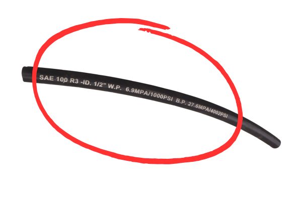
Maximum Working Pressure (MWP): This is the highest pressure that a hose assembly is rated for in continuous service. This is the single most important pressure rating to consider when selecting a hose and should never be exceeded in operation. It is determined by taking the hose’s minimum burst pressure and dividing it by the required safety factor (typically 4:1).

Metric: While dash sizes are based on inches, a significant portion of the global hydraulics market, particularly in Europe and Asia, uses metric measurements (millimeters) and standards, such as DIN and certain EN/ISO specifications for fittings and ports.

MSHA (Mine Safety and Health Administration): This US government agency sets mandatory safety standards for equipment used in underground mining. Hoses with an MSHA rating have a cover that has passed a stringent flame resistance test (CFR 30, Part 18.65), ensuring it will self-extinguish within a set time after an ignition source is removed. This is critical for preventing fires in enclosed, hazardous environments.

Nipple to OD?

A custom hose clamp doesn’t fit the new hose, even though the inner diameter is correct. The outer diameter was not considered during selection, causing delays and forcing a redesign of the mounting hardware.

The nipple is the internal part of a fitting that goes inside the hose. The OD, or Outer Diameter, is the total measurement across the outside of the hose, a critical dimension for clamping and routing.

Hydraulic Hose size Selection

Critical Dimensions and Materials

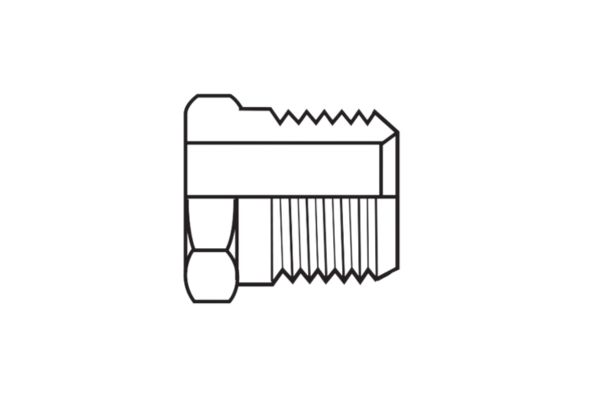
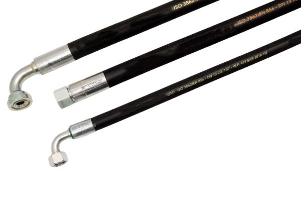
Nipple: Also known as the stem or insert, the nipple is the portion of a hose fitting that is inserted directly into the hose’s inner tube. It typically has serrations or barbs that bite into the tube material to help create a seal and provide holding power once the ferrule is crimped. The nipple’s design is precisely engineered to work with the hose’s inner diameter and tube thickness.

NBR (Nitrile Butadiene Rubber): Often referred to simply as Nitrile, this is one of the most common synthetic elastomers used for the inner tube of hydraulic hoses. Its primary advantage is excellent resistance to standard petroleum-based hydraulic fluids, oils, and greases. It is a cost-effective and reliable choice for the majority of standard hydraulic applications. However, it has poor compatibility with certain synthetic fluids like phosphate esters or water-glycol mixtures.

Nominal Size: This is a general term used to describe the hose’s size, which almost always refers to the Inner Diameter (ID). It is often used interchangeably with “Dash Size.”

OD (Outer Diameter): This is the measurement of the hose from one side of its outer cover to the other. While the ID dictates flow, the OD is a critical dimension for selecting the correct clamps, protective sleeves, and spiral guards. It can also be an indicator of the hose’s construction; for a given ID, a hose with a larger OD typically has more or thicker reinforcement layers and thus a higher pressure rating.

Ozone Resistance to Push-on Hose?

A hose that sits exposed on a piece of farm equipment develops deep surface cracks and fails. It was not rated for ozone and UV exposure, causing the rubber cover to become brittle and disintegrate.

Ozone resistance measures a cover’s ability to withstand environmental cracking. A push-on hose is a low-pressure solution that uses special barbed fittings that do not require crimping or clamps for assembly.

Environmental Factors and Specialized Hoses

Ozone Resistance: Ozone is a gas present in the atmosphere that aggressively attacks the polymer chains in rubber, causing a specific type of degradation known as ozone cracking. This is especially prevalent on hoses that are under tension or bent. A hose cover with poor ozone resistance will become brittle and develop deep cracks when exposed to the environment, compromising its ability to protect the reinforcement. Manufacturers add special anti-ozonant chemicals to their cover compounds to improve this resistance.

Petroleum-Based Fluid: This is the most common category of hydraulic fluid, derived from refined crude oil. Standard hydraulic hoses with NBR (Nitrile) inner tubes are designed primarily for use with these fluids.

Pin-Pricking: This is the process of creating very small perforations in the hose’s outer cover. It is mandatory for hoses used to convey gaseous media (like compressed air or nitrogen) at pressures above 250 PSI. Gas can slowly permeate through the inner tube and become trapped under the cover. Without a path to escape, this trapped gas will form large blisters, causing the cover to separate from the reinforcement and leading to failure. Pin-pricking allows this trapped gas to safely vent to the atmosphere.

Push-on Hose: Also known by trade names like Push-Lok, this is a type of low-pressure hose (typically under 300 PSI) designed for quick and easy field assembly. It uses specially designed fittings with aggressive, deep barbs. The hose is simply pushed onto the fitting by hand, and the barbs grip the inner tube so tightly that no external ferrule or clamp is required. It is ideal for shop air lines, coolant lines, and other low-pressure fluid transfer applications.

Reinforcement to Routing?

A hose on a machine with constant flexing fails repeatedly in the same spot. It was built with a spiral-wire hose, which is too stiff; a more flexible braid hose was the correct choice.

Reinforcement is the internal strength layer of a hose. Routing is the physical path a hose follows during installation, a critical factor in preventing abrasion, kinking, and premature failure.

Hydraulic Hose Assembly install Routing

Strength Layers and Installation Practices

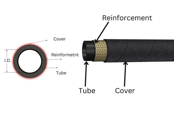
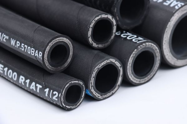
Reinforcement: This is the heart of a hydraulic hose’s strength. It is the layer sandwiched between the inner tube and the outer cover that contains the pressure. There are two primary types:
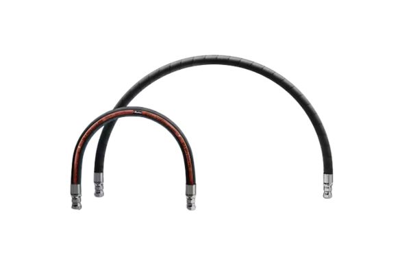
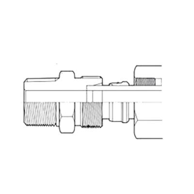
Reusable Fitting: This is a mechanical fitting, usually with a threaded socket and nipple, that can be assembled onto a hose with hand tools and can be disassembled and reused on a new hose. While once common, they have largely been replaced by permanently crimped fittings, which offer far greater reliability and safety in modern high-pressure systems.

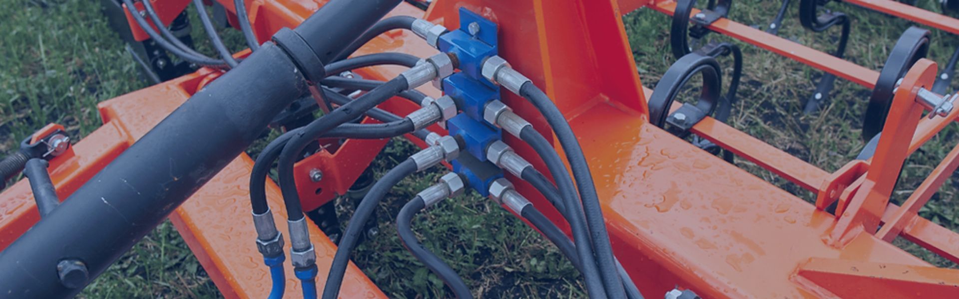
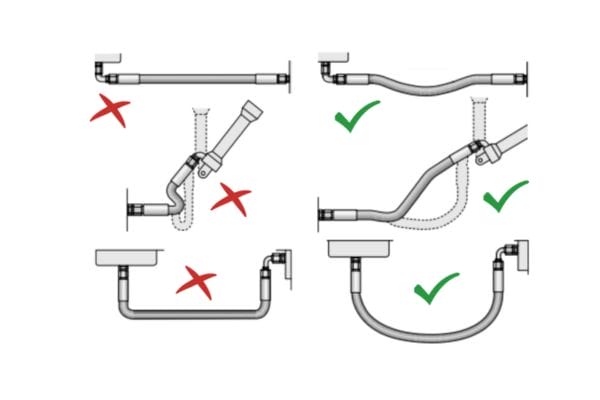
Routing: Proper routing is as important as selecting the correct hose. During installation, the hose’s path must be planned to avoid common failure modes. Hoses should be routed to avoid sharp bends, twisting, pulling, kinking, and abrasion against machine parts or other hoses. Using clamps, brackets, and protective sleeves is essential for a long-lasting, reliable installation.

SAE to Swage?

A hose is specified as “100R2,” but the meaning is unclear. This code represents a specific SAE standard that defines the hose’s construction, pressure rating, and intended application, making it a critical piece of information.

SAE is the standards body that defines most hydraulic hoses. Skive is the removal of the hose cover before crimping, a practice now largely obsolete due to modern no-skive designs. Swage is another term for crimping.

Standards and Assembly Methods

SAE (Society of Automotive Engineers): This US-based organization develops and publishes the “J517” standards that define the vast majority of hydraulic hoses used globally. These standards, such as SAE 100R1, 100R2, or 100R15, provide a universal specification for hose construction, dimensions, pressure rating, and performance. Specifying an SAE standard ensures a certain level of interchangeability and performance, regardless of the manufacturer.

Safety Factor: This is the ratio between a hose’s minimum burst pressure and its maximum working pressure. For dynamic hydraulic applications, the industry-mandated safety factor is 4:1. This means a hose with a 10,000 PSI burst pressure will have a maximum working pressure of 2,500 PSI. This margin provides safety against pressure spikes and gradual fatigue over the hose’s life.

Skive: This refers to the process of removing a portion of the hose’s outer cover (and sometimes the inner tube) before attaching a fitting. While many older hose systems required this, modern “no-skive” hose and fitting technology has made it largely unnecessary. No-skive systems are faster to assemble and have the added benefit of leaving the cover intact under the ferrule, which protects the wire reinforcement from corrosion.

Spiral Reinforcement: As described earlier, this is a construction method where layers of high-tensile steel wire are helically wrapped in parallel to provide strength for very high-pressure applications.

Swage: This is a verb that is synonymous with crimping. To swage a fitting is to use a machine to compress the ferrule and permanently attach it to the hose.

Temperature Range to Working Pressure?

A hose becomes rigid and cracks in a cold-weather application. The selected hose was not rated for the low ambient temperatures, causing the rubber compounds to lose their flexibility and fail prematurely.

Temperature range defines a hose’s operational limits. Working pressure is the maximum continuous pressure a hose is designed to handle safely, the most important specification for any hydraulic application.

Operating Limits and Final Definitions

Temperature Range: Every hose datasheet specifies a temperature range, for example, -40°F to +212°F (-40°C to +100°C). This defines the limits for both the fluid inside the hose (fluid temperature) and the environment outside (ambient temperature). Operating above the maximum temperature will accelerate aging, make the rubber brittle, and can cause the inner tube to harden and crack. Operating below the minimum temperature can cause the hose to become stiff and lose its flexibility, also leading to cracking under flexion. Some fluids or applications may require a de-rating of the maximum temperature.

Thermoplastic Hose: This is a category of hose that uses plastic materials (like nylon, polyester, or polyurethane) instead of rubber. They are known for being lightweight, having excellent chemical resistance, and extremely low volumetric expansion. Standards like SAE 100R7 and 100R8 cover thermoplastic hoses, which are often used in high-pressure hydraulic tools and material handling equipment.

Twist: Twisting a hose along its longitudinal axis during installation is a critical error that drastically reduces its service life. A twisted hose has its reinforcement wires in a state of constant stress. Under pressure, these forces will try to un-twist the hose, which can loosen fittings and cause the wire layers to fatigue and break. The layline should always be used as a guide to ensure it runs straight and is not spiraled after installation.

Vulcanization: This is the chemical process, typically involving heat and pressure, that cures raw rubber into a strong, stable, and elastic material suitable for use in a hose.

Working Pressure (Maximum): This is the ultimate operational guide. It is the highest pressure a hose should see in service and forms the basis for safe and reliable system design. It is what remains after applying a 4:1 safety factor to the hose’s minimum burst pressure.

Conclusion

Mastering this M-Z vocabulary completes your understanding of hydraulic hoses. This knowledge empowers you to select, install, and maintain fluid power systems with maximum safety, efficiency, and reliability.

A Glossary of Hydraulic Hose Terms A-L

A Glossary of Hydraulic Hose Terms: A-L?

Misinterpreting a hydraulic hose specification can lead to system failure. This confusion causes costly downtime, incorrect orders, and potential safety hazards from using the wrong component for the job.

This glossary defines key hydraulic hose terms from A to L. It covers everything from abrasion resistance and aging to bend radius and burst pressure, providing clear definitions to ensure you select the correct hose for your application.

Hydraulic Hose Laylines

Abrasion to Application?

A hose fails long before its pressure rating is reached because its cover was worn away. This external damage exposes the reinforcement, leading to rust, weakness, and an eventual, unexpected rupture.

Understanding terms like abrasion resistance and aging is crucial for hose longevity. Abrasion refers to wear from rubbing, while aging is the material’s degradation over time due to environmental factors like UV light and ozone.

Defining External Threats and Purpose

Abrasion is the mechanical wearing away of the hose’s outer cover through rubbing or friction. In crowded hydraulic systems, hoses often rub against each other or against machine frames. This friction slowly grinds away the protective cover, eventually exposing the steel wire reinforcement. Once exposed, the reinforcement is vulnerable to moisture, which leads to rust and a drastic reduction in the hose’s burst strength. Hose manufacturers combat this by developing special cover compounds with high abrasion resistance, sometimes labeled as “Tough Cover” or “Super Abrasion.” These are tested using standards like ISO 6945, where a hose is run over an abrasive surface under load. For extreme cases, external protection like nylon sleeves or spiral guards can be added.

Aging refers to the degradation of the hose’s rubber compounds over time due to environmental exposure, even if the hose is not in use. The primary culprits are ozone, ultraviolet (UV) radiation from sunlight, and high temperatures. Ozone attacks the polymer chains in rubber, causing small cracks to form, especially when the hose is bent. UV light and heat accelerate this process, making the materials brittle and weak. A hose’s “shelf life” is determined by its resistance to aging.

Application is the single most important factor in hose selection. It defines the entire context of use: the type of equipment (mobile or stationary), the fluid being conveyed, the temperature and pressure ranges, and the external environment. A hose for a static indoor factory press has vastly different requirements than one used on an excavator arm in a quarry.

Bend Radius to Burst Pressure?

A hose kinks and fails prematurely because it was bent too tightly during installation. This restriction starves the system of flow, increases pressure, and leads to catastrophic failure at the bend.

Bend radius defines the minimum curve a hose can handle without damage or flow restriction. Burst pressure is the pressure at which a new hose is expected to rupture, a critical value for determining its safety factor.

Hydraulic Hose Bend Radius Types

Understanding Physical Limits and Strength

Bend Radius (Minimum) is the smallest radius a hose can be bent to without causing damage. It is always measured to the inside curvature of the hose. Violating the minimum bend radius is a common cause of premature hose failure. When a hose is bent too sharply, its reinforcement wires on the outside of the bend are stretched beyond their elastic limit, while the wires on the inside are compressed and can separate from the inner tube. This creates a weak point, restricts fluid flow, and can cause the hose to kink, permanently damaging it. Generally, hoses with more reinforcement layers or higher pressure ratings have a larger (less flexible) minimum bend radius. Datasheets will always specify this value, which must be respected during routing and installation.

Braid refers to a type of reinforcement construction where wires or textile yarns are interwoven in a crisscross pattern around the inner tube. It is the most common type of reinforcement for low-to-medium pressure hydraulic applications. Hoses like SAE 100R1 (one wire braid) and 100R2 (two wire braids) are industry standards. Braid construction generally offers excellent flexibility compared to spiral-wrapped hoses.

Burst Pressure is the pressure at which a new hose assembly is designed to fail or rupture. It is a critical data point determined by destructive testing in a lab. It is crucial to understand that Burst Pressure is NOT the working pressure. Instead, it is used to calculate the hose’s safety margin. The industry standard for dynamic hydraulic systems is a 4:1 safety factor. This means the stated Maximum Working Pressure is only 25% of the minimum burst pressure. This safety margin accounts for pressure spikes, minor fatigue, and other real-world variables.

Compatibility to Cover?

A hydraulic hose swells and becomes mushy, eventually leaking. The wrong fluid was used, chemically attacking the inner tube and causing the entire hose assembly to fail from the inside out.

Compatibility refers to the ability of the hose’s inner tube to resist chemical attack from the fluid it carries. The cover is the hose’s outer layer, designed_ to protect the reinforcement from the external environment.

Hydraulic hose components design Topa

Analyzing Hose Construction and Materials

Compatibility (Chemical) is the ability of the hose’s materials to coexist with the fluid being conveyed without degradation. The most critical component for compatibility is the hose’s inner tube. If the tube material is not compatible with the hydraulic fluid, the fluid will act as a solvent, causing the tube to swell, harden, crack, or delaminate. This breakdown not only leads to leaks but can also send small particles of rubber into the hydraulic system, clogging filters and damaging sensitive components like pumps and valves. Manufacturers provide detailed compatibility charts that cross-reference tube materials with various fluids, from standard petroleum oils to synthetic esters and water-glycol solutions. Checking this chart before selecting a hose is a fundamental step.

Coupling (or Fitting) is the metallic component attached to the end of a hose, allowing it to connect to a port or another assembly. Couplings must be specifically designed for the hose they are being attached to, creating a “matched system” to ensure a reliable, leak-proof connection that can withstand the full working pressure.

Cover is the hose’s outermost layer. Its primary job is to protect the reinforcement layers from the external environment. The cover is formulated to resist abrasion, ozone, UV radiation, chemicals, oil, and sometimes even flames (for applications requiring MSHA approval). The cover provides no pressure-holding capability; its role is purely protective.

Crimp to Cycle Life?

A brand new hose assembly blows off its fitting at half the rated pressure. The connection was crimped incorrectly, creating a weak point that could not withstand the system’s forces, causing a dangerous failure.

Crimping is the process of mechanically attaching a fitting by deforming a metal collar (ferrule). Cycle life is the number of pressure impulse cycles a hose can withstand before showing signs of fatigue failure.

Manufacturing Reliability and Durability

Crimping is the most common method for attaching fittings to hydraulic hoses. The process uses a machine called a crimper, which contains a set of dies. The hose, with the fitting’s stem inserted and a metal collar called a ferrule placed over it, is placed into the crimper. The machine then uses hydraulic force to close the dies, which compress the ferrule down to a precise, predetermined final dimension. This “crimp diameter” is the single most critical parameter for a successful assembly. If the crimp is too loose, the fitting can blow off under pressure. If it is too tight, it can damage the inner tube and reinforcement, creating a weak point. Every manufacturer provides strict crimp specifications for their specific hose and fitting combinations. Adhering to these specifications is essential for creating a safe and reliable hose assembly.

Cure Date is the date the hose was manufactured, or more specifically, vulcanized (cured with heat and pressure). This date, often printed on the layline, is important for managing stock and determining the hose’s “shelf life.” Rubber compounds can age over time, so using a hose that is many years past its cure date may not be advisable, even if it looks new.

Cycle Life is a measure of a hose’s durability and resistance to fatigue. In the lab, a hose is connected to a test rig that subjects it to repeated pressure impulses, rapidly cycling from zero to its maximum working pressure. The number of cycles it endures before failing is its cycle life. This test simulates the dynamic loads experienced in real-world applications. Standards like ISO 18752 classify hoses based on their cycle performance, with ratings from 100,000 cycles for standard-duty hoses to over 1,000,000 cycles for premium, long-life hoses. A higher cycle life rating indicates a more robust hose designed for severe, high-frequency applications.

Dash Size to Durometer?

The wrong size hose was ordered, causing significant project delays. The nominal size description was misunderstood, resulting in a hose that simply does not fit the existing couplings and ports on the machinery.

Dash size is a standard numbering system that denotes the hose’s inner diameter (ID) in sixteenths of an inch. Durometer is a measurement of the hardness of the rubber or plastic materials used in the hose.

Quantifying Physical Properties

Dash Size is the universal industry shorthand for specifying a hose or fitting’s inner diameter (ID). The system is simple: the number after the dash represents the ID in sixteenths of an inch. For example, a -4 (“dash four”) hose has an ID of 4/16″, or 1/4″. A -8 hose has an ID of 8/16″, or 1/2″. This standardized system eliminates confusion and ensures that a -8 hose from one manufacturer will match a -8 fitting from another. Correctly identifying the dash size is the first step in selecting the right hose, as it determines the volume of fluid the hose can carry.

Delamination describes a type of hose failure where the layers separate from one another. This can occur between the inner tube and the first reinforcement layer, between reinforcement layers, or between the reinforcement and the cover. It is often caused by poor manufacturing quality or using a fluid that is chemically incompatible with the inner tube, causing it to break down.

DIN (Deutsches Institut für Normung) is the German Institute for Standardization. Many hydraulic components, particularly metric fittings like the popular DIN bite-type connectors, are manufactured according to DIN standards.

Durometer is the standard measure of a polymer’s hardness. The test uses a device to press a standardized tip into the material and measures the depth of indentation. For flexible materials like hose rubber, the Shore A scale is used. A higher durometer number indicates a harder material. For example, a typical hose cover may have a durometer of 80A. Hardness is often related to other properties; a harder cover material generally offers better abrasion resistance but may be less flexible.

Elastomer to Layline?

A hose fails in the field, but there is no way to identify its specifications. All the markings have worn off, making it impossible to order a correct replacement part quickly and safely.

An elastomer is a polymer with rubber-like elasticity, the general term for hose materials. The layline is the continuous text printed on a hose that provides all its critical identification information.

topa logo hose

Materials Science and Critical Identification

Elastomer is the technical term for a polymer that displays viscosity and elasticity, commonly known as rubber. Nearly all hydraulic hoses utilize synthetic elastomers for the inner tube and outer cover. The specific type of elastomer is chosen based on the hose’s intended application. Common examples include Nitrile (NBR), Neoprene (Chloroprene or CR), and EPDM, each offering a different profile of chemical, temperature, and environmental resistance.

EN (European Norm) is a standard specification adopted by European countries. Similar to ISO and DIN standards, many hydraulic hoses are manufactured to meet EN specifications, such as EN 853 and EN 857, which are harmonized with the popular SAE 100R1 and 100R2 standards.

Ferrule is the engineered metal collar or sleeve that is part of a hose fitting assembly. During crimping, it is the ferrule that is deformed by the crimper dies to secure the fitting onto the hose, creating a permanent, leak-proof connection.

Layline is the single most important source of information on a hydraulic hose. It is the continuous line of text branded or printed along the exterior of the hose. The layline acts as the hose’s specification sheet, providing all the data needed to identify and replace it correctly. A typical layline contains the manufacturer’s name, the hose standard it was built to, the dash size and inner diameter, the maximum working pressure, and often a date code or lot number for traceability. Being able to read and understand the layline is an essential skill for anyone working with hydraulic hoses.

Conclusion

This A-L glossary provides a solid foundation. Understanding these terms is the first step toward building safer, more reliable, and more efficient hydraulic systems for any application.

Bite-Type vs. NPT Fittings Key Differences

Bite-Type vs. NPT Fittings: Key Differences?

A persistent fluid leak from a threaded connection can indicate a fundamental mismatch between the fitting type and the application. This can lead to system inefficiency, costly downtime, and significant safety hazards.

The key difference lies in the sealing mechanism. NPT fittings create a seal on the threads themselves using a taper and sealant. In contrast, bite-type fittings create a mechanical seal by forcing a hardened ferrule to cut into the outer surface of a tube, independent of the threads.

NPTF Thread

How Does an NPT Fitting Create a Seal?

A pipe joint is weeping fluid, despite having been tightened securely. This creates a mess on the factory floor, wastes valuable fluid, and poses a continuous slip hazard for personnel.

An NPT (National Pipe Taper) fitting seals by forcibly wedging its tapered male threads into matching tapered female threads. This interference fit creates an imperfect metal-to-metal seal that requires a thread sealant to fill the helical leak path.

The NPT thread form is one of the oldest and most widely recognized standards in North America, particularly in plumbing and general industrial piping. Its design principle is straightforward: as the male and female fittings are threaded together, the tapered profile causes them to bind, creating friction and a seal. The threads themselves are intended to deform slightly to conform to one another. However, due to standard manufacturing tolerances, a perfect seal is impossible. A continuous spiral gap always exists at the root and crest of the threads. Therefore, the use of a thread sealant—either PTFE tape or a liquid/paste compound—is not optional; it is a mandatory component of the sealing system. The sealant’s job is to fill this microscopic void and prevent fluid from escaping.

The Mechanics and Limitations of a Tapered Thread Seal

The standard NPT thread has a 1.79° taper relative to the fitting’s centerline. When torque is applied, the flanks of the male and female threads are compressed against each other. This high compressive force is what creates the primary seal, but it also introduces significant stress into the material. The reliance on this wedging action is the source of NPT’s primary weaknesses in demanding applications.

Key Issues with the NPT Sealing Method:

What is the Sealing Mechanism of a Bite-Type Fitting?

A hydraulic system is experiencing leaks at the tube connections, particularly after maintenance or in areas with heavy machine vibration. Standard fittings are failing to provide a dependable, long-term seal.

A bite-type fitting creates a robust mechanical seal using three components: a body, a ferrule, and a nut. As the nut is tightened, it forces the hardened ferrule to progressively “bite” into the tube’s outer wall, creating a positive lock.

bite types threads Topa

The bite-type fitting (often known by DIN 2353 or ISO 8434-1 standards) is an engineered solution designed specifically for high-pressure hydraulic tubing. Its genius lies in separating the functions of sealing and thread engagement. The threads on the nut and body serve only one purpose: to provide the clamping force needed for the ferrule to do its job. They do not participate in the sealing process at all. This design isolates the seal from the rotational forces of tightening and creates a connection that is far more resistant to the dynamic pressures and mechanical vibrations common in hydraulic systems. The ferrule acts as a circular cutting tool, creating a permanent, visible groove in the tube that provides both a primary seal and immense holding power.

Dissecting the Ferrule’s Action

The ferrule is the heart of the fitting. During initial assembly, as the nut is tightened to a specific torque or number of turns (e.g., 1.25 turns past hand-tight), the tapered inner surface of the fitting body compresses the ferrule. This forces the ferrule’s hardened leading edge to bite into the softer tube metal. This action creates two distinct seals: one between the front face of the ferrule and the fitting body, and another where the ferrule has cut into the tube. This “bite” provides incredible grip, preventing the tube from pulling out under extreme pressure. After the initial assembly, the ferrule is permanently “set” onto the tube. The fitting can then be disassembled and reassembled multiple times for maintenance, and the seal will remain reliable because it is made by the perfectly formed ferrule seating back into the fitting body, not by re-deforming threads. This reusability and reliability are why bite-type fittings are a global standard for hydraulic equipment.

Which Fitting is Better for High-Pressure Hydraulic Systems?

A hydraulic system operates at pressures exceeding 3,000 PSI and is subject to pressure spikes. Using an inadequate fitting risks a dangerous high-pressure leak, which can cause fluid injection injuries and catastrophic equipment failure.

Bite-type fittings are unequivocally superior for high-pressure hydraulic systems. Their engineered mechanical seal is independent of the threads, providing a more robust, reliable, and vibration-resistant connection designed to handle extreme dynamic pressures.

The fundamental design of an NPT fitting makes it unsuitable for modern high-pressure hydraulics. The seal’s reliance on thread deformation and sealant creates a natural weak point. High pressure can force fluid through the spiral leak path, and pressure spikes can further expand the female port, compromising the seal. The wedging action concentrates stress, making the fitting brittle and prone to fatigue cracking. In contrast, the bite-type fitting is designed from the ground up for this environment. The ferrule’s bite creates a seal that is strengthened by internal pressure; the pressure pushes the tube outward, reinforcing the seal against the ferrule. The body of the fitting contains the pressure cleanly, without imparting dangerous radial stresses onto the port or component it is threaded into.

A Technical Pressure-Rating Comparison

Pressure ratings for fittings are determined by extensive testing under both static and dynamic (impulse) conditions. Bite-type fittings consistently outperform NPT across the board. A typical 1/2″ bite-type fitting in steel might be rated for a working pressure of 5,000 PSI (350 bar) or higher, with a 4:1 safety factor. This means it can withstand a burst pressure of 20,000 PSI. Conversely, a 1/2″ NPT fitting’s pressure rating is highly dependent on the material it’s threaded into and the quality of installation, but it is rarely recommended for service above 3,000 PSI in any dynamic system. The key differentiating factor is performance under impulse and vibration. The bite-type’s positive-lock seal remains stable, while the NPT’s thread-based seal can gradually loosen and leak, a phenomenon that is simply unacceptable in mission-critical hydraulic machinery.

How Does Vibration Affect NPT and Bite-Type Fittings?

Equipment subject to heavy vibration, such as mobile construction machinery or industrial press lines, is experiencing recurring leaks at its fluid connections. The fittings are loosening over time, requiring constant re-tightening.

Vibration is a primary enemy of NPT fittings, causing the thread connection to loosen and compromising the sealant. Bite-type fittings are inherently vibration-resistant because the ferrule’s bite creates a positive mechanical lock on the tube.

NPS to NPT

Vibration attacks fittings by creating micromovements. In an NPT connection, these tiny movements can slowly work the wedged threads apart. As the threads loosen, the compression on the sealant is reduced, and a leak path opens. The problem compounds over time, leading to significant leaks and potential fitting failure. Re-tightening provides only a temporary fix, as the root cause—the design’s susceptibility to loosening—is not addressed. For bite-type fittings, the opposite is true. The ferrule’s sharp edge is physically embedded into the tube. This positive lock, held securely by the clamping force of the nut, resists the micromovements caused by vibration. The nut is not under the same kind of wedging stress as an NPT thread, and the seal itself is separate from the threads, so it remains intact even in applications with extreme, continuous vibration.

The Engineering of Vibration Resistance

The resilience of the bite-type fitting comes from how it distributes forces. The clamping force is axial, pulling the ferrule straight into its seat in the body. The ferrule’s bite resists any torsional or axial movement of the tube itself. This creates a preloaded assembly that is stable and rigid. An NPT fitting, however, relies on friction from radial force. Vibration introduces cyclic loading that can overcome this static friction, allowing the threads to “walk” or back off. This is why NPT connections are strictly forbidden in any high-integrity system, such as aerospace, heavy mobile machinery, or high-pressure gas applications. The bite-type design, by creating a permanent, physical alteration to the tube, provides a far more secure and predictable connection that maintains its integrity throughout the service life of the machine, making it the only acceptable choice for equipment that moves, shakes, and operates under dynamic loads.

What Are the Key Differences in Installation and Reusability?

A system was assembled quickly, but now numerous connections are leaking. Maintenance teams are questioning whether the fittings can be reliably disassembled and reassembled without introducing new problems.

Bite-type fittings offer superior reusability and a more predictable installation process. NPT fittings require careful sealant application, have a high risk of installation error, and are not designed for repeated disassembly.

A Step-by-Step Installation Comparison

A direct comparison of the installation workflows reveals the practical advantages of a bite-type system.

When is it Appropriate to Choose NPT Fittings?

Given its limitations, are there any applications where an NPT fitting is still a valid choice? An engineer needs to select the most cost-effective fitting for a low-consequence, static application.

NPT fittings remain a suitable and cost-effective choice for non-critical, static, low-pressure applications. These include general plumbing for water, permanent compressed air distribution lines, and industrial fluid transfer systems.

NPT Thread Teflon tape

While modern hydraulic systems demand more advanced solutions, it is important to recognize the applications where NPT’s legacy design and low unit cost are advantageous. The key determining factors are pressure and dynamism. In a system that is assembled once and then left alone, with low and stable pressure (generally under 500 PSI), NPT can perform adequately. Its wide availability, especially in North America, and the low cost of individual fittings make it an economical choice for infrastructure like factory airlines or water coolant circuits. The risks associated with NPT (leaks from vibration, cracking from pressure spikes) are minimal in these stable, low-consequence environments. The decision to use NPT should always be a conscious one based on a clear understanding of its limitations.

Cost vs. Risk Analysis

The primary driver for choosing NPT is upfront cost. The fittings themselves are mass-produced and generally cheaper than precision-engineered bite-type fittings. However, a true cost analysis must consider the total cost of ownership, which includes potential risks. For a low-pressure water pipe, the cost of a slow drip is negligible. For a high-pressure hydraulic press, the cost of a leak includes lost hydraulic fluid (which is expensive), cleanup costs, potential environmental fines, machine downtime, and, most critically, extreme safety risks. Therefore, while NPT may save a few dollars per fitting initially, choosing it for inappropriate application transfers that cost higher operational risk and potential maintenance expenses. Bite-type fittings represent a higher initial investment in the component itself, but this investment buys reliability, safety, and lower long-term operating costs in any system where performance truly matters.

Conclusion

NPT fittings are for low-pressure, static plumbing, while bite-type fittings provide the only reliable solution for modern, high-pressure, dynamic hydraulic systems. Choosing correctly ensures system integrity, safety, and long-term performance. If you need to purchase bite type and NPT hydraulic fittings, contact Topa and we can customize the most suitable hydraulic fittings for your needs.

Contact Topa

Save 30% on maintenance costs with our easy-install hydraulic fittings. Contact Now!