U.S.100% Tariffs What Hydraulic Distributors Need Now

U.S.100% Tariffs: What Hydraulic Distributors Need Now

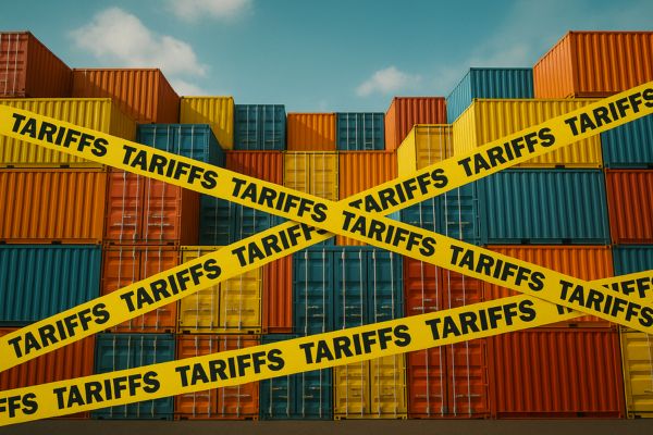
In October 2025, the U.S. government imposed 100% tariffs on Chinese imports — a move that directly impacts the global hydraulic fittings and hose industry.

The Tariff Announcement and Its Immediate Implications

U.S.100% Tariffs

The 100% Tariff Explained

According to **Reuters (2025.10.10)**, the U.S. announced 100% tariffs on Chinese imports to “protect U.S. industry.” This measure marks a significant escalation from prior trade policies, targeting a broad range of industrial goods, including hydraulic fittings and hoses used in manufacturing, construction, and agriculture.

The Scale of Impact

The Financial Times (2025.10.10) reported that more than $150 billion in Chinese goods are affected — the largest escalation since 2018. Hydraulic components, which fall under steel and brass mechanical parts, are within this scope. Immediate consequences include cost surges, disrupted deliveries, and sourcing uncertainty for U.S. buyers.

Inflation and Global Supply Chain Disruption

High Pressure Hose Assembly Failure

Rising Import Costs and Inflation

Bloomberg Economics (2025.10.11) estimates the tariffs will push U.S. import prices up by **7%**, potentially lowering global GDP by 0.3% in 2026. In the hydraulic sector, that price spike translates directly into higher manufacturing and maintenance costs, as most fittings and hoses depend on Chinese machining and plating capabilities.

Supply Chain Fragmentation

Tariffs disrupt established logistics networks. U.S. importers are shifting sourcing toward Vietnam, India, and Mexico, but these countries lack China’s precision standards in machining, zinc-nickel plating, and assembly, creating inconsistencies in thread accuracy and hose crimping performance.

Market Impact Overview

Operational Stress Points

Factories dependent on Chinese raw materials — carbon steel bars, brass billets, and coating chemicals — face shortages. Production delays in fittings and hoses ripple through construction, mining, and machinery industries globally.

Global Reactions and Industry Adjustments

China’s Response and WTO Implications

AP News (2025.10.11) quoted China’s Ministry of Commerce calling the move “a serious violation of WTO principles.” Retaliation has begun, including new port fees on U.S. ships. This adds non-tariff pressure to logistics, potentially increasing freight costs for hose assemblies by up to 20%.

Policy Confirmation and Legal Framework

The USTR (2025.10.11) published the new duty structure under Section 301 Tariff Actions in the *Federal Register*, cementing it as a long-term policy. Legal challenges via WTO may take years, meaning manufacturers must adapt rather than wait for relief.

The Reshaping of the Hydraulic Supply Chain

Navigating New Tariffs in the world

Shifts in Sourcing and Manufacturing

The 100% tariff has triggered a fundamental restructuring of how hydraulic fittings and hoses are sourced, produced, and distributed worldwide. For more than two decades, China has been the backbone of this industry, offering unmatched precision in CNC machining, zinc-nickel plating, automated hose crimping, and large-scale production efficiency. Now, that dominance is being challenged as U.S. buyers and global distributors urgently look for alternatives to avoid the new tariffs.

Southeast Asia—particularly Vietnam, Thailand, and Malaysia—has become the first destination for this redirected demand. These countries are rapidly scaling their manufacturing capacity through joint ventures, technology transfers, and government incentives. However, while their labor costs are competitive, their production ecosystems are still maturing. Critical challenges include inconsistent raw material quality, limited access to high-precision forging equipment, and less-developed testing infrastructure for pressure and salt-spray resistance.

Mexico, driven by its proximity to the U.S., is another strategic hub. Under the USMCA framework, hydraulic components produced or assembled in Mexico may qualify for reduced tariffs, offering U.S. buyers a partial escape route. However, limited domestic steel and brass supply, coupled with higher operating costs, still restrict Mexico’s scalability in this sector.

In contrast, Chinese manufacturers are not standing still. Many are adopting a “China +1” strategy—maintaining their domestic production for Asian and European markets while setting up satellite plants abroad for U.S.-bound orders. This allows them to preserve quality control, maintain brand trust, and reduce dependence on any single trade corridor.

Future Market Structure

How Manufacturers Like Us Will Respond

Domestic Supply Chain Optimization

We are consolidating our partnerships with local raw material suppliers for carbon steel, stainless steel, and brass — ensuring that all bar stock and forging billets meet mechanical and chemical standards before machining begins. By working directly with certified mills and plating specialists inside China, we shorten delivery cycles, improve traceability, and reduce exposure to fluctuating import material costs.

Additionally, we’ve implemented a **tiered supplier evaluation system**, ranking partners based on their delivery accuracy, plating consistency, and dimensional tolerance stability. This data-driven assessment helps us identify weaknesses, provide technical feedback, and co-develop improvements in real time.

Our logistics chain is also undergoing digital optimization. Using ERP integration and smart warehousing, each batch of fittings and hoses can be tracked from forging to final shipment. This ensures zero mix-ups, zero missing items, and complete transparency for customers — even across multiple production lines.

profile projector test Topa

Full Automation for Stability and Precision

The second pillar of our strategy is full automation. In a high-tariff environment, efficiency becomes the most powerful form of cost control. That’s why we are replacing manual operations with **CNC-integrated production, robotic assembly, and automated hose crimping systems**.

Our CNC centers are equipped with real-time dimensional feedback, capable of machining to tolerances below ±0.01 mm. Automated robotic arms handle repetitive assembly tasks such as nut installation, thread cleaning, and O-ring insertion — improving both accuracy and safety.

In the hose assembly section, AI-based crimping machines now adjust pressure and die settings automatically based on hose diameter and material hardness.

Building a Smarter, Stronger Domestic Manufacturing Network

By combining an optimized local supply chain with advanced automation, we are reinforcing our position as a reliable, self-sufficient hydraulic fittings manufacturer.

This strategy not only shields us from external policy risks like tariffs or shipping disruptions but also enhances our long-term competitiveness.

Our focus remains clear — **produce faster, test deeper, and deliver better**.

Quality and Traceability Focus

High tariffs and shifting supply chains have made one truth undeniable: trust is the new currency of global trade. In an environment where component origins may span multiple countries, we are reinforcing our quality assurance system with greater transparency and verifiable data.

We have implemented **ISO 9001 and ISO 14001-compliant traceability protocols**, covering every stage from raw material certification to final inspection. Each hydraulic fitting and hose assembly carries a unique traceability code linking it to its production batch, plating test results, and inspection records.

Our 100% inspection policy ensures that no fitting leaves the factory without passing dimensional, pressure, and plating integrity tests. For corrosion resistance, we maintain continuous **salt-spray testing cycles exceeding 96 hours**, simulating years of real-world exposure to harsh environments.

Ultimately, our response goes beyond survival; it’s about strengthening the foundation for the next era of hydraulic manufacturing. By combining technological precision, flexible supply networks, and uncompromising quality control, we ensure that our fittings and hoses remain reliable, compliant, and competitively positioned — no matter how trade policies evolve.

Long-Term Trends in the Hydraulic Industry

Sustainability and Material Innovation

The 100% tariff has forced both manufacturers and end-users to rethink the long-term sustainability of the hydraulic industry. Rising costs and trade barriers are pushing the market to adopt **longer-lasting materials, cleaner production methods, and smarter product design**.

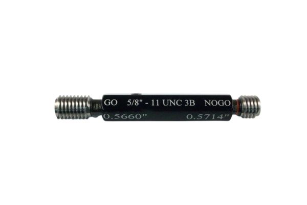
In fittings, stainless steel is emerging as the new standard. Its superior corrosion resistance, strength, and temperature tolerance make it ideal for industries like marine engineering, construction, and oil & gas — sectors where component failure is unacceptable. The 316 stainless series is replacing lower-cost carbon steel, not just for durability but also for lifecycle economy: one stainless steel fitting can outlast three carbon steel fittings in harsh conditions.

Meanwhile, zinc-nickel coatings are becoming the preferred finish for carbon steel fittings. Offering over 720 hours of salt-spray resistance, this coating reduces maintenance frequency and environmental contamination from rust. It also eliminates the use of hexavalent chromium, aligning with RoHS and REACH environmental regulations.

Hydraulic hose manufacturing is following the same trend. The next generation of hoses will feature bio-based or recyclable inner tubes that reduce carbon footprint without sacrificing flexibility or pressure endurance. Advanced polymers like TPU and EPDM blends are being engineered to withstand hydraulic fluids while resisting UV damage and temperature extremes.

The future of hydraulic manufacturing will not be defined by who offers the lowest price, but by who can deliver durability, compliance, and environmental responsibility in a single product line.

Burst Pressure test

Automation and Localization

While sustainability drives material innovation, automation and localization define the next competitive frontier. Western buyers — particularly in the EU and North America — increasingly demand traceable, precision-engineered components from suppliers capable of providing consistent quality documentation.

Automation is the foundation of this reliability. In leading Chinese factories, production is shifting from semi-manual processes to **fully robotic CNC lines, automated deburring, and AI-assisted quality inspection**. Each fitting is measured, tested, and serialized automatically, creating a digital production record that can be accessed by international clients.

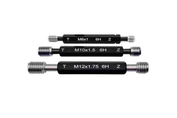
These digitalized systems also enable **predictive maintenance and adaptive machining**, reducing downtime and ensuring every thread and sealing surface meets ISO 8434 and SAE J514 standards. By combining robotics and data analytics, manufacturers achieve both **scalability and consistency**, even across multiple production shifts.

In the long term, the hydraulic supply chain will evolve into a **globally distributed yet digitally unified system**. Core components may still be produced in China — where technical expertise and machining depth remain unmatched — but finishing, customization, and logistics will be decentralized.

For the hydraulic fittings and hose industry, this model blends the best of both worlds: the efficiency of centralized manufacturing with the agility of regional responsiveness. It’s a transformation that promises not only survival under trade pressure but also a stronger, more sustainable foundation for the decades ahead.

Navigating the Next Five Years

Forecast Summary

If the 100% tariff persists for 3–5 years, hydraulic fitting prices in the U.S. may remain **25–40% above pre-tariff levels**, while demand shifts toward premium and locally assembled products. Export-oriented manufacturers must align with regional partners, certification systems, and multi-origin strategies.

Competitive Outlook

In the next five years, the winners will not be those who compete solely on price, but those who combine engineering precision, transparent quality control, and sustainable practices. The hydraulic sector is evolving toward a future where reliability and trust outweigh short-term cost — and those prepared to adapt today will lead tomorrow’s market.

If you are looking for a dependable long-term supplier of hydraulic fittings, hoses, and custom assemblies, contact us today.


FAQ

Why does the 100% U.S. tariff have such a strong effect on hydraulic fittings and hoses?

Because over 60% of global hydraulic fittings and hose assemblies are sourced from China. The tariff directly increases landed costs, disrupts established supply chains, and forces U.S. distributors to find alternative suppliers — often at the expense of quality consistency and delivery speed.

How are Chinese manufacturers responding to the tariff challenges?

Instead of moving production overseas, many are optimizing their domestic supply chains and investing heavily in **full automation**. By upgrading CNC machining, robotic assembly, and digital quality tracking, they are maintaining international standards while avoiding reliance on foreign subcontractors.

What short-term market disruptions are expected after the tariff?

In the first 12–18 months, the industry will face price hikes of **15–30%**, extended lead times. Some smaller distributors may pause imports or shift to partial local assembly to manage cash flow.

How will this situation change the hydraulic industry over the next 3–5 years?

The tariff will accelerate the shift toward **high-end stainless steel fittings, zinc-nickel coatings, and sustainable hoses**. Automation and regional assembly hubs will become standard. The industry will evolve from cost-driven manufacturing to a model built on **traceability, durability, and compliance**.

What are the main advantages of working with automated Chinese manufacturers like Topa?

Automation ensures precise machining tolerances (±0.01 mm), consistent plating, and faster throughput. Combined with domestic supplier control and full traceability, manufacturers like Topa can deliver **stable quality, shorter delivery cycles, and tariff-resilient pricing**.

How can international buyers reduce their risks and maintain stable supply?

By forming long-term partnerships with manufacturers who have **integrated domestic production, verified ISO quality systems, and digital traceability**. Customers who collaborate early on inventory planning and customized packaging solutions can minimize both tariff and logistics risks.

Reference

How to Match 1B, 2B, and 3B Threads for Reliability

How to Match 1B, 2B, and 3B Threads for Reliability?

Are you tired of dealing with persistent hydraulic leaks, but can’t quite pinpoint why your threaded connections loosen or weep fluid? Often, the solution lies in a hidden detail: the thread class.

Understanding thread classes like 1B, 2B, and 3B is crucial for leak prevention in hydraulic systems. Choosing the correct thread class ensures a precise fit, uniform sealing, and long-term reliability in your connections, directly combating the frustrating problem of hydraulic fluid leakage.

What Do 1B, 2B, and 3B Thread Designations Really Mean?

Have you ever seen “1B” or “2B” stamped near a threaded hole and wondered what it signified beyond just a size?

In American National Standard (UN/UNR) threads, designations like 1B, 2B, and 3B define the internal thread’s (hole or nut) tolerance class, with “B” indicating internal threads and the number (1, 2, or 3) indicating the precision or looseness of the fit. Understanding these basic elements is the first step toward creating secure, leak-resistant hydraulic connections.

2B 2A Thread gauge

At its core, a thread designation combines a number and a letter, each carrying a specific meaning crucial for engineering and assembly. These designations are part of the Unified Thread Standard (UTS), which is widely used in the United States and Canada. This system ensures interchangeability and compatibility between different manufactured components.

Unpacking the Code

The Number (1, 2, or 3):

Represents the Tolerance Class (also known as Precision Grade).

This number indicates the permissible range of variation in the thread’s form, pitch, major diameter, and minor diameter. It dictates how tightly or loosely the threads will fit together when assembled with an external thread (like a bolt or a fitting’s male end).

A higher number (e.g., 3) signifies a tighter tolerance and higher precision. This means the manufacturing process must be more controlled, resulting in a thread that deviates very little from its theoretical perfect form. This tighter control creates a connection with minimal clearance.

A lower number (e.g., 1) signifies a looser tolerance and lower precision. This allows for greater variation in manufacturing, resulting in a thread with more clearance. This provides a more forgiving fit, especially in conditions where minor imperfections might exist.

The Letter (B):

Designates Internal Threads.

The capital letter “B” specifically refers to internal threads, which are those machined into a hole (like a hydraulic port on a valve body) or found inside a nut. When you see “B,” you know you are looking at a female thread.

Conversely, for external threads (like those on a bolt, a male hydraulic fitting, or a threaded rod), the letter “A” is used (e.g., 1A, 2A, 3A). These terms “A” and “B” always denote whether the thread is male or female, regardless of the precision level.

How Does Each Thread Class Impact Seal Integrity and Leak Prevention?

Are you struggling with leaks because components feel too loose or too tight? Understanding the inherent fit difference between 1B, 2B, and 3B threads is key to achieving leak-free hydraulic connections.

The core difference among 1B, 2B, and 3B lies in their manufacturing tolerances: 1B offers the loosest fit for easy assembly in non-critical scenarios, 2B provides a balanced, general-purpose fit ideal for most hydraulic applications to prevent leaks, and 3B delivers the tightest, most precise fit for critical, high-performance systems requiring maximum leak prevention and stability.

Here is a breakdown of the core differences and their implications for leak integrity:

Matching Internal and External Threads for a Leak-Proof Connection

Do your hydraulic fittings sometimes feel too loose, too tight, or even jam when you try to assemble them? Improperly matched thread classes are likely the culprit, leading directly to leaks and connection failure.

For a leak-proof and durable hydraulic connection, the internal thread (B class) must be correctly paired with the external thread (A class). This ensures the optimal fit, balancing ease of assembly with the required sealing integrity, and preventing issues like stripping, galling, or eventual leakage that arise from mismatches.

1A 2B 3B UNF Threads

Understanding the “A” Classes (External Threads):

Just as “B” denotes internal threads, “A” denotes external threads (like those on bolts, machine screws, or the male ends of hydraulic fittings). The numbers (1, 2, 3) signify the same tolerance levels as with “B” classes:

Critical Matching Principles for Leak Prevention

The goal is to achieve an appropriate “fit” (loose, free, or tight) that supports the sealing mechanism (whether it’s thread engagement itself, a face seal, or a thread sealant) and dynamic conditions.

1B Internal Thread → Pair with 1A or 2A External Thread

This combination is designed for very easy assembly, even with threads that are slightly damaged, dirty, or have a thick coating (like heavy paint or hot-dip galvanizing).

Leak Implication: The significant clearance in this fit means it offers very limited inherent leak prevention. For hydraulic systems, this combination would almost certainly require additional external sealing methods (like an O-ring on a face, or copious amounts of thread sealant) to prevent weeping.

2B Internal Thread → Pair with 2A External Thread

2B Internal Thread → Pair with 2A External Thread (Most Common, Free Fit):

This is the standard, most versatile, and widely recommended combination for the vast majority of commercial and industrial applications, including hydraulic fittings.

Leak Implication: The “free fit” provides enough clearance for smooth, easy assembly without excessive play. This allows for good thread engagement, ensuring that thread sealants can fill the spaces effectively. It offers a reliable and consistent seal when tightened properly.

3B Internal Thread → Must Pair with 3A External Thread

This combination offers the smallest clearances and results in the tightest possible fit. It is designed for applications where precise alignment, maximum thread engagement, and superior resistance to loosening under extreme conditions are paramount.

Leak Implication: This “tight fit” excels at preventing leaks in critical, high-pressure, or high-vibration hydraulic systems. The minimal clearance offers very effective metal-to-metal contact, enhancing anti-vibration properties and forming an exceptionally robust connection that significantly reduces the potential for fluid escape through the threads.

Critical Warning: Avoid Mismatches!

High-Precision Internal (3B) with Low-Precision External (1A or 2A): This is a critical mismatch. A 3B internal thread has very little allowance. If you try to assemble it with a looser 1A or 2A external thread (which has more manufacturing variation), the larger physical dimensions allowed by the 1A/2A tolerance might interfere with the tight 3B internal thread. This often results in:

By diligently selecting matching A and B thread classes, particularly using the widespread 2A/2B combination for general purpose, or the precise 3A/3B for critical applications, you can effectively manage thread clearances to prevent the common issues that lead to hydraulic leaks.

Why 2B Threads Are the Go-To Standard for Most Hydraulic Fittings

Are you debating which thread class to specify for your everyday hydraulic fittings, worrying about potential leaks or assembly issues? For 95% of applications, the 2B thread class is the undisputed best choice.

The 2B thread class is the ultimate standard for most hydraulic fittings because it delivers an optimal balance of precise fit, ease of assembly, and consistent sealing performance.

2B Thread gauge

The Perfect Compromise for Leak Prevention

The unique characteristics of 2B contribute directly to preventing leaks in everyday scenarios.

When to Rely on 2B

When Do 3B Threads Prevent Leaks in Critical Applications?

The 3B thread class is crucial for preventing leaks in highly critical hydraulic applications where extreme precision and maximum connection stability are absolute necessities. Its minimal clearance provides superior resistance to loosening from intense vibration or pressure fluctuations, making it indispensable for aerospace, military, and precision instrument systems where zero leakage is non-negotiable.

3B Thread gauge

While the 2B thread class serves as an excellent general-purpose solution for leak prevention, there are specific, high-stakes scenarios where its inherent clearances might be insufficient. In these environments, even a minor leak could lead to catastrophic failure, compromise safety, or disrupt highly sensitive operations. For such critical applications, the 3B thread class emerges as the ultimate answer. Its meticulously tight tolerance, when properly matched with a 3A external thread, delivers a level of connection integrity and leak resistance that justifies its higher manufacturing cost and more demanding assembly requirements.

Where 3B Threads Make the Difference for Leak Prevention

The enhanced precision of 3B directly translates to superior leak resistance in challenging conditions.

How Other Standards Tackle Leak Prevention Through Tolerances

Are you only familiar with 1B, 2B, 3B, but work with hydraulic systems from around the world? Different thread standards use their own methods to define precision, all aiming for leak-free connections.

While 1B, 2B, and 3B are unique to American National Unified (UN/UNR) threads, other global standards like Metric and British threads use similar principles of tolerance and fit to prevent leaks. Metric threads use alphanumeric “tolerance grades” (e.g., 6H for internal threads), while British threads have their own legacy classification systems, all designed to ensure precise mating for reliable fluid sealing.

Metric gauge

Metric Threads (ISO Metric Screw Threads)

Metric threads, defined by ISO (International Organization for Standardization), are the most widely used thread standard globally. They employ a more detailed system of “tolerance grades” and “tolerance positions” to define clarity.

British Whitworth Threads (BS 84 / BS 93)

Historically, British Whitworth threads (W or BSW) were used extensively, though they are less common in new designs today, especially in hydraulics, as metric and UN threads dominate. Whitworth threads have a 55-degree flank angle, distinct from the 60-degree angle of UN and Metric threads. They also had their own “fit” classifications.

Pipe Threads (NPT/NPTF, BSPT, BSPP)

Pipe threads are a separate category of threads specifically designed for fluid conveyance and sealing, often differing significantly from parallel (straight) mechanical threads.

Summary Comparison Table

Conclusion

Regardless of the thread standard (UN, Metric, or Pipe threads), diligently matching internal and external threads and adhering to proper installation practices are paramount for achieving and maintaining leak-free hydraulic systems.

Are you ready to permanently solve your hydraulic leak problems by making informed choices about your threaded connections? Contact the Topa team today to discuss your requirements and discover how our precision-engineered hydraulic fittings can enhance the leak integrity and performance of your hydraulic systems.


FAQ

What do 1B, 2B, and 3B thread classes mean?

These thread classes define the tolerance or precision level of internal threads under the Unified Thread Standard. 1B is the loosest fit, 2B is standard for general use, and 3B provides the tightest, most precise fit for critical applications.

Why are thread classes important in hydraulic systems?

Thread classes determine how tightly two threaded components fit together. The correct class ensures proper sealing, prevents leaks, and maintains connection stability under pressure and vibration.

Which thread class is best for hydraulic fittings?

The 2B thread class is the most widely used because it offers a perfect balance between assembly ease, manufacturing cost, and reliable sealing, making it ideal for most hydraulic applications.

What happens if thread classes are mismatched?

Mismatching classes—such as using a 3B internal thread with a 1A or 2A external thread—can cause galling, cross-threading, or incomplete engagement, leading to leaks, connection failure, or permanent thread damage.

When should 3B threads be used?

3B threads are recommended for high-precision or high-pressure environments like aerospace, military, and advanced hydraulic systems where even minor leakage or vibration loosening cannot be tolerated.

How do other thread standards compare to 1B, 2B, and 3B?

Metric and British threads use similar tolerance systems, such as 6H for metric internal threads, to achieve the same goal—ensuring precise fits, secure connections, and leak-free performance in hydraulic systems.

How to Extend the Service Life of Ferrule Fittings

How to Extend the Service Life of Ferrule Fittings?

Leaks and premature failures in piping systems don’t just interrupt operations—they cause costly downtime, safety risks, and unnecessary maintenance expenses. Among the many connection types used in fluid transfer systems, ferrule fittings stand out for their ability to deliver secure, high-pressure, and corrosion-resistant connections.

This article provides a comprehensive guide to improving the reliability of ferrule fittings. From selecting the right materials and optimizing installation techniques to implementing lifecycle maintenance strategies and exploring future innovations, we’ll uncover proven methods to extend service life and prevent leaks.

Material Selection: Building a Long Service Life Foundation

The choice of materials is the most decisive factor in extending the service life of ferrule fittings. Proper material selection improves pressure resistance, corrosion resistance, and temperature tolerance, ensuring reliable performance even in demanding environments.

single ferrule fittings vs double ferrule fittings Topa

Optimizing Body Materials

Ferrule fitting bodies are typically manufactured from stainless steel, duplex steel, or nickel-based alloys. Each material offers unique benefits in terms of mechanical strength, corrosion resistance, and cost efficiency.

Comparison of Common Body Materials for Ferrule Fittings

Matching Seal Element Materials

While the body provides structural strength, the ferrule edge and sealing surface ensure leak-free performance. The correct material for sealing elements can significantly reduce leakage risks.

Comparison of Ferrule Materials

Advantages of PTFE-Coated Ferrules

For applications involving low temperature, vacuum, or sensitive environments, PTFE-coated ferrules provide unique benefits:

Installation Process: Ensuring Reliable Sealing

Even when ferrule fittings are made from high-performance materials, improper installation remains the leading cause of leakage failures. Research shows that more than 60% of connection leaks are directly linked to cutting errors, poor torque control, or vibration loosening. By standardizing installation processes, companies can significantly improve sealing reliability and extend service life.

Standardized Tube Preparation

Cutting Accuracy Using the wrong cutting method creates uneven edges, burrs, or heat damage. Abrasive wheels and flame cutting should be avoided, as they weaken the tube’s surface structure. Instead, dedicated tube cutters maintain precise squareness within ≤0.5 mm and limit burr height to ≤0.1 mm. This ensures the ferrule bites evenly into the tube wall.

Tube Rounding Ovality is a hidden factor that often leads to poor sealing. A rotary tube re-rounder can restore circularity by applying 360° uniform pressure. Test results show that when ovality decreases from 1.2% to 0.3%, leakage probability is reduced by over 90%.

Cleaning Standards Contamination inside the tube can scratch sealing surfaces or obstruct the ferrule’s bite. Using ultrasonic cleaning with trichloroethylene achieves high cleanliness levels. For ferrule fittings, the minimum requirement is NAS1638 Class 5. Studies confirm that if residual particles exceed 50 μm, the risk of leakage is three times higher.

install ferrule fitting

Table: Tube Preparation Standards for Ferrule Fittings

Precise Torque Control

The tightening torque applied to ferrule nuts is a critical factor in achieving leak-free operation. Over-tightening may crack the ferrule or deform the tube, while under-tightening leads to insufficient sealing force. A three-step tightening procedure ensures consistent results:

Vibration Protection Measures

Industrial systems often operate in high-vibration environments, especially in construction machinery, offshore drilling, and aerospace applications. Without vibration protection, ferrule fittings may gradually loosen, leading to micro-leaks or catastrophic failures.

Recommended Solutions:

Table: Vibration Control Solutions for Ferrule Fittings

Maintenance Strategies: Managing the Entire Lifecycle

Ferrule fittings do not fail only because of poor design or materials—lack of systematic maintenance is one of the top causes of premature leakage and downtime. A lifecycle approach that combines preventive maintenance, smart monitoring, and structured failure analysis ensures maximum reliability and long service life.

Risk-Based Maintenance (RBM)

Risk-Based Maintenance (RBM) tailors inspection and replacement intervals to the severity of operating conditions. This avoids both under-maintenance (leading to leaks) and over-maintenance (wasting resources).

RBMMaintenance Intervals for Ferrule Fittings

Intelligent Monitoring

With the rise of IoT (Internet of Things) monitoring systems, real-time data can prevent small issues from becoming costly failures. By tracking key operating parameters, operators can detect early signs of ferrule fitting degradation.

Table: Intelligent Monitoring Parameters for Ferrule Fittings

Failure Mode and Effects Analysis (FMEA)

A structured FMEA approach identifies the most common failure causes in ferrule fittings and defines targeted countermeasures.

Seal Wear (45%)

Thread Loosening (30%)

Material Corrosion (25%)

  • Cause: Exposure to aggressive media and elevated temperatures.
  • Solution: Apply nickel-phosphorus alloy coating (0.1 mm thick) for advanced electrochemical protection.

Table: Common Failure Modes in Ferrule Fittings and Solutions

Common Leakage Types and Solutions

Even when ferrule fittings are manufactured with premium materials and installed according to standards, leakage can still occur under real-world operating conditions. Understanding the failure mode, root cause, and corrective action is the most effective way to minimize downtime and extend service life.

Static Leakage

Cause:

Static leakage usually occurs when the ferrule does not fully bite into the tube wall during installation. Insufficient tightening or improper alignment prevents the ferrule edge from creating a secure mechanical seal.

Solution:

Reinstall the fitting, ensuring the nut is tightened 1–1.25 full turns beyond finger-tight. This guarantees the ferrule edge penetrates the tube wall adequately, forming a leak-free seal.

Ferrule Fitting Fail repair

Dynamic Leakage

Cause:

Dynamic leakage is typically caused by vibration, pulsation, or thermal cycling in the system. Under such conditions, standard ferrules may gradually loosen, creating micro-gaps that lead to fluid leaks.

Solution:

Install self-locking nuts such as Spiralock, which resist loosening under vibration. Additionally, fit anti-vibration supports or dampers near the connection point to absorb oscillations.

Thread Leakage

Cause:

Thread leakage occurs when the sealing gasket inside the threaded area is damaged, deformed, or degraded due to high pressure or temperature fluctuations. Poor-quality gaskets may also fail prematurely.

Solution:

Replace the gasket with a spiral-wound gasket, which combines metal strength with filler flexibility. Increase torque by 10% to ensure uniform contact pressure across the sealing surface.

Corrosion Leakage

Cause:

When the fitting material is incompatible with the fluid medium or operating environment, corrosion can gradually weaken the sealing surface. For example, 304 stainless steel corrodes quickly in sulfur-rich or chloride-heavy environments.

Solution:

Upgrade to high-alloy materials such as Hastelloy C-276 or Duplex Steel 2205, both of which provide exceptional resistance against acidic and chloride-containing fluids.

Common Leakage Types and Corrective Measures

Future Technology Trends

The ferrule fitting industry is evolving as new materials, surface treatments, and digital technologies reshape performance expectations. Future designs will not only focus on mechanical strength but also on longer service life, self-monitoring capabilities, and adaptability to extreme environments.

Nanocoating Technology

Overview:

Nanocoatings are applied to ferrule surfaces to improve resistance against corrosion, fouling, and microbial contamination. A common solution is titanium dioxide (TiO₂) nanocoating, which provides self-cleaning and antibacterial properties.

Benefits:

Additive Manufacturing (3D Printing)

Overview:

Selective Laser Melting (SLM) and other additive manufacturing techniques allow ferrule fittings to be produced with complex internal flow paths. This eliminates sharp edges and reduces turbulence inside the connection.

Benefits:

Digital Twin Technology

Overview:

Digital twins use 3D models combined with real-time sensor data to simulate how ferrule fittings behave under pressure, vibration, and thermal stress. This allows predictive maintenance and optimized design before physical installation.

Benefits:

Comparison of Emerging Technologies

Conclusion

Ferrule fittings remain one of the most critical components in industrial fluid transfer systems. Their long-term reliability depends on the right combination of material selection, precision installation, and lifecycle maintenance strategies. By applying advanced solutions, companies can extend service life by 3–5 times while reducing leakage rates to less than 0.1%.

At Topa, we provide a full range of high-quality ferrule fittings engineered for demanding applications in oil & gas, chemical processing, power generation, construction, and more. Contact our team for product catalogs, technical support, or customized solutions designed to meet your exact requirements.


FAQ

What are ferrule fittings used for in industrial systems?

Ferrule fittings are used to create secure, leak-free connections in hydraulic and fluid transfer systems. They are widely applied in oil & gas, chemical processing, power generation, and aerospace.

How do I choose the right material for ferrule fittings?

Material selection depends on the operating environment. Stainless steel works well for general use, duplex steel resists chlorides, and Hastelloy C-276 is recommended for highly corrosive acids.

What causes ferrule fittings to leak?

Common causes include improper installation, vibration loosening, damaged gaskets, and material corrosion. More than 60% of leaks are related to cutting or torque errors during assembly.

How can I extend the service life of ferrule fittings?

Use high-performance alloys, ensure proper tube preparation, apply precise torque control, and adopt risk-based maintenance. These measures can extend service life by 3–5 times.

What maintenance practices reduce leakage risk in ferrule fittings?

Implement risk-based maintenance (RBM), monitor pressure, temperature, and vibration using IoT sensors, and perform regular inspections of seals and threads to detect wear early.

What new technologies improve ferrule fitting reliability?

Future solutions include nanocoatings for corrosion resistance, additive manufacturing for optimized flow design, and digital twin models for predictive maintenance

.

How to Flush Hydraulic Pipelines for Maximum Reliability

How to Flush Hydraulic Pipelines for Maximum Reliability?

Is your hydraulic system experiencing premature component wear, sluggish performance, or frequent breakdowns? Contaminated pipelines are often the silent culprit, leading to costly repairs, but a proper flushing process can prevent these issues.

The core method for flushing a hydraulic pipeline involves using an oil pump to circulate fluid from the reservoir through the pipeline, gradually increasing and stabilizing system pressure via a relief or unloading valve in a closed-loop circuit. This process, which may include pressure pulses from an accumulator, effectively dislodges and removes contaminants, crucial for maintaining system cleanliness and reliability.

What is Hydraulic Pipeline Flushing, and Why is it Critical?

Have you ever wondered why your newly installed hydraulic system might still fail prematurely? Ignoring the cleaning process of new or repaired pipelines can introduce hidden contaminants that sabotage performance from day one.

Hydraulic pipeline flushing is the systematic circulation of hydraulic fluid or a specialized flushing fluid through a system’s pipelines at controlled pressures and flow rates to dislodge and remove solid contaminants. It is critical because it prevents premature wear of components, maintains fluid purity, improves system efficiency, and significantly extends the overall lifespan of hydraulic machinery.

dirt Hydraulic Rubber Hoses

Before a hydraulic system begins its operational life, or after any significant maintenance or repair work, the internal surfaces of its pipelines can harbor a surprising amount of debris. This can include residual welding slag, metal shavings from manufacturing, rust particles, sand, or even textile fibers. These seemingly small impurities become abrasive agents when suspended in hydraulic fluid. They act like tiny knives, continuously grinding away at the precision-machined surfaces of pumps, valves, and cylinders, leading to accelerated wear, component malfunction, and ultimately, system failure.

The Purpose of Flushing

The primary goals of hydraulic pipeline flushing are clear and directly impact system performance.

Flushing is not a one-time event for a system’s life. It is often necessary after any major repair or component replacement, especially if the system has been opened to the atmosphere for an extended period, allowing new contaminants to enter.

How Do You Prepare for an Effective Hydraulic Pipeline Flushing Operation?

Feeling overwhelmed by the sheer number of steps before you even start the pump for flushing? Inadequate preparation leads to inefficient flushing, missed contaminants, and repeated efforts, costing precious time and resources.

Preparing for an effective hydraulic pipeline flushing operation involves careful initial system configuration, selecting the appropriate flushing fluid, setting up specialized flushing equipment with filtration and conditioning, and implementing strict safety protocols. These preparatory steps ensure that the flushing process is thorough, efficient, and safe, preventing the reintroduction of contaminants.

chemical pipe system

Initial System Configuration

Setting up the system correctly is the first critical step to ensure contaminants are trapped, not recirculated.

Flushing Fluid Selection

The choice of fluid directly impacts flushing efficiency and system compatibility.

Equipment Setup

The right equipment ensures controlled conditions for thorough cleaning.

Thorough preparation lays the groundwork for a successful and effective hydraulic pipeline flushing operation, setting the stage for a clean and reliable system.

What are the Steps for Building Pressure and Circulating Fluid in Flushing?

Are you unsure about the precise sequence for flushing your pipelines, or worried about damaging components during the process? Improper pressure management and circulation can leave contaminants behind or even cause leaks.

Effectively flushing a hydraulic pipeline involves a three-step process: first, fluid filling and air bleeding at low pressure to ensure the entire system is saturated; second, gradual pressure increase with intermittent holding to check for leaks and confirm integrity; and finally, stabilized pressure circulation in a continuous loop, often in both directions, until contamination levels meet specified standards.

“Taboos” in Hydraulic System Design

Step 1: Fluid Filling and Air Bleeding

This initial phase prepares the system for full circulation by removing air.

Step 2: Gradual Pressure Increase

This phase subtly tests system integrity while gently dislodging particles.

Step 3: Stabilized Pressure Circulation

The main cleaning phase, where contaminants are continuously filtered.

By following these detailed steps, you ensure a hydraulic pipeline that is not just clean, but reliably purged of performance-degrading contaminants, ready for optimal operation.

Why is “Gradual Pressure Increase with Leak Checks” So Important?

Do you ever bypass careful pressure checks to save time, only to encounter catastrophic leaks or system failures later? Skipping critical steps in pressure testing compromises safety and the integrity of your entire hydraulic setup.

“Gradual pressure increase with leak checks” is paramount because it systematically tests the integrity of every connection and component, preventing sudden ruptures or major fluid spills. This step-by-step approach allows for early detection of minor leaks or structural weaknesses under controlled conditions, ensuring safety and confirming that the hydraulic pipeline can withstand operational pressures without catastrophic failure.

The Dangers of Rapid Pressure Surges

Rushing the pressure build-up can have severe, costly consequences.

The Benefits of a Gradual, Monitored Approach

A measured increase in pressure provides crucial advantages for system integrity and safety.

This meticulous approach, requiring patience and attention to detail, fundamentally underpins the safety and long-term reliability of any hydraulic system. It ensures that when the system finally goes into full operation, it does so with every connection verified and every weld tested.

Conclusion

Effectively flushing a hydraulic pipeline is a systematic and critical process, fundamental for ensuring the longevity and reliability of any hydraulic system. From meticulous preparation, controlled pressure application, and continuous circulation to crucial temperature management and final strength testing, each step is designed to eliminate contaminants that can otherwise cripple expensive components.

For reliable hydraulic solutions and components that stand the test of time, partner with Topa. Contact us today to discuss your hydraulic hose needs and ensure your systems operate with unparalleled efficiency and dependability.


FAQ

What is hydraulic pipeline flushing?

Hydraulic pipeline flushing is the process of circulating clean hydraulic or flushing fluid through a system’s pipelines to remove dirt, metal particles, welding slag, and other contaminants before operation. It ensures system reliability and prevents premature wear.

Why is flushing necessary before using a new system?

Even new pipelines contain residues from manufacturing or installation. If not removed, these contaminants can damage pumps, valves, and cylinders, leading to system failure. Flushing cleans the system and ensures long-term performance.

What fluid should be used for flushing?

Most systems use the same hydraulic oil that will later operate in the system to ensure compatibility with seals and materials. In some cases, a special low-viscosity flushing oil with cleaning additives is used.

How do you know when flushing is complete?

Flushing is complete when the oil’s cleanliness level meets the system’s target, often defined by ISO 4406 codes. A particle counter confirms that the contamination has been reduced to acceptable limits.

Why is pressure built up gradually during flushing?

Gradually increasing pressure allows operators to safely test all joints and fittings for leaks. It helps detect weak spots early and prevents sudden pipe bursts or costly oil spills.

How often should hydraulic pipelines be flushed?

Pipelines should be flushed before the first system start-up and after major repairs, component replacements, or long periods of inactivity. This keeps the system clean, efficient, and reliable.

Contact Topa

Save 30% on maintenance costs with our easy-install hydraulic fittings. Contact Now!