What Makes JIC Fittings the Standard in American Hydraulics

What Makes JIC Fittings the Standard in American Hydraulics?

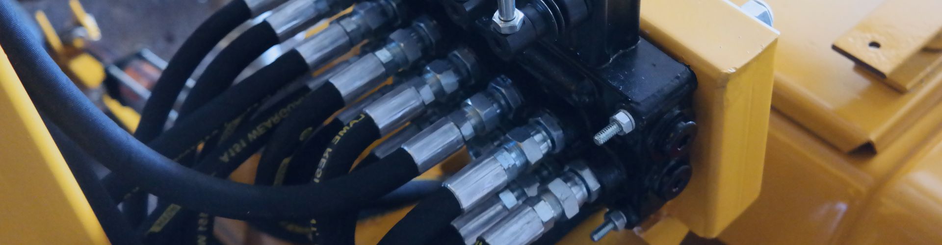
Dealing with hydraulic maintenance on American equipment and getting frustrated by mismatched threads? This incompatibility leads to leaks, costly downtime, and a shelf full of useless fittings.

JIC fittings are the solution. Defined by the SAE J514 standard, their 37° flare design ensures perfect interchangeability across most North American machinery, making them the default choice for reliable, leak-free connections.

What Exactly Defines a JIC Fitting?

You hear the term “JIC” all the time, but what does it actually mean? Ordering the wrong part because of a misunderstanding about the design can stop a project cold.

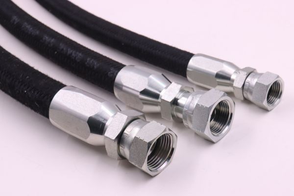
A JIC fitting is defined by its two key features: a 37-degree flared seating surface for a metal-to-metal seal and a straight thread for mechanical clamping force. It is governed by the SAE J514 standard.

JIC 74° Topa

The 37° Flare Sealing Surface

The heart of the JIC fitting is the cone. The male half of the fitting has a 37° cone on its sealing face. The female half has a matching 37° flared seat. When you tighten the nut, these two metal surfaces are forced together. This creates a small, circular line of contact where the metal deforms slightly, creating a positive seal that can hold extremely high pressures. This metal-to-metal design means it can be disconnected and reconnected multiple times without losing its sealing ability, a key feature for reusable fittings.

The Role of Straight Threads

Unlike NPT (National Pipe Taper) fittings, JIC threads are straight, or parallel. They do not form a seal themselves. Their sole purpose is to provide the mechanical strength to connect the male and female halves. Because the threads aren’t being deformed to create a seal, they are less prone to wear and damage from repeated assembly and disassembly. This is a critical distinction that makes JIC hydraulic fittings inherently more reusable and reliable for service and maintenance compared to tapered thread designs.

SAE J514: The Standard of Trust

The Society of Automotive Engineers (SAE) J514 standard is the rulebook for hydraulic JIC fittings. This standard dictates the precise dimensions, tolerances, thread specifications, and performance requirements for every JIC fitting. When we at Topa manufacture our JIC hydraulic fittings, we do so in strict compliance with SAE J514. This guarantees that our fitting will be perfectly interchangeable with any other fitting made to the same standard, regardless of the manufacturer. This global standard is your assurance of compatibility and quality.

Why Is the JIC Standard So Dominant in the USA?

Ever wondered why almost every piece of American-made mobile equipment seems to use JIC? It’s not a coincidence; it’s a legacy of performance and practicality that has made it the default choice.

JIC became the dominant standard in the US due to its military origins, its simplicity, and its widespread availability. This makes it incredibly reliable and easy for technicians to work with in the field.

An and JIC Fittings

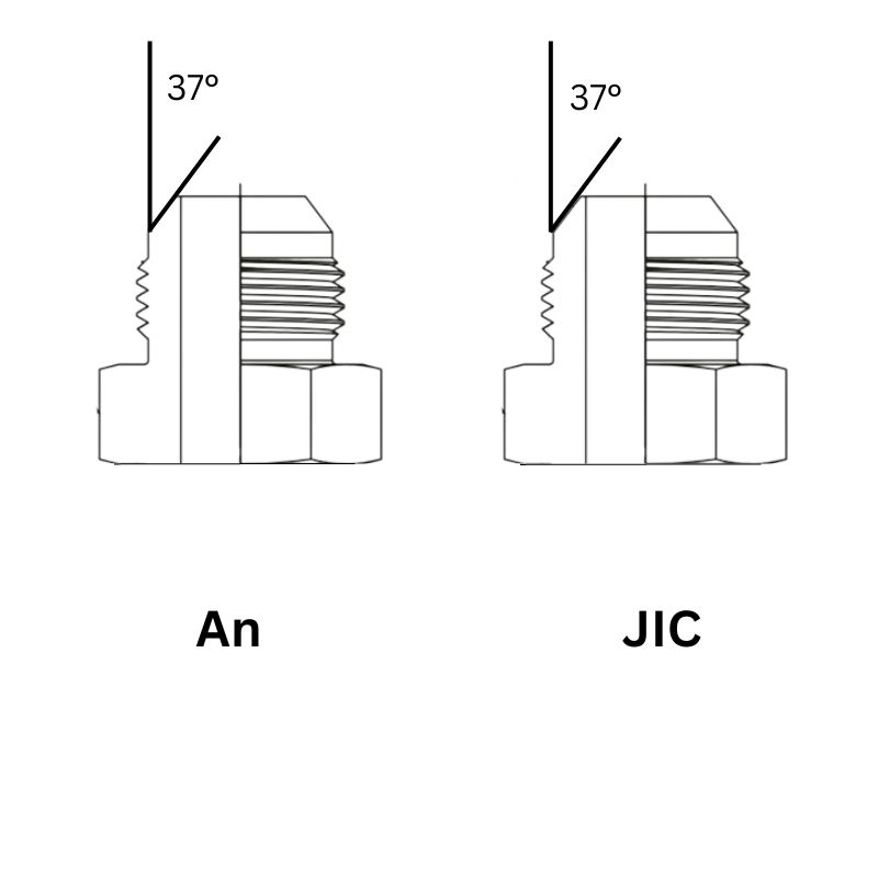
From Military AN to Industrial JIC

The JIC fitting is a direct descendant of the AN (Army-Navy) fitting standard developed during World War II. The AN standard used the same 37° flare but had a higher thread class for military aviation. The industrial version, JIC (Joint Industry Council), adopted the same reliable flare design but with a slightly looser thread tolerance, making it easier and more cost-effective to manufacture for industrial and mobile equipment. This heritage gives it a decades-long track record of performance in the most demanding environments.

Simplicity and Field Serviceability

The main reason for its continued dominance is its simplicity. You don’t need sealant or special tools. Identifying it is straightforward with a caliper and a good eye. Assembling it is easy. Disconnecting and reconnecting it is simple. For a mechanic working on a construction site or a farmer in a field, this simplicity is invaluable. You can make reliable, high-pressure connections quickly with just a couple of wrenches, which is a huge advantage over more complex or single-use fitting types.

Unmatched Availability in North America

Because it is the de-facto standard for most American manufacturers, the JIC fitting is everywhere in the US, Canada, and Mexico. This North American ubiquity means that finding replacement parts, hoses, and adapters is never a problem. For procurement managers and business owners, this simplifies inventory management and reduces the risk of having a machine down while waiting for a rare part to be shipped. It’s the safe, reliable, and accessible choice for any operation using US-built equipment.

How Do You Correctly Identify JIC Threads?

You have a fitting in your hand. Is it JIC, or is it a similar-looking but incompatible 45° flare? Guessing wrong will cause leaks and damaged threads, a costly mistake.

To identify a JIC fitting, you perform a three-step check. First, visually confirm the 37° flare. Second, use calipers to measure the outer diameter of the male thread. Finally, match this measurement against a JIC thread chart.

length measure Topa

Step 1: Visual Inspection for the 37° Flare

The first and most obvious feature to look for is the flared seating surface. A JIC fitting has a distinct 37° cone. This is different from the much steeper 45° flare found on some automotive and refrigeration fittings. If you try to connect a 37° fitting to a 45° fitting, they will only connect on a single, thin line and will never seal properly under pressure. Visually confirming the flare angle is a critical first check.

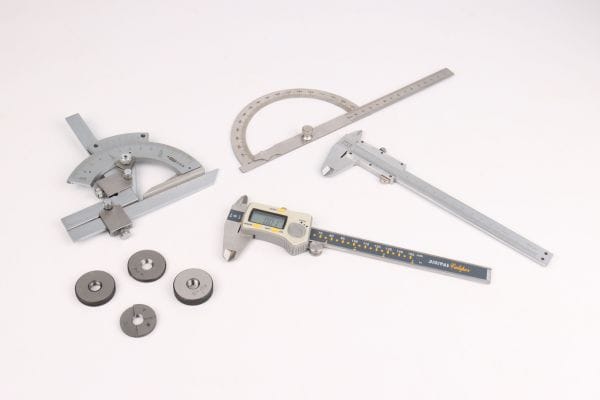
Step 2: Measure the Thread Outer Diameter (O.D.)

Take your digital or dial calipers and measure the outside diameter of the threads on the male fitting. Be as precise as possible. This measurement is the main piece of data you will use to identify the fitting’s dash size. For example, a male thread that measures approximately 9/16 of an inch (or .5625 inches) corresponds to a -06 JIC fitting. Always measure the male thread, as it is a more reliable reference than measuring the inner diameter of the female nut.

Step 3: Match Your Measurement to a Thread Chart

Once you have your measurement, compare it to a standard JIC / SAE J514 thread identification chart. This chart will directly link your thread O.D. measurement to a specific dash size. This removes all guesswork. At Topa, we provide these charts to all our clients to empower them to check their own thread compatibility. It’s an essential tool for any hydraulic professional.

JIC (SAE J514) Identification Chart:

How Do You Assemble a Reusable JIC Fitting?

Your crimper is back at the shop, but you need to make a new hose assembly now. This is precisely what reusable JIC hydraulic fittings were designed for, but how do you do it correctly?

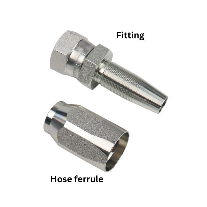
To assemble a reusable JIC fitting, you cleanly cut the hose, screw the outer socket onto the hose, then lubricate and screw the inner nipple into the socket. This simple mechanical process requires only hand tools.

Topa Install and Tighten JIC Hydraulic Fittings

Steps to Install Reusable JIC Hydraulic Fittings

1. Prepare the Hose and Components

2. Install the Socket and Nipple

3. Final Tightening with Wrenches

What Are the Most Common JIC Fitting Mistakes?

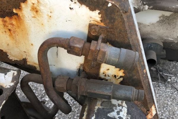
You’ve used a JIC fitting, but it’s still leaking. Before you blame the product, it’s crucial to check for common user errors that can easily cause a perfect fitting to fail.

The most common mistakes are mismatching flare angles (37° vs. 45°), overtightening the nut which cracks the flare, and using tubes with poorly formed flares, all of which will guarantee a leak.

Hydraulic Adapter rust

Mismatched Flare Angles

This is mistake number one. JIC is 37°. Many other systems, especially in HVAC and plumbing, use a 45° flare. They look similar to the untrained eye, and the threads may even be the same. However, the sealing surfaces will not mate correctly. The connection will only touch on a single edge instead of the whole face of the cone. This creates a high-stress point that will not seal under hydraulic pressure and can easily crack the female flare. Always verify both sides of the connection are 37°.

Overtightening and Under-tightening

More is not always better. The torque on a JIC fitting is only meant to press the two metal faces together. If you overtighten it, you can physically crack the cone on the male fitting or the flare on the female fitting, causing a permanent failure. Conversely, if you under-tighten it, there won’t be enough clamping force to maintain the seal against system pressure and vibration. Using the “flats from wrench resistance” method is the best way to get the torque just right without a torque wrench.

Poor Quality Flares on Tubing

When connecting a JIC nut and sleeve to a hard tube, the quality of the flare you create on the tube is everything. Using a low-quality flaring tool can create flares that are off-center, too thin, or have small cracks in them. Any imperfection on this sealing surface is a potential leak path. Always use a high-quality 37° flaring tool, inspect your flares for a smooth, uniform finish before assembly, and never try to flare a tube that has already been hardened or work-hardened.

Conclusion

JIC fittings are the ideal, reliable standard for US hydraulic systems. By ensuring correct identification, proper assembly, and partnership with a quality supplier, you guarantee perfect compatibility and leak-free performance.

At Topa, we specialize in manufacturing high-quality hydraulic fittings, hoses, quick couplings, and adapters fully compliant with international standards like SAE J514, ISO 8434, and DIN 2353.

Whether you need standard JIC, BSP, NPT, ORFS, or customized solutions, Topa provides fast delivery and competitive prices.

Send us your inquiry today and get a tailored quotation within 24 hours.


FAQ

What makes reusable JIC hydraulic fittings different from other fittings?

Reusable JIC hydraulic fittings use a 37° flare metal-to-metal seal and straight threads, allowing multiple reuses without losing sealing performance.

How do I identify a JIC fitting correctly in the field?

Check for a 37° flare, measure the male thread O.D. with calipers, and match it against a JIC SAE J514 thread chart to confirm compatibility.

Can I connect a 37° JIC fitting to a 45° flare fitting?

No, JIC hydraulic fittings must only connect with 37° flares. Mixing 37° and 45° fittings causes leaks, damaged threads, and potential hydraulic failure.

What are the common mistakes when installing reusable JIC hydraulic fittings?

The main mistakes are mismatched flare angles, overtightening or under-tightening, and using poor-quality tube flares that cannot seal properly.

What tools do I need to assemble a reusable JIC hydraulic fitting?

You only need a hose saw or hacksaw, a vise, hydraulic oil for lubrication, and two wrenches for final tightening—no crimping machine required.

Why are hydraulic JIC fittings so widely used in American hydraulic equipment?

JIC fittings dominate in the US due to their military origins, simplicity, reusability, and wide availability, ensuring reliable leak-free connections.

How to Safely Repair Hydraulic Fittings in the Field

How to Safely Repair Hydraulic Fittings in the Field?

Your machine just blew a hydraulic line, miles from the workshop. Now your entire operation is at a standstill, with downtime costing you money with every passing minute.

The best way to handle a field repair is by using field-attachable (reusable) fittings. These allow you to create a new, permanent hose assembly using only basic hand tools, getting your equipment back up and running quickly and safely.

What Safety Steps Are Absolutely Essential Before Starting?

You see hydraulic fluid spraying and your first instinct is to rush in and fix it. This impulse is dangerous and can lead to severe injection injuries, even from systems that appear powered down.

Before touching anything, the absolute first steps are to lock out the machine’s power, completely relieve all stored pressure in the hydraulic system, and put on your required Personal Protective Equipment (PPE). Safety is not optional.

Metric Bite Type Fittings type

Lockout/Tagout (LOTO) is Non-Negotiable

Lockout/Tagout is a formal safety procedure to ensure dangerous equipment is properly shut off and not started up again before the maintenance is complete.

This prevents anyone from accidentally starting the machine while you are working on it.

Releasing Stored Hydraulic Pressure

Turning off the engine is not enough. Hydraulic systems can store energy in accumulators or even within the lines themselves. To release this pressure, you must work the machine’s hydraulic controls (levers, joysticks, etc.) back and forth several times with the engine **off**. You may hear a ‘hiss’ or see the attachments move slightly as the pressure dissipates. Continue until the controls feel loose and unresponsive.

Essential Personal Protective Equipment (PPE)

Hydraulic fluid is a skin and eye irritant. A high-pressure pinhole leak can inject this fluid through your skin, which is a life-threatening medical emergency.

What Are Your Actual Repair Options in the Field?

You’ve made the area safe, but now you’re faced with a broken fitting. What can you actually do with limited tools to create a reliable seal and stop the leak?

Your most effective option is to replace the failed end with a field-attachable, or “reusable,” fitting. For a very temporary fix on certain hose types, a specialized hose repair clamp may be used to get the machine moved.

Reusable Fitting Components Topa

The Best Solution: Field-Attachable Fittings

These fittings are the gold standard for field repairs. They consist of two pieces: an outer socket and an inner nipple. The repair process is mechanical:

This action creates a secure, high-pressure seal. At Topa, we provide these fittings for many common hose types, and they are designed to match the performance of a factory-crimped assembly when installed correctly.

Temporary Fix: Emergency Clamps

In some situations, you might use a bolt-on emergency clamp. These are heavy-duty devices that surround the damaged section of the hose and are tightened with bolts to clamp down on the leak. It is critical to understand that these are temporary, low-pressure solutions meant only to get a machine moved to a safe location for a proper repair. They are not a permanent fix and should not be used in high-pressure or high-vibration applications for any extended period.

What You Must NEVER Do: Welding

Never, ever attempt to weld a hydraulic fitting or tube. The heat from welding can create a catastrophic failure by weakening the metal. More importantly, residual hydraulic fluid inside the line can vaporize into an explosive gas when heated. An attempt to weld a line can turn it into a pipe bomb. There is no situation where welding a pressurized hydraulic component is safe or acceptable.

What Should Be in Your Emergecy Repair Kit?

An equipment failure is stressful enough. The last thing you need is to realize you don’t have the right parts or tools on hand to perform the repair you know how to do.

A well-stocked emergency kit is your best defense against long downtimes. It should contain a curated selection of fittings, hose, and the basic tools needed to perform a field replacement for your specific equipment.

Fieldattachable fittings Install Tools

We actively help our long-term clients build these kits. A fleet manager for a logistics company in the UAE once ordered a huge variety of fittings from us. I worked with him to analyze his fleet’s most common hose sizes and thread types. Based on that, we pre-packaged small “truck kits” with the essentials. This proactive approach has saved his team countless hours. A prepared engineer is an effective engineer.

The Essential Tools

You don’t need a full workshop, just the basics to get the job done. Keep these in a dedicated, easy-to-grab toolbox.

The Critical Components

These are the parts you will be replacing. Your kit should be tailored to your machinery.

The Supporting Items

These small items make the job cleaner, safer, and more successful.

Identify the Problem

Before attempting any repair, the first step is to identify the exact issue with the hydraulic fitting. Misdiagnosis often leads to wasted time, unnecessary part replacements, or even larger failures. Careful inspection ensures you target the true cause of the problem.

Signs of a Failing Hydraulic Fitting

Hydraulic fittings usually give clear warning signs before a total failure. Watch for the following indicators during operation or inspection:

Fail Hydraulic Quick Coupler Maintenance

Quick Field Inspection Checklist

A simple checklist can help technicians quickly assess the problem without dismantling the entire system.

Replace or Reseat the Fitting

When a hydraulic fitting fails, the choice between a quick fix and a full replacement depends on the severity of the damage and the availability of parts in the field. Acting quickly can minimize downtime, but choosing the wrong repair approach may risk safety or system performance.

Temporary vs Permanent Fix

How to Replace a Damaged Fitting

Follow these steps to safely replace a hydraulic fitting in the field:

Field Tip

If no torque wrench is available in the field, tighten the fitting snugly by hand and apply a quarter to half turn with a wrench. Once back in the workshop, recheck torque with calibrated tools.

Test the Repair

Once the fitting has been replaced or reseated, the repair process is not complete until the connection is tested. Skipping this step can result in undetected leaks, leading to repeat failures or safety hazards. A proper test confirms the integrity of the repair before the equipment is returned to service.

System Pressure Test

Verify Reliability

Preventing Future Hydraulic Fitting Failures

Fixing a leak is only part of the job. To reduce downtime and extend system life, it’s critical to adopt preventive measures. Regular inspections and good installation habits can stop small issues from becoming costly failures.

Reusable Hydraulic Fitting hose assembly

Regular Maintenance Checklist

Include these checks in your weekly or monthly schedule:

Long-Term Practices

Beyond routine checks, build habits that strengthen long-term system reliability:

Why Prevention Matters

Consistent maintenance not only prevents leaks but also lowers overall operating costs. By combining inspections, proper training, and standardization, hydraulic systems remain safer, more reliable, and easier to service in the field.

Conclusion

A field repair is about preparation. With a well-stocked kit, a commitment to safety, and knowledge of reusable fittings, you can turn a crisis into a routine, manageable task. At Topa, we supply high-quality Field attachable hydraulic fittings, hoses, and couplings with fast delivery and competitive prices. Send us your inquiry today—our engineering team will provide the best solution for your system needs.


FAQ

What is the quickest way to stop a leaking hydraulic fitting in the field?

The fastest method is to reseat the fitting or replace the O-ring if available. This is only a temporary fix until a proper replacement can be installed.

Can I reuse old O-rings during a field repair?

No. Old O-rings may be cracked, flattened, or chemically damaged. Always use new seals that match the manufacturer’s specifications.

How tight should I make a hydraulic fitting?

Fittings should be tightened to the manufacturer’s torque specifications. If no torque wrench is available, hand-tighten first, then add a quarter to half turn with a wrench.

How do I test a hydraulic fitting after repair?

Slowly re-pressurize the system, inspect the connection for leaks, wipe with a clean cloth, and run the equipment under normal operating conditions.

What tools should I carry for hydraulic field repairs?

A field kit should include O-rings, spare fittings, a thread gauge, torque wrench, sealant, and clean cloths for wiping and inspection.

How can I prevent hydraulic fittings from failing again?

Regularly inspect hoses and fittings, replace worn seals immediately, torque to spec, keep components clean, and train operators to detect early leaks.

How to Select Hydraulic Fittings in 5 Simple Steps

How to Select Hydraulic Fittings in 5 Simple Steps?

Are you an engineer struggling with hydraulic system leaks or failures? Choosing the wrong hydraulic fitting leads to costly downtime, safety hazards, and wasted resources, a problem that frustrates even the most experienced professionals.

You can prevent over 90% of selection errors by following the five-step STAMP method: Size, Temperature, Application, Media, and Pressure. This systematic approach ensures every aspect of your system is considered, leading to a secure and reliable connection.

Step 1: How Do You Define Your System’s Needs with S.T.A.M.P.?

Are you jumping straight to thread types without first understanding your operating conditions? This common mistake is like building a house without checking the foundation; it’s destined to cause problems later.

S.T.A.M.P. is the industry-standard acronym that forces you to define the fundamentals. It stands for Size, Temperature, Application, Media, and Pressure. Answering these five questions first provides the essential data needed to select a compatible and safe fitting.

STAMPED

S for Size

Size is more than just the thread dimension. It primarily refers to the inside diameter (I.D.) of the hose, which determines the flow rate. fittings are sized using “dash numbers” which represent the I.D. in sixteenths of an inch. For example, a -08 fitting is for a hose with an 8/16″ or 1/2″ I.D. Selecting the wrong size can starve the system of fluid or cause excessive velocity, leading to heat and damage. You must match the fitting size to the hose size and the system’s flow requirements.

T for Temperature

You must consider two temperatures: the ambient temperature of the environment outside the hose and the media temperature of the fluid running through it. Extreme cold can make fitting materials brittle, while extreme heat can degrade seals and hose materials. Most standard carbon steel fittings with Buna-N (Nitrile) seals are rated for -40°F to +212°F (-40°C to +100°C). For more extreme temperatures, you may need stainless steel fittings and specialized seals like Viton or Teflon.

A for Application, M for Media, P for Pressure

These three are closely related. Application covers the physical routing, potential for abrasion, and vibration levels. Media refers to the type of fluid being conveyed. Is it a standard petroleum-based hydraulic oil, or a synthetic fluid, water, or chemical that might require special materials like stainless steel? Finally, Pressure is critical. You must know the system’s maximum working pressure, including any potential spikes or surges. The fitting’s pressure rating must always exceed the system’s maximum working pressure.

Step 2: How Do You Accurately Identify the Thread Type?

Have you ever tried to connect a metric fitting to an inch-based port? The threads might seem to catch, but they will never seal correctly, guaranteeing a leak and damaging both components.

You must accurately identify both the type and size of the thread. Use a pair of calipers to measure the thread diameter and a thread pitch gauge to determine the spacing. This is the only way to ensure you are selecting a mating part that will create a perfect seal.

Identifying Hydraulic Fittings Tools

Tapered vs. Straight Threads

This is the first major division. Tapered threads (like NPT and BSPT) are designed to seal by deforming and creating an interference fit along the threads. They always require a sealant like PTFE tape. Straight threads (like JIC, ORFS, and BSPP) do not seal with the threads. Their function is purely mechanical, providing the clamping force to press two separate sealing surfaces together. This could be a metal cone (JIC) or a soft O-ring (ORFS, BSPP). Mixing these two types is a guaranteed failure.

Identifying Common Thread Standards

Once you know if it’s tapered or straight, you need to identify the specific standard.

The Identification Process

Step 3: Which Material is Right For Your Application?

Are you using standard carbon steel fittings in a saltwater environment? Choosing a material that isn’t compatible with your application can lead to rapid corrosion, contamination of the hydraulic fluid, and sudden failure.

The material choice depends directly on your STAMP analysis. For most standard hydraulic systems, zinc-plated carbon steel is the cost-effective workhorse. For corrosive environments or specific media, you must upgrade to stainless steel or brass.

JIC Fitting material

Carbon Steel – The Industry Standard

Carbon steel is the most common material for hydraulic fittings due to its excellent strength and relatively low cost. To protect it from rust, it is almost always coated, typically with an electroplated zinc or a zinc-nickel alloy. This coating provides good resistance to corrosion in most general-purpose applications. It’s the go-to choice for construction, agriculture, and manufacturing machinery where the fittings aren’t exposed to extreme chemicals or saltwater. Its high pressure-holding capability makes it suitable for the vast majority of hydraulic systems.

Stainless Steel – For Corrosion and Purity

When corrosion resistance is the primary concern, stainless steel is the answer. There are two common grades used for fittings:

Brass – For Specific Applications

Brass is an alloy of copper and zinc. It offers very good corrosion resistance and is softer than steel, which allows it to seal well in some low-pressure applications. However, its primary use in hydraulics is where there is a risk of sparking. Because it’s a non-sparking material, it’s often specified for use in explosive environments like underground mines or certain gas facilities. It has a lower pressure rating than steel, so it is typically limited to lower-pressure pneumatic or hydraulic lines.

Step 4: What Fitting Shape Do You Need for Routing?

Are you using multiple straight fittings and adapters to make a 90-degree turn? Every additional connection point you create is another potential leak path and adds unnecessary cost and complexity to your system.

Select a fitting shape that routes the hose directly from port to port with a gentle bend and minimal stress. Use straight fittings for straight runs, and use 45° or 90° elbow fittings to navigate corners and obstacles cleanly.

push locks types

Straight Fittings

Straight fittings are the most common shape. They are used when the hose runs directly away from the port without any immediate turns. They connect a hose to a port, or they can be used to connect two hoses together (as a union). While they are the simplest configuration, you must ensure that there is enough room for the hose to make a natural bend without kinking near the fitting. A kink not only restricts flow but also puts immense stress on the hose’s reinforcement, leading to premature failure.

Angled Fittings (Elbows)

Elbow fittings are essential for efficient plumbing. They are most commonly available in 90° and 45° angles. Using an elbow allows the hose to exit the port at an angle, eliminating the need for a sharp bend. This is critical in tight spaces found on mobile equipment. It reduces the total length of hose required and, most importantly, prevents stress and potential abrasion points that occur when a hose is forced into a tight radius. Always choose an elbow over a straight fitting if the hose needs to make an immediate turn.

Branch Fittings (Tees and Crosses)

Tees and crosses are used to split a single hydraulic line into two or more lines or to combine multiple lines into one. A tee fitting has one inlet and two outlets (or vice-versa), while a cross has one inlet and three outlets. These are vital for creating more complex circuits where you need to send fluid to multiple actuators from a single pump, or where you need to install gauges and sensors into a line. Using a single tee is far more reliable and professional than trying to stack multiple adapters to achieve the same result.

Step 5: How Do You Verify the Supplier and Standards?

You’ve found a fitting that looks right online for a very low price. But how do you know if it meets international quality standards, or if the supplier will still be there to support you tomorrow?

Always choose a supplier who can prove their products conform to international standards like SAE, ISO, and DIN. Furthermore, evaluate the supplier on their service, responsiveness, and technical support, not just the price. A reliable partner is worth more than a cheap part.

SAE EN ISO

Why International Standards (SAE, ISO, DIN) Matter

International standards are a guarantee of interchangeability and performance. When a fitting is made to an SAE J514 (JIC) or ISO 8434-2 standard, you can be confident that it will properly connect with any other fitting made to that same standard, anywhere in the world. These standards dictate everything from thread dimensions and tolerances to burst pressure requirements and material composition. A fitting without a clear standard is a complete gamble. Always demand that your supplier specify the standards their products meet.

Evaluating a Supplier’s True Value

A low price is tempting, but it can hide many costs. A truly valuable supplier offers more.

The Hidden Costs of a Bad Supplier

Choosing a poor supplier can be disastrous. You may receive parts that fail prematurely, causing expensive equipment damage and dangerous situations. You could face production delays because of late shipments or incorrect parts. If a part fails in your customer’s machine, it damages your own reputation. The money you saved on a cheap fitting is quickly lost to rework, downtime, and lost business. Investing in a quality part from a reputable supplier is an investment in peace of mind.

Conclusion

Selecting the right hydraulic fitting is easy with the 5-step method: use S.T.A.M.P., identify threads, choose your material and shape, and verify your supplier. This secures a leak-free, reliable system.

At Topa, we provide reliable hydraulic fittings, hoses, and adapters that meet SAE, ISO, and DIN standards. With fast response, wide product range, and strict quality control, we ensure leak-free and durable connections for your systems. Contact us today to request a quote!


FAQ

What is the STAMP method in hydraulic fitting selection?

STAMP (Size, Temperature, Application, Media, Pressure) is a systematic approach that ensures fittings are chosen based on actual system conditions for safe and reliable performance.

Why does thread identification matter in hydraulic fittings?

Correctly identifying thread type and size prevents mismatches like BSP vs NPT, which can cause leaks, damage components, and compromise system safety.

Which material is best for hydraulic fittings?

Carbon steel suits general use, stainless steel is ideal for corrosion environments like marine or chemical, and brass is used in low-pressure or spark-free conditions.

How do I select the correct fitting shape?

Choose straight fittings for direct runs, elbows for bends, and tees or crosses for branching lines; reducing adapters lowers leak risks and simplifies routing.

Why should I only buy fittings that meet ISO, SAE, or DIN standards?

Certified standards guarantee proper dimensions, sealing, and pressure ratings, ensuring fittings are interchangeable, durable, and globally compatible.

What are the risks of choosing a low-cost, uncertified supplier?

Cheap suppliers may deliver fittings with poor tolerance or weak materials, leading to leaks, downtime, safety hazards, and higher long-term costs.

How to Choose Between Braided and Spiral Hydraulic Hoses

How to Choose Between Braided and Spiral Hydraulic Hoses?

Hydraulic hoses are vital for transferring fluid under pressure. Two main types dominate the market: braided hydraulic hoses and spiral hydraulic hoses. Each type has unique strengths, structures, and applications. Understanding these differences helps buyers and engineers choose the right hose for their systems.

Understanding Braided Hydraulic Hoses

What Is a Braided Hydraulic Hose?

A braided hydraulic hose is reinforced with high-tensile steel wires woven in a crisscross pattern. This structure resembles a plait, providing strength and flexibility. Most braided hoses have one or two wire layers, while special types may include three. These hoses are categorized under standards such as SAE 100R1 and SAE 100R2, making them widely accepted in industrial and mobile hydraulic systems.

Structure of Braided Hoses

Braided hoses use overlapping steel wires arranged in alternating directions. This mesh distributes stress evenly and resists pressure. Unlike spiral hoses, the end view of a braided hose looks disorganized, with steel bundles grouped together instead of clear rings. This design supports flexibility, making braided hoses easy to route through tight hydraulic assemblies without sacrificing strength.

SAE 100R1 hose hydraulic Topa

Applications of Braided Hoses

Advantages of Braided Hoses

Limitations of Braided Hoses

Understanding Spiral Hydraulic Hoses

What Is a Spiral Hydraulic Hose?

A spiral hydraulic hose is reinforced with several layers of high-strength steel wire wound in a helical pattern. Each layer alternates its winding direction to distribute stress evenly. This construction provides exceptional durability and makes spiral hoses suitable for extreme pressure and demanding hydraulic systems. Most spiral hoses have four or six layers, classified under SAE standards such as R12, R13, and R15.

Structure of Spiral Hoses

The wires in spiral hoses are tightly wound in a continuous helix. One layer spirals clockwise, while the next spirals counter-clockwise, ensuring balanced force distribution. When viewed from the end, the reinforcement appears like tree rings, with clear, uniform layers. This structured pattern gives spiral hoses superior strength and consistent performance under repeated impulses.

SAE 4SH hydraulic hoses Topa

Applications of Spiral Hoses

Advantages of Spiral Hoses

Limitations of Spiral Hoses

Hose Performance and Ratings

Spiral Hose Performance and Ratings

Working pressure range: 42–70 MPa Spiral hoses are engineered for very high working pressures. Depending on the series, they can safely handle ranges between 42 MPa and 70 MPa. This makes them suitable for heavy-duty hydraulic circuits in construction and mining equipment.

Impulse cycles: Exceeding 1,000,000 Spiral hydraulic hoses are designed for extreme impulse resistance. Many models can withstand over one million impulse cycles without failure. This durability makes them ideal for hydraulic systems with frequent pressure surges, such as excavators, bulldozers, and drilling rigs, where pulsating loads are constant.

Temperature range: -40°C to +120°C With compatible hydraulic fluids, spiral hoses maintain performance across wide temperature ranges. They function reliably in freezing outdoor environments and in high-heat industrial applications. Special hose covers are also available to resist abrasion, ozone, and higher temperatures if required by the operating environment.

Common standards: SAE and EN certifications Spiral hoses follow international standards to guarantee quality and safety. Typical models include SAE 100R12, SAE 100R13, SAE 100R15, EN 856 4SP, and EN 856 4SH. These certifications define hose structure, pressure ratings, and impulse requirements, ensuring global compatibility and consistent performance.

Hydraulic Hose Spiral Layer vs braid layer

Braided Hose Performance and Ratings

Typical working pressure: up to 40 MPa

Braided hydraulic hoses are generally rated for low to medium pressures, reaching up to 40 MPa depending on hose size and construction. This makes them suitable for return lines, steering systems, and auxiliary circuits in agricultural or light construction machinery.

Impulse resistance: moderate Compared with spiral hoses, braided hoses have lower impulse endurance. They can handle moderate cycling, but frequent or strong pressure surges shorten service life. In impulse-heavy systems such as excavators or drilling rigs, spiral hoses are preferred.

Temperature range: -40°C to +100°C Braided hoses operate reliably in temperatures from -40°C up to +100°C. With specialized materials, some versions can withstand up to +120°C. This makes them effective in outdoor equipment, industrial machinery, and hydraulic return lines exposed to moderate heat. For higher heat, special hose covers are required.

Standards: SAE and EN certifications Common braided hose standards include SAE 100R1, SAE 100R2, EN 853 1SN, and EN 853 2SN. These standards define performance requirements, pressure ratings, and testing methods. Compliance ensures hoses are safe, interchangeable, and globally available, providing reliability for OEMs and maintenance operations.

How to Choose Between Braided and Spiral Hoses

Step 1: Evaluate System Pressure

System pressure is the most critical factor when selecting hydraulic hoses. Braided hoses perform well in medium-pressure circuits, typically under 40 MPa, making them suitable for return lines and steering systems. Spiral hoses, on the other hand, are built for extremely high pressures above 40 MPa and are safer in heavy-duty equipment. Always compare your system’s maximum pressure with the hose’s rated working and burst pressures before choosing.

Step 2: Check Installation Space

Installation space greatly affects hose choice. Braided hydraulic hoses are highly flexible and can bend tightly, which is ideal for tractors, forklifts, or compact hydraulic units. Spiral hoses need more room because of their larger bend radius, making them more suitable for mining machines or cranes with spacious layouts. Forcing spiral hoses into tight spaces may cause kinking or premature wear, so routing must always be planned carefully.

Step 3: Consider Budget

Cost is an important factor for both OEMs and maintenance teams. Braided hoses are affordable and offer good performance in general-purpose applications, reducing upfront expenses. Spiral hoses, while more expensive, deliver a longer service life in high-pressure conditions. This reduces downtime and lowers long-term maintenance costs. Businesses must weigh the balance between initial purchase price and lifecycle cost savings when deciding between braided and spiral hoses.

Step 4: Match with Standards

Choosing a hose that complies with recognized international standards ensures safety and compatibility.

Braided hoses: SAE 100R1, SAE 100R2, EN 853 1SN, EN 853 2SN.

Spiral hoses: SAE 100R12, SAE 100R13, SAE 100R15, EN 856 4SP, EN 856 4SH.

These standards define hose construction, pressure ratings, impulse resistance, and testing methods. Using standardized hoses ensures replacement availability worldwide, prevents compatibility issues, and guarantees reliable performance under specified working conditions.

Step 5: Maintenance Planning

Maintenance requirements vary by hose type. Braided hoses withstand frequent bending but degrade faster under repeated pressure impulses. They should be inspected often for leaks, cracks, or wear. Spiral hoses excel in heavy-duty cycles with continuous high loads and strong impulses. Their longer service life reduces downtime and replacement frequency. Planning maintenance based on hose type ensures system reliability and lowers unexpected hydraulic failures in critical equipment.

Common Problems in Hydraulic Hoses

Issues with Braided Hoses

Burst under high pressure Braided hoses are built for medium pressure, not extreme loads. If system pressure exceeds their rating, the reinforcement can fail suddenly. This results in hose bursts, fluid leakage, equipment shutdown, and even safety hazards. Operators must always check manufacturer data before using braided hoses in demanding systems.

Kinking due to repeated bends While braided hoses are flexible, over-bending or routing them too tightly can cause kinks. Kinking restricts fluid flow, increases turbulence, and puts extra stress on hose walls. Over time, this weakens the hose structure, making it prone to cracking or internal damage. Proper routing and bend radius guidelines help prevent this issue.

Shorter service life in impulse-heavy systems Braided hoses have lower impulse cycle ratings than spiral hoses. In hydraulic systems with frequent pressure spikes, the reinforcement fatigues faster. This leads to shorter service life, more frequent replacements, and higher long-term costs. For equipment exposed to continuous pressure pulsations, spiral hoses are often a better choice.

braided vs spiral hose

Issues with Spiral Hoses

Harder to install in tight spaces Spiral hoses have a larger bend radius, making them less flexible. In machines with compact layouts, installation can be difficult. Forcing a spiral hose into a small space risks twisting or overstressing it, which accelerates wear and reduces performance. Careful system design and routing are necessary.

Heavier weight adds load to connections Spiral hoses contain four to six steel wire layers, which increases weight. This extra weight transfers stress to hose fittings, clamps, and adapters. Over time, the added load may loosen connections, cause fitting leaks, or even damage mounting points. Using proper clamps and support brackets is essential to reduce strain.

Higher replacement cost Spiral hoses are more expensive because of their multi-layer wire construction and advanced durability. While they last longer, the initial purchase price and replacement costs are higher than braided hoses. For companies managing large fleets, this can significantly impact maintenance budgets unless offset by reduced downtime.

Maintenance Tips for Longer Hose Life

Regular Inspections

Hydraulic hoses should be checked routinely for cracks, bulges, abrasion, or fluid leaks. Small surface defects can quickly worsen under pressure. Replace hoses before they completely fail to prevent costly downtime and potential safety risks. Using a scheduled inspection plan helps extend system reliability and reduces unexpected failures.

Correct Installation

Improper installation is a common cause of hose failure. Avoid routing hoses with bends sharper than the minimum bend radius specified by the manufacturer. Prevent twisting during assembly, as torsion stresses the reinforcement wires. Secure hoses with clamps to reduce vibration and movement that could accelerate wear.

Proper Storage

Storage conditions significantly affect hose life. Keep hoses in a dry, cool place away from moisture and extreme heat. Avoid direct sunlight, which degrades rubber covers and weakens flexibility. Protect hoses from chemicals, oils, and solvents that may corrode the outer layer. Correct storage preserves hose performance until installation.

Use Matching Fittings

Always use fittings and adapters designed for the selected hose type and size. Mismatched fittings can cause poor sealing, leaks, and premature failures under pressure. Follow SAE or ISO fitting standards to ensure compatibility. Using original or approved fittings also makes future replacements faster and more reliable.

Final Conclusion

By matching hose type to your working pressure, installation space, and maintenance needs, you can extend service life and reduce downtime. Both braided and spiral hoses follow strict international standards, ensuring compatibility and reliability across industries.

👉 Looking for a trusted hydraulic hose supplier?

At Topa, we provide high-quality braided and spiral hydraulic hoses, fully tested to international standards, with customization options for your unique applications.

📩 Send us your inquiry today and our team will provide you with tailored solutions, competitive pricing, and fast delivery to keep your business running smoothly.


FAQ

What is the main difference between braided and spiral hydraulic hoses?

Braided hoses use woven steel wires and offer high flexibility, while spiral hoses use multiple helical wire layers, providing higher pressure resistance and impulse life.

Which hydraulic hose is better for high-pressure applications?

Spiral hoses are designed for extreme pressures, typically ranging from 42–70 MPa. They are recommended for mining, construction, and heavy-duty hydraulic systems.

When should I choose braided hydraulic hoses?

Braided hoses are ideal for low to medium-pressure applications, especially in agricultural machinery, return lines, and equipment requiring tight routing.

How long do braided and spiral hoses last?

Service life depends on pressure, impulse cycles, and environment. Braided hoses wear faster in impulse-heavy systems, while spiral hoses can exceed one million cycles.

What international standards apply to hydraulic hoses?

Braided hoses commonly meet SAE 100R1, 100R2, EN 853 1SN, 2SN. Spiral hoses follow SAE 100R12, 100R13, 100R15, EN 856 4SP, 4SH.

How can I extend the lifespan of hydraulic hoses?

Regular inspections, proper installation, correct storage, and using compatible fittings help maximize hose performance and reduce costly failures.

Contact Topa

Save 30% on maintenance costs with our easy-install hydraulic fittings. Contact Now!