You are standing next to an industrial machine during a critical production run when a hydraulic fitting suddenly splits, spraying fluid across the shop floor and bringing operations to a costly halt. You rush to the parts room, grab what looks like a viable replacement, and try to force it onto the hose end—only to find the threads are completely mismatched, stripping the assembly and compounding your downtime. By verifying precise dimensions, thread forms, and application pressures before ordering hydraulic fittings, you can eliminate installation errors, prevent catastrophic field failures, and protect your equipment’s operational integrity.
Why Do Incorrect Thread Identifications Lead to System Failure?
Misidentifying hydraulic threads is one of the most common mistakes in fluid power maintenance, often resulting in un-sealable leaks or stripped components. When you are rushing to get equipment back online, it is easy to mistake a British Standard Pipe (BSP) thread for a National Pipe Tapered (NPT) thread because they look remarkably similar to the naked eye. However, attempting to mate mismatched threads will permanently damage the flanks, rendering both the fitting and the component useless.
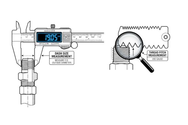
To prevent these expensive complications, you must use precise measuring tools rather than relying on visual estimation. A digital caliper and a pitch gauge are essential field instruments for determining whether a thread is tapered or straight. Straight threads rely on an O-ring or a metal washer to form a seal, whereas tapered threads seal by wedging the thread flanks together.
- A digital caliper captures the exact outer diameter of male threads or inner diameter of female threads.
- A pitch gauge identifies the exact number of threads per inch or the metric distance between thread crests.
- Visual inspections confirm whether the thread profile is parallel or tapered along its length.
| Thread Type | Seal Location | Identification Method |
|---|---|---|
| Tapered (NPT/BSPT) | Thread flanks | Diameter decreases along the thread length |
| Straight (ORB/JIC) | O-ring or 37-degree cone | Diameter remains constant along the thread length |
What Are the Precise Steps to Measure Hose Fitting Dimensions?
Accurate measurements are the foundation of any successful fluid power repair, preventing the frustration of receiving parts that fail to fit. If you guess the size of a hydraulic hose or fitting by eye, you risk purchasing components that restrict fluid flow or fail under operational stress. Fortunately, following a methodical inspection sequence ensures you capture perfect measurements every single time.
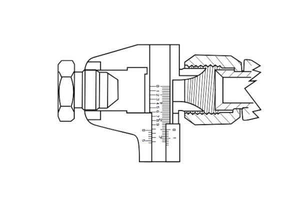
You must measure three critical dimensions: the hose dash size, the thread pitch, and the overall length of the fitting geometry. Dash sizes represent the inner diameter of the hose in sixteenths of an inch, which is vital for maintaining correct fluid velocity. For example, a -08 hose has an internal diameter of 8/16 inches, or precisely half an inch.
- Measure the internal diameter of the hose cleanly using the inside jaws of your digital caliper.
- Determine the thread pitch by placing different gauge leaves against the threads until there is no visible light passing through.
- Document the overall length and drop angle of any elbow fittings to ensure adequate clearance inside the machine chassis.
How to Choose the Correct Sealing Technology for High-Pressure Applications?
Selecting the wrong sealing interface can cause a fitting to weep fluid continuously, even if the threads match perfectly. You might assume that tightening a leaking fitting harder will stop the oil from dripping, but over-torquing a flare or pipe thread will actually split the mating seat and worsen the leak. Understanding how different fittings create their seals allows you to select the best technology for your specific operating environment.
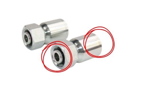
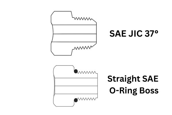
Modern hydraulic systems utilize a variety of sealing interfaces, each engineered for distinct pressure cycles and vibration levels. Flared fittings, such as 37-degree JIC connectors, rely on metal-to-metal contact, while O-Ring Face Seal (ORFS) fittings use a captive elastomeric seal trapped in a machined groove. ORFS connections provide superior leakage protection in high-vibration systems because the elastic O-ring absorbs structural pulses without loosening.
- JIC 37-Degree Flares establish a reliable metal-to-metal seal ideal for extreme temperature ranges.
- O-Ring Face Seals (ORFS) provide maximum leak prevention in high-vibration heavy equipment.
- O-Ring Boss (ORB) straight threads seal ports effectively by compressing an O-ring into a chamfered cavity.
How Do Pressure Ratings and Safety Factors Impact Component Selection?
Exceeding the rated working pressure of a hydraulic fitting can trigger a catastrophic component rupture, endangering workshop personnel and damaging surrounding equipment. You cannot assume that because a fitting threads smoothly onto a high-pressure hose, it is safe to handle the peak operating pressure of the pump system. Every connector is engineered to strict structural limits that must align with your system’s pressure profile.
Before ordering hydraulic fittings, you must confirm both the constant operating pressure and the maximum spike pressure of the hydraulic circuit. Fluid systems regularly experience momentary pressure spikes when control valves shift under full load. The fitting you select must have a working pressure rating that meets or exceeds these spikes, supported by an industry-standard 4:1 safety factor.
- Verify the manufacturer’s nominal working pressure stamped directly on the fitting hex body.
- Account for surge pressures caused by sudden valve closures or rapid cylinder reversals.
- Confirm that the chosen component maintains a 4:1 burst pressure ratio relative to its operating environment.
What Material Selection Criteria Prevent Environmental Corrosion?
Installing carbon steel fittings in an environment exposed to corrosive chemicals or saltwater can cause rapid rust formation, compromising the fitting’s structural integrity within months. You might save on upfront material costs by selecting standard steel components, but the resulting premature failures will drive up your total maintenance expenses over time. Matching component metallurgy to the operating environment is critical for ensuring long-term system reliability.
The most common materials utilized in industrial fluid power fittings are carbon steel, stainless steel, and brass. Carbon steel fittings are generally plated with zinc or zinc-nickel to resist atmospheric moisture, making them excellent for standard factory environments. However, for marine applications, food processing lines, or chemical environments, stainless steel is necessary because its chromium content prevents aggressive oxidation.
- Carbon steel provides excellent mechanical strength and affordability for controlled factory floors.
- Stainless steel delivers superior resistance against chemical washdowns and marine corrosion.
- Brass connectors offer non-sparking performance and reliable sealing for low-pressure fuel lines.
| Environment Type | Recommended Material | Corrosion Resistance |
|---|---|---|
| Industrial Shop | Plated carbon steel | Moderate salt spray resistance |
| Marine / Coastal | 316 stainless steel | High acid and saltwater resistance |
Which Hose-to-Fitting Attachment Methods Match Your Shop Capability?
Attempting to attach a high-pressure hydraulic fitting using incorrect or improvised workshop tools will almost always result in a loose coupling that blows off under load. If you use a hammer or a standard vise to crimp a permanent hose sleeve, the fitting will lack the uniform compression required to hold back thousands of pounds of oil pressure. You must choose an attachment style that aligns with the specific tools available in your maintenance facility.
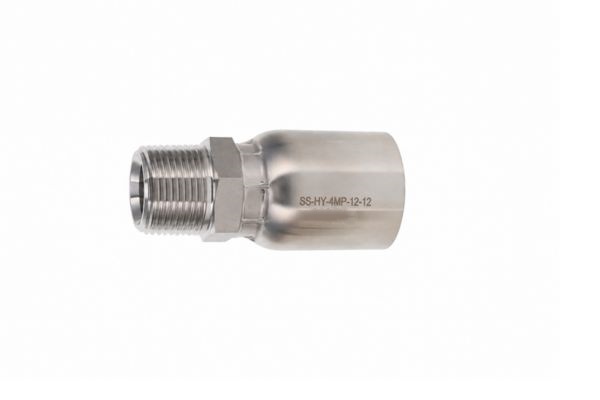
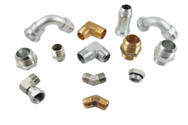
Hydraulic fittings are broadly split into two primary attachment styles: permanent crimped fittings and field-attachable (reusable) fittings. Permanent crimped connectors require an industrial hydraulic crimping machine equipped with specific dies to compress the metal ferrule uniformly around the hose exterior. Field-attachable fittings, by contrast, can be installed directly on-site using standard hand tools and a bench vise, making them ideal for emergency field repairs.
- Permanent crimped fittings offer a highly secure, leak-free connection suitable for mass assembly.
- Field-attachable connectors enable rapid field fixes using only standard wrenches and a vise.
- Push-on fittings provide swift tool-free assembly for low-pressure return or drain lines.
How Do Chemical and Thermal Compatibility Affect Seal Lifespan?
Using a standard Nitrile (Buna-N) O-ring in a system running synthetic phosphate ester fluid will cause the rubber to swell, soften, and degrade within hours of operation. When seals degrade internally, fragments of rubber migrate through the circuit, clogging sensitive valve orifices and scuffing cylinder walls. You must verify that both the fitting metal and the internal elastomeric seals are fully compatible with your system’s fluid type and operating temperature.
Different hydraulic fluids interact chemically with elastomers in unique ways. Standard mineral-based oils are compatible with affordable Nitrile seals, but eco-friendly bio-oils or fire-resistant fluids require specialized compounds like Fluoropolymer (Viton) or Ethylene Propylene Diene Monomer (EPDM). Selecting the correct elastomer ensures the seal retains its elasticity under extreme conditions.
- Nitrile (Buna-N) seals deliver reliable performance in standard mineral-based hydraulic oils.
- Fluoropolymer (Viton) provides exceptional defense against high temperatures and synthetic fluids.
- EPDM compounds excel in phosphate ester fluids but degrade rapidly if exposed to petroleum.
| Elastomer Compound | Temperature Range | Fluid Compatibility |
|---|---|---|
| Nitrile (Buna-N) | -40°C to 120°C | Standard petroleum mineral oils |
| Viton (FKM) | -20°C to 200°C | Synthetic fluids and bio-oils |
Reviewing these chemical relationships highlights how selecting advanced fluoroelastomers protects your system against leaks caused by thermal hardening, keeping connections secure during prolonged, high-temperature operations.
What Flow Velocity and Port Configuration Rules Optimize Efficiency?
Using a hydraulic fitting with an internal diameter that is too narrow creates a severe restriction in the fluid path, forcing your system to work harder to push oil through the circuit. This restriction generates localized friction, which rapidly heats the hydraulic fluid and wastes engine horsepower as heat. To maintain high system efficiency, you must select fittings that support proper fluid velocity without causing excessive backpressure.
Before ordering hydraulic fittings, you must evaluate the system’s overall plumbing configuration, including fluid flow rates and the physical style of the connection ports. Opting for swept 90-degree elbow fittings instead of sharp, blocky 90-degree configurations significantly reduces fluid turbulence. Swept elbows allow the fluid to transition smoothly around corners, preserving system pressure and reducing internal wear.
- Size fitting internal diameters to match the hose ID exactly, avoiding restricted fluid flow.
- Choose swept-bend elbow configurations over sharp blocks to eliminate localized pressure drops.
- Confirm whether your component ports require adjustable or non-adjustable male orientation styles.
Conclusion
Sourcing high-pressure fluid power components does not have to be a stressful exercise in trial and error. By implementing a rigorous physical verification framework—measuring thread diameters with calipers, identifying pitch with thread gauges, aligning pressure limits with structural safety factors, and matching metallurgy to the operating environment—you can remove the guesswork from system maintenance. When you are ready to restock your parts inventory or source specialized connectors for a rebuild, please contact us today to access engineering-grade fluid power solutions tailored to your operational needs.
Frequently Asked Questions
Can I mix NPT and BSPT threads if the diameters seem identical?
No, you must never mix NPT and BSPT threads. While they share similar taper profiles and can occasionally feel like they are threading together, they utilize completely different thread pitches and crest angles (NPT uses a 60° thread angle, while BSPT uses 55°). Forcing them to mate will permanently strip the threads and create an unreliable, high-pressure leak path.
What’s the best way to determine if my fitting thread is tapered or straight?
The most reliable method is to measure the thread diameter at two separate points along its length using a digital caliper. If the outer diameter remains completely uniform from the first thread to the last, it is a straight thread that requires an O-ring or washer to seal. If the diameter visibly decreases toward the end of the fitting, it is a tapered thread that seals via mechanical wedging.
How do I know if an O-ring needs replacement when servicing a fitting?
You should replace an O-ring whenever the fitting assembly is disassembled for maintenance, or if the rubber shows any signs of flattening, cracking, pitting, or hardening. Reusing a crushed or brittle elastomeric seal compromises the fitting’s pressure rating, leading to slow oil weeping once the system reaches full operating temperature.
Can I use brass fittings on a heavy equipment hydraulic system?
No, you should not use standard brass fittings in heavy industrial hydraulic circuits. Brass lacks the mechanical tensile strength required to handle the high operating pressures (often exceeding 3,000 PSI) typical of modern equipment loaders and pumps.
How do I measure the dash size of a hydraulic hose accurately?
You can measure the dash size by taking the inner diameter of the hydraulic hose in inches and converting it into sixteenths of an inch.