Why One-Piece Fittings Pull Off and How to Prevent It

Why One-Piece Fittings Pull Off and How to Prevent It

A one-piece hydraulic hose fitting can pull off when the hose, fitting, insertion, crimp, or assembly process is wrong. Preventing that failure requires all five checks below—not simply a tighter crimp. For a hose assembly shop, this approach reduces rework and helps keep an incorrectly built assembly from reaching a machine.

Why One-Piece Fittings Still Pull Off

The one-piece design removes one mismatch, not every mismatch

A one-piece fitting has a fitting body or stem and a ferrule preassembled or fixed as one assembly component; the exact construction varies by product series. This arrangement prevents an operator from selecting a separate, incorrect ferrule, which is a useful error reduction. It does not automatically make the fitting compatible with every hose of the same nominal size, create the correct crimp, or guarantee retention under pressure impulses and mechanical loading.
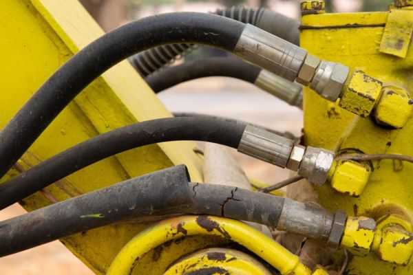
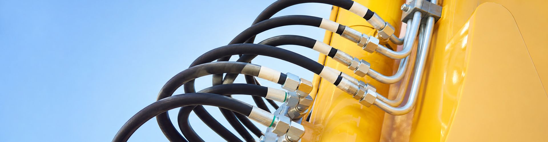
bend routing

Pull-off is usually a system failure

Retention comes from a controlled relationship among the fitting stem profile, ferrule deformation, hose reinforcement, insertion depth, and finished crimp diameter. If any one of those relationships falls outside the qualified assembly specification, the fitting may move, leak, or separate. The five checks are therefore connected: passing four does not compensate for failing the fifth.

Before examining an assembly, shut down the equipment, release hydraulic pressure and stored energy, and follow the equipment and component manufacturers’ safety procedures. Never search for a pinhole leak with a hand, and never loosen a connection to “see whether pressure remains.” Fluid injection injuries and uncontrolled hose movement require immediate, serious treatment.

Check 1: Match the Hose Construction to the Fitting Series

Size alone cannot establish compatibility

The first check is whether the exact one-piece fitting series is approved for the specific hose manufacturer, hose series, size, and construction. Two hoses marked with the same dash size may differ in tube material, reinforcement type, reinforcement position, cover thickness, and outside diameter. Those differences affect how the stem enters the bore, how the ferrule compresses the hose, and whether the reinforcement is captured as intended.

Use current, traceable manufacturer crimp data rather than a visual comparison with an old assembly. A stem that appears to fit can still damage the tube, push reinforcement aside, or fail to develop retention. If the hose and fitting come from different product systems, do not assume cross-brand compatibility from dimensions or catalog language; obtain documented approval or use a validated combination.

Confirm the complete hose-and-fitting identity

Record the following before cutting or crimping:

The working capability of the finished hydraulic hose assembly is governed by its lowest-rated component and by application conditions. A fitting’s catalog rating by itself does not qualify the complete assembly. When the combination is absent from the current crimp data, stop and resolve the gap rather than substituting a “close” series.

Check 2: Control Hose Preparation and Full Insertion

A correct crimp cannot recover missing insertion depth

The hose must reach the position defined by the assembly instructions before crimping. If it stops short, the ferrule may compress cover or reinforcement in the wrong zone, leaving too little effective engagement with the stem. Causes include an angled cut, debris in the bore, a damaged stem, incorrect skiving, insufficient lubrication where an approved lubricant is specified, or simple loss of the insertion mark during handling.
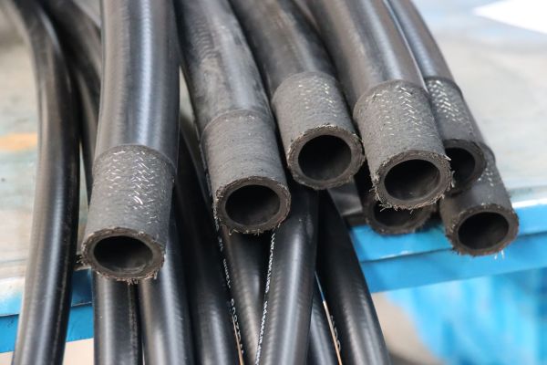
Crimping hose process

Cut the hose square with suitable equipment, inspect the bore, and clean it according to the required cleanliness process. Follow the exact preparation instruction for skiving, cover removal, cleaning, and approved lubricant; these details are series-specific. Over-skiving can remove material needed for support, while under-skiving can prevent insertion or change how the ferrule loads the reinforcement.

Mark insertion before the assembly enters the crimper

Use the manufacturer’s specified insertion depth or insertion reference and place a visible mark at the ferrule edge. After inserting the hose fully, verify the mark has not shifted before crimping and check it again afterward. Some product designs provide an inspection hole or other feature, but use it only as the manufacturer directs; it does not replace the specified depth check.

A practical insertion control should answer four questions:

If the insertion mark moves, do not recrimp and release the assembly without an approved disposition. Determine whether the hose backed out, the fitting was mispositioned in the dies, or the preparation prevented full engagement. Rework rules must come from the applicable hose-and-fitting manufacturer because additional crimping can further damage reinforcement or distort the stem.

Check 3: Apply the Exact Crimp Specification

Crimp diameter is product-specific

The correct finished diameter, tolerance, die selection, and measurement location come from current data for the exact hose-and-fitting combination. There is no universal crimp diameter for a dash size, and “slightly smaller for more grip” is unsafe reasoning. Excessive crimp can damage reinforcement, restrict the tube, or deform the stem; insufficient crimp can leave inadequate ferrule engagement and allow pull-off or leakage.

Retrieve the approved specification at the workstation and confirm that the crimper, die set, and settings correspond to it. Crimp data can change with hose series, fitting family, size, production design, or tooling. A handwritten value copied without its source, revision, product scope, and measurement convention is not enough to release an assembly.

Measure the finished crimp correctly

Measure only after the assembly and measuring tool are in the condition required by the procedure. Use a calibrated instrument with suitable contact surfaces, take measurements at the specified location, and avoid distorted areas such as die impressions or part markings unless the instructions state otherwise. If the procedure calls for readings around the circumference, record them; a single favorable reading can hide taper or an uneven crimp.

When a finished diameter is outside tolerance, quarantine the assembly and follow the documented nonconformance process. Do not average an out-of-limit reading into acceptance or change the target to match what the machine produced.

Check 4: Verify the Crimper, Tooling, and Process

Good parts can fail in an uncontrolled process

A correct hose and fitting can still produce a weak joint when the crimper is miscalibrated, the wrong dies are installed, tooling is worn or contaminated, or the fitting sits incorrectly in the die cage. Machine display values do not by themselves prove the resulting diameter. Verification must connect the selected program and tooling to a physical measurement of the finished crimp.

Establish a pre-use check covering machine status, calibration or verification status, die identity, die cleanliness, visible wear, and the correct setup for the fitting shape. Elbows and long-drop fittings may need particular positioning to prevent interference or side loading. Operators should also confirm that the ferrule is located at the intended crimp position rather than centered by appearance.
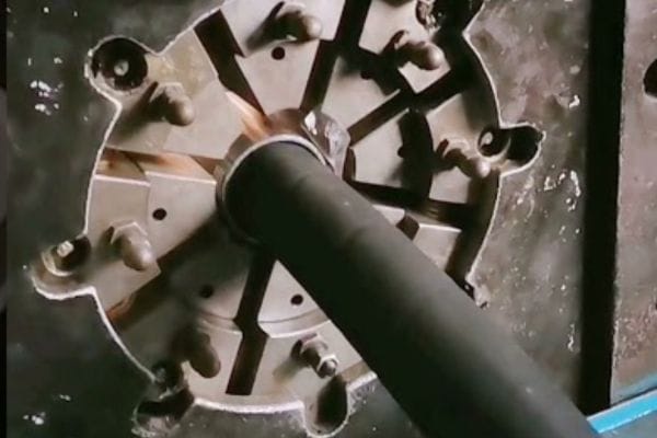
Crimping Mistakes

Lock the specification to the job traveler

The build record should carry enough information for another qualified person to reproduce and inspect the assembly. At minimum, connect the hose part number, fitting part number, preparation method, insertion control, crimp specification revision, machine, dies, measured results, and operator or station identity. Barcode scanning or controlled digital recipes can reduce transcription mistakes, but only when part labels and master data are accurate.

Use these process gates before releasing production:

These controls are especially valuable during urgent repairs, when speed creates pressure to rely on memory. A short pause to verify a recipe is faster than disassembling a machine again after leakage or pull-off.

Check 5: Inspect, Test, and Release the Finished Assembly

Inspection must look beyond the crimp number

A diameter within tolerance is necessary, but it is not the entire release decision. Inspect the insertion mark, ferrule position, crimp length and uniformity as applicable, exposed reinforcement, cracks, die damage, stem-bore distortion, hose twist, fitting orientation, cleanliness, and end-connection condition. Confirm that routing will not impose tension, excessive bend, abrasion, or side load near the fitting after installation.

Thread form and sealing method also deserve separate verification. JIC, SAE 45-degree flare, NPT/NPTF, BSPP/BSPT, ORFS, ORB, metric, DIN, and JIS connections are not interchangeable merely because they appear to mate. Measure diameter and pitch or TPI, distinguish straight from tapered threads, and identify the seat, sealing face, or O-ring arrangement; thread sealant cannot repair a mismatched thread or damaged sealing surface.

Testing follows the applicable procedure

Perform proof, pressure, cleanliness, electrical-continuity, or other testing only when required and according to the applicable manufacturer, customer, equipment, or quality procedure. Use guarded equipment and keep personnel away from a pressurized assembly. A shop-made pull test or arbitrary pressure test is not a substitute for a qualified hose-and-fitting system or for the specified production inspection.

Release the assembly only when its identification and records agree with the physical build. Cap or protect cleaned ends as required, prevent contamination during storage, and label the assembly so that a future replacement can be traced without guessing.

What to Do When Pull-Off or Hose Movement Is Found

Quarantine first, investigate by evidence

If a fitting has moved, leaked at the hose-to-fitting interface, or separated, stop the equipment, isolate energy, and quarantine the assembly and related production. Do not push the hose back into the ferrule, tighten an unrelated threaded connection, or add sealant. Preserve the hose, both fittings, labels, build record, machine data, dies used, and operating information so the failure can be assessed without destroying its clues.

The investigation should compare physical evidence with the five controls rather than jump to a single cause. Check whether the correct hose and fitting were used, whether insertion evidence remains, whether crimp measurements and tooling records are credible, whether the assembly shows twist or external loading, and whether operating pressure, impulse, temperature, fluid, and routing were within the qualified limits. Similar assemblies made since the last verified process check may also need controlled segregation and review.

Information needed for a reliable technical review

Prepare a concise evidence package:

This record supports a technical decision without assuming that every separation is caused by under-crimping. It also makes the next replacement faster: the shop can retrieve verified details instead of identifying a damaged part from one photograph. Where recurring failures involve routing, vibration, or abrasion, consult the equipment and hose manufacturers before changing fitting orientation, hose length, clamps, or protective measures.

A Practical Release Rule for One-Piece Fitting Pull-Off Prevention

Five passes are required

Release a one-piece hydraulic hose fitting assembly only after the hose/fitting match, preparation and insertion, crimp specification, controlled tooling process, and final inspection all pass against traceable requirements. One-piece construction reduces the chance of choosing a separate ferrule incorrectly, but it cannot compensate for an unapproved hose, shallow insertion, an incorrect crimp, uncontrolled tooling, or damaging installation conditions.

Before the next build or technical inquiry, prepare the exact hose and fitting part numbers, current manufacturer crimp data, insertion requirement, machine and die information, measured crimp results, application conditions, and clear component photos. Correct matching is more important than visual similarity, speed, or the lowest component price because the finished assembly must work as one qualified system.

Frequently Asked Questions

Can a one-piece fitting be recrimped if the hose moves after crimping?

Do not recrimp it unless the hose-and-fitting manufacturer provides an approved rework instruction for that exact condition. Quarantine the assembly, document the movement and measurements, and determine why insertion or retention failed.

Does the same dash size mean a different hose brand will fit?

No; dash size identifies nominal size, not complete hose construction or approved fitting compatibility. Confirm the exact hose series, fitting series, and current crimp data before assembly.

Can a smaller crimp diameter prevent pull-off?

Only the specified crimp target and tolerance may be used. Crimping smaller than specified can damage reinforcement, the tube, or the fitting stem without creating a safe joint.

Is pressure testing enough to prove fitting retention?

No; a production pressure test, when required, evaluates the assembly under the defined test conditions but does not excuse incorrect components or process results. Compatibility, insertion, crimp measurements, tooling control, and final inspection still need independent verification.

Should a separated assembly be cut apart immediately?

No; first isolate it, preserve its as-found condition, photograph it, and collect the build and application records. Cutting can destroy evidence needed to distinguish shallow insertion, incorrect crimping, incompatible components, or external loading.
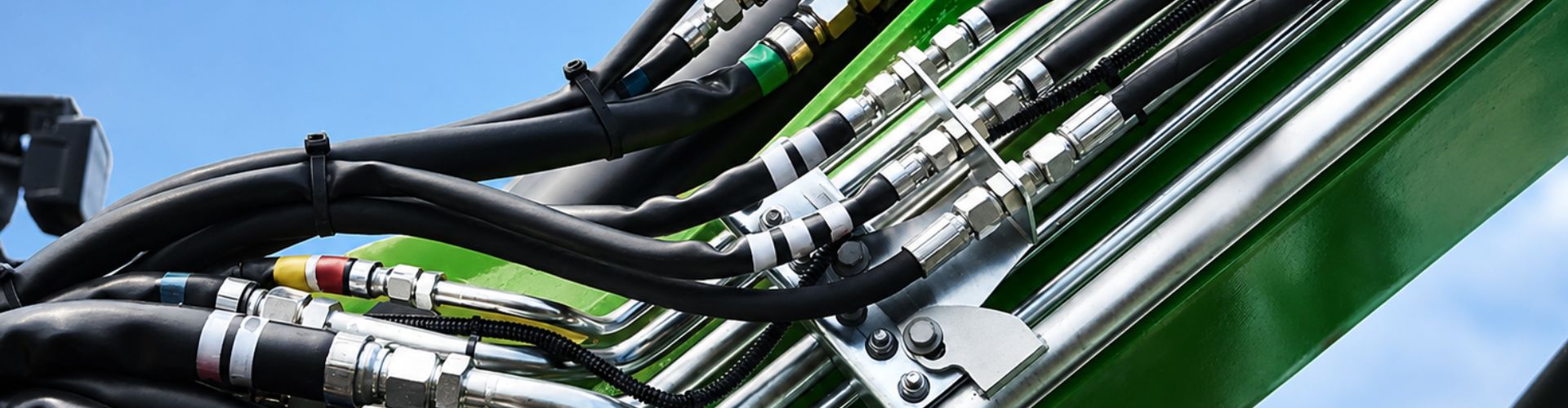
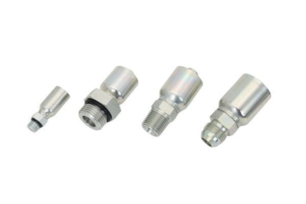
One-Piece Fitting Identification

One-Piece Fitting Identification: Photos and Details to Send

Clear photographs can narrow down a one-piece hydraulic hose fitting, but photographs alone rarely establish an exact replacement. Send an organized photo set together with thread, sealing-face, hose, and application information so the recipient can verify the connection instead of matching by appearance. This reduces repeated questions, incorrect quotations, assembly rework, leakage risk, and avoidable equipment downtime.

What Can a Photo Actually Confirm?

Use images for screening, not final interchange approval

A useful photo set can show whether the item appears to be a straight, 45-degree, or 90-degree one-piece fitting; whether the port end is male or female; and whether the visible construction resembles a common JIC, ORFS, pipe-thread, BSP, metric, DIN, or other connection family. It can also reveal an elbow orientation, swivel nut, flange shape, O-ring location, ferrule profile, corrosion, impact damage, and any readable markings. These observations quickly remove many unsuitable candidates and tell the reviewer which dimensions to request next.

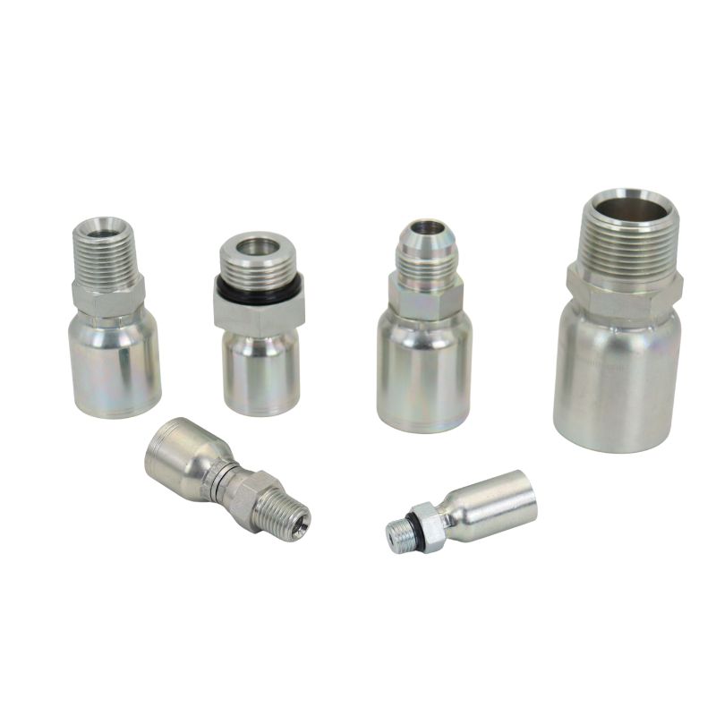
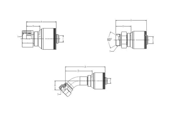
One piece Hydraulic Fitting types

A photograph does not reliably establish thread pitch, a small difference in seat angle, the distinction between parallel and tapered threads, or compatibility with a particular hose and crimp specification. Two connections may look nearly identical on a phone screen while using different thread forms or sealing methods. Treat photo identification as a controlled shortlist: the image proposes possibilities, and measurements plus product data confirm or reject them.

The Essential One-Piece Fitting Photo Set

Photograph the complete part before taking close-ups

Start with a clean, well-lit overview showing the complete fitting from the side. Place it on a plain background, keep the camera square to the part, and include a ruler for scale without using the ruler as a substitute for caliper measurements. For an elbow, take another view looking along the hose or stem axis so the reviewer can understand its orientation rather than guessing from a flattened side image.

Then photograph every marking on the fitting and hose. Rotate the part because a stamped code, logo, dash size, or series mark may appear on a different wrench flat or ferrule face. Include one image of the entire hose assembly when available; the relationship between the two ends, overall routing, guards, sleeves, and adapters may explain details that an isolated close-up hides.

Capture the connection and sealing surfaces directly

Take close-ups straight toward the thread and straight toward the sealing face. A side view should show the full threaded length and whether the diameter changes along it; an end view should show a cone seat, flat face, O-ring groove, flare, nose, or other sealing feature. Clean away loose dirt carefully, but do not grind, polish, or reshape a damaged surface merely to make the photograph clearer.

Send the following image set as the practical minimum:

Sharp focus matters more than a large file. Use indirect light to avoid glare from plated steel, tap the thread or seat on the phone screen to focus, and review each image at full size before sending it. If the connection is still installed, shut down the equipment, release hydraulic pressure and stored energy, and follow the equipment and component manufacturers’ safety procedures before removal or close inspection.

Measurements That Must Accompany the Photos

Measure the thread instead of estimating it from a ruler

Provide the male thread outside diameter or female thread inside diameter, measured with calipers across the thread crests where the connection standard calls for that reference. Record the value in millimeters or inches and state which unit you used. Add the pitch in millimeters for metric-style descriptions or threads per inch (TPI) as appropriate, preferably checked with a thread-pitch gauge rather than inferred from a blurry image.

Also report whether the thread appears straight or tapered and whether it is male or female. Do not force a known nut, adapter, or gauge onto an uncertain connection as a trial fit: partial engagement does not demonstrate compatible thread form or sealing. Nominal names often do not equal the measured diameter, so send the actual reading rather than converting it into a guessed size.

Male Hydraulic Crimp Fitting

Describe the seat and seal separately from the thread

The thread retains the connection, but it may not create the fluid seal. State whether sealing occurs on a metal cone or flare, a flat face with an O-ring, a bonded seal, a tapered thread, an O-ring boss, or another feature. If a seat angle must be confirmed, use the correct gauge or compare the geometry through authoritative product data; perspective distortion makes angle measurements from photographs unreliable.

Record the tube or flange dimensions when those features form part of the connection. For a used item, note flattened O-rings, scoring, fretting, cracks, corrosion, or an uneven witness mark, because damage can disguise the original geometry. Thread sealant must not be used to compensate for an incompatible thread or a damaged sealing face.

Hose and Crimp Information the Image Cannot Supply

Identify the hose from its layline and construction

Send the hose manufacturer, exact series, hose inside diameter or dash size, and a clear photograph of the complete layline. If the layline is unreadable, do not assume size from the hose outside diameter; cover thickness and reinforcement construction vary. Note whether the original assembly was skived, but use the applicable hose-and-fitting manufacturer instructions to decide whether a replacement requires skiving.

The fitting tail and ferrule may look like another product series while having different stem dimensions, tooth profiles, shell lengths, or intended hose constructions. Equal dash sizes do not make two products compatible. When the hose cannot be identified, the responsible next step may be to identify and replace the complete hose assembly under an approved system rather than copy an uncertain fitting-hose combination.

Obtain valid crimp data for the exact combination

Supply the crimping machine model, available die information, and any verified crimp specification associated with the hose and fitting series. The correct crimp diameter, measurement location, insertion depth, die choice, skive requirement, and assembly procedure must come from current data applicable to that exact combination. A value copied from a similar-looking fitting or another manufacturer’s series is not a safe substitute.

One-piece construction can reduce the chance of picking the wrong loose ferrule, but it cannot make an unsupported hose-and-fitting combination valid. The finished assembly is limited by its components, connection, assembly quality, pressure impulses, temperature, fluid, routing, and service conditions. For safety-critical or high-consequence equipment, escalate uncertain identification to the equipment, hose, fitting, or crimp-equipment manufacturer as appropriate.

How to Send a Request That Can Be Checked

Label the images and state the required outcome

Use simple filenames such as 01-overall, 02-male-thread-side, 03-sealing-face, and 04-hose-layline, then match each measurement to the relevant image. Transcribe markings in the message because characters that look like 0/O, 1/I, or 5/S may remain ambiguous in a photograph. State whether you need preliminary identification, a quotation, a replacement assembly, or verification of an existing candidate; each outcome needs a different level of evidence.

Include the quantity and whether the parts are for a repair, stock replenishment, resale, or equipment production. Add the equipment make and model when it can help locate an approved parts record, but do not assume the original equipment identifies every replacement hose installed later. If an existing part number is available, give its source—fitting, hose tag, drawing, invoice, or equipment manual—so the reviewer can judge how directly it relates to the physical part.

Copy this compact identification checklist

If any field is unknown, write “unknown” rather than filling it with a visual guess. That distinction lets the reviewer isolate what still requires inspection, a gauge, a drawing, or manufacturer confirmation. It also preserves a traceable record for later receipt inspection and future replacement.

Common Photo-Identification Failures

Similar appearance is not evidence of interchangeability

The most frequent error is selecting a connection because its diameter and general shape resemble the old one. JIC and SAE 45-degree flare connections, various BSP and pipe-thread forms, metric and DIN geometries, and different O-ring arrangements can be confused when scale and seat details are missing. A wrong choice may begin threading, yet damage the mating port, fail to seat, loosen under vibration, or leak under pressure.

Another failure is photographing only the damaged end. Crushed threads, a missing O-ring, an eroded cone, or a cut-off ferrule can conceal the feature needed for identification. Photograph the mating port or adapter separately when accessible, record where the failed part was installed, and retain the old assembly until the replacement has been fully verified.

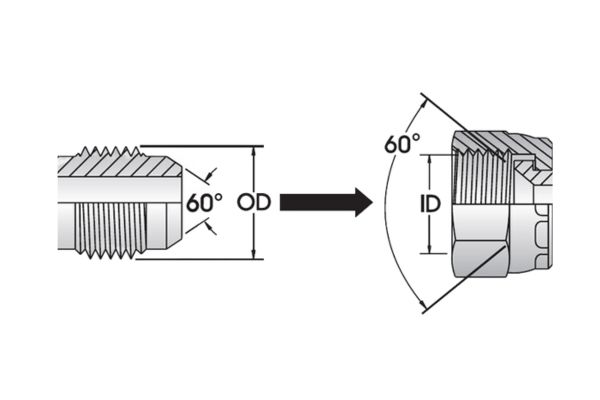
JIS 60° Cone Seat Fitting

Do not let urgency remove the safety checks

Downtime creates pressure to accept the first plausible match, but an uncertain fitting should not be installed merely because it screws in or can be crimped. An incorrect thread or sealing face can leak; an unsupported hose-and-fitting combination can damage the hose, pull off, or fail unpredictably. Fluid injection injuries and uncontrolled equipment movement are serious hazards, so never search for a pinhole leak with a bare hand and never dismantle a pressurized system.

After assembly, follow the applicable inspection, cleaning, installation, and test procedures for the equipment and approved hose system. Check routing, bend radius, twist, abrasion exposure, clearance, and connection engagement, not just the fitting’s visual similarity. Record the confirmed part number, hose series, end styles, orientation, length, crimp reference, and installation location so the next replacement begins with evidence rather than another photo-only search.

Frequently Asked Questions

Can a supplier identify a one-piece fitting from one photo?

Usually not with enough certainty for final selection. One image may indicate a connection family or elbow style, but it rarely proves thread pitch, seat geometry, hose series, or crimp compatibility. Send the complete photo set and measured data even when the item looks common.

Should I place a ruler next to the fitting?

A ruler provides useful scale, but it does not replace calipers or a thread-pitch gauge. Camera angle, lens distortion, and coarse ruler marks can shift the apparent dimension. Include the ruler in an overview, then write down the measured thread diameter and pitch separately.

What if the hose layline has worn off?

Treat the hose series and construction as unconfirmed. Check tags, maintenance records, equipment documentation, purchase records, and any readable section of the layline. If compatibility cannot be established, use an approved identification and replacement process for the complete assembly rather than assuming that matching dash size is sufficient.

Is an existing part number enough without measurements?

It may be enough to locate a candidate, but physical verification is still prudent when the number’s source is uncertain or the assembly may have been modified. Compare the candidate’s connection, dimensions, hose compatibility, material, and applicable crimp data against the actual requirement. A branded number can support cross-checking but does not by itself prove another product is fully interchangeable.

What should I do if the thread and seat still cannot be identified?

Stop treating the request as a photo match and escalate it for direct inspection or authoritative data review. Preserve the old part and mating component, use suitable gauges, and consult the relevant equipment or component manufacturer information. Do not repair uncertainty with thread sealant, forced engagement, or an improvised adapter stack.

How to Identify One-Piece Fitting Seal Mismatch Before Crimping

How to Identify One-Piece Fitting Seal Mismatch Before Crimping?

A one-piece fitting seal mismatch should be found before crimping by identifying where the connection is designed to seal, then verifying the thread form, seat angle, sealing face, and any O-ring against the mating port or adapter. A fitting can thread into another component and still have the wrong sealing method. Once it has been crimped onto a hose, the shop may have to scrap the assembly, rebuild it, or risk sending a connection into service that can leak under pressure.

Understand What a Seal Mismatch Actually Means

Thread engagement does not prove sealing compatibility

A seal mismatch exists when the selected connection cannot create the intended seal with its mating component, even if the threads appear to start or tighten. Hydraulic connections may seal on metal seats, an O-ring, a bonded seal, a flare, a cone, a flat face, or properly specified pipe threads, depending on the connection design; the thread may provide mechanical retention while a different surface contains the fluid, so thread diameter alone cannot identify the sealing method. For example, two straight-thread fittings can use different seats or seals, while two tapered thread forms that appear close may differ in form or intended interference.

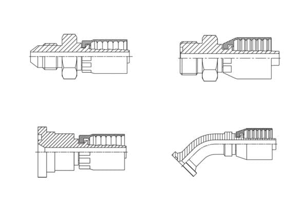
One piece Hydraulic Fitting component

One-piece construction solves a different matching problem

In a one-piece hydraulic hose fitting, the fitting body or stem and ferrule are preassembled or fixed as one assembly component; the precise construction depends on the series. This format can reduce errors caused by selecting a separate ferrule that does not belong with the stem, but it does not verify the connection end, mating port, hose series, or crimp settings. One-piece does not mean reusable, field attachable, universally compatible, or automatically leak free; a shop still has two independent decisions: whether the fitting seals to the equipment connection and whether its hose tail and ferrule match the hose construction and approved assembly procedure. Keeping those decisions separate prevents a correct hose-side selection from hiding a wrong port-side seal.

Identify Where the Connection Is Designed to Seal

Compare the common sealing locations

The fastest reliable check begins at the sealing surface rather than the hex or general fitting shape. Clean the removed part using the approved maintenance procedure, then inspect the nose, internal cone, external flare, flat face, O-ring groove, washer location, and thread profile without altering them; a JIC connection uses a different seat concept from an SAE 45-degree flare; ORFS, ORB, BSPP arrangements, tapered pipe threads, Metric cone systems, DIN forms, and JIS connections also require their own identification evidence. These names describe different combinations of connection standard, thread form, seat geometry, and sealing method. They must not be treated as visually interchangeable groups.

Read witness marks without letting them overrule dimensions

Contact marks on an old seat can show where two parts touched, but they cannot by themselves prove that the original connection was correct. A narrow, off-center, incomplete, or damaged witness mark may indicate a seat-angle mismatch, misalignment, contamination, over-tightening, or a previously incorrect replacement. Inspect the mating adapter or port as well as the hose fitting because damage can exist on either side; do not use thread sealant to compensate for a metal-seat mismatch, missing O-ring, damaged face, or incorrect thread; sealant cannot create the required geometry. If the seat is deformed, the original profile may no longer be measurable, so part-number or equipment documentation becomes more important than visual comparison.

Collect the Right Evidence From the Old Assembly

Photograph and measure before discarding the failed part

An old assembly should be treated as evidence, not automatically as a correct specification. Before disposal, photograph the complete fitting, connection end, thread profile, sealing face, O-ring location, hose layline, and orientation of any elbow relative to the hose; measure the relevant outside or inside thread diameter and determine pitch or threads per inch with appropriate gauges; also note whether the thread appears straight or tapered. Record the sex of the connection, seat location, apparent seat angle using the proper inspection method, and any part number that remains readable.

Check the mating port instead of copying the removed fitting

The removed fitting may already be a mismatched substitute, which makes copying it a repeat of the earlier error. Inspect or identify the equipment port, adapter, tube end, or manifold connection that the new hose assembly must join. Look for an equipment parts listing, port designation, adapter marking, controlled drawing, or previous verified service record, then compare that evidence with the physical measurements; where the port is difficult to access, clear photographs should show the full connection and sealing surface, not just the opening. If documentation and the removed part disagree, stop and resolve the conflict before crimping; the equipment, port, or component manufacturer’ current data should take priority over an undocumented visual match.

Bring the following evidence to the bench:

Use a Step-by-Step Pre-Crimp Seal Check

Identify thread, seat, and seal as separate attributes

Start by confirming whether the connection is male or female, then identify the thread form from diameter, pitch or TPI, flank characteristics where applicable, and straight or tapered geometry. Next, locate the intended sealing surface and determine whether it relies on a flare, cone, face seal, port O-ring, washer, or specified pipe-thread interface; compare the seat angle and geometry using appropriate gauges or documented dimensions rather than estimating by eye. Finally, confirm that the mating component provides the corresponding surface and that an O-ring or other seal is present only where the design calls for it. This sequence prevents a familiar thread label from becoming a shortcut for assumptions about the seat and seal.

crimp hydraulic fitting design

Perform a dry comparison without forcing the parts

A controlled, unpressurized comparison can reveal obvious problems, but it is not a substitute for specification verification. Threads should start correctly without cross-threading or abnormal resistance, yet easy engagement still does not confirm that the seats meet; inspect the relationship between the two sealing surfaces, required seal position, available thread engagement, shoulder clearance, and orientation before applying any assembly torque. Do not force mismatched parts together to create a witness mark, modify a seat, stack seals, or add sealant as a diagnostic method. If the fitting cannot be identified from documented geometry and the mating specification, quarantine it until the connection manufacturer information or a verified sample resolves the uncertainty.

Use this decision order before approving the connection end:

Confirm the Hose Side Before Crimping

Match the fitting series to the exact hose construction

Correct port sealing does not make the hose side compatible; confirm the hose manufacturer and series, reinforcement construction, hose ID or dash size, and the one-piece fitting series intended for that hose. The same nominal hose size can appear across products with different cover, reinforcement, wall, and fitting requirements. The fitting stem, ferrule, and hose must belong to a documented assembly system or an otherwise validated combination supported by applicable technical data. A one-piece format reduces the need to choose a loose ferrule, but it cannot prevent selection of the wrong preassembled fitting series.

hydraulic hose measure Topa

Use current crimp data for the actual combination

Crimp diameter, die selection, insertion depth, skive or no-skive preparation, and inspection criteria must come from current data applicable to the hose, fitting, and crimping equipment. Do not copy a crimp value from a fitting that shares the same dash size or resembles the replacement; mark insertion depth as required by the documented procedure, verify full insertion before crimping, and inspect the completed assembly according to that system instructions. The complete assembly pressure suitability depends on its lowest-rated component or interface and on fluid, temperature, impulse, routing, and installation conditions.

Know What a Missed Mismatch Can Cause

Leakage may appear immediately or after service begins

A wrong seat or sealing face can leak during initial testing, but some mismatches create partial contact that appears tight before pressure, temperature, impulse, or vibration exposes the problem. Over-tightening may temporarily reduce visible seepage while deforming a seat, damaging a thread, extruding an O-ring, or transferring load into the wrong surface; the result can include fluid loss, contamination entry, rework, damaged adapters, and an unplanned shutdown. A connection that needs unusual force to stop leaking should not be accepted as proof of compatibility. Shut the equipment down, release hydraulic pressure and stored energy, and follow the equipment and component manufacturers safety procedures before inspection.

A wrong diagnosis can damage more than the fitting

If a leak is blamed on crimping when the actual fault is a connection-end mismatch, the shop may recrimp or replace the hose without correcting the seal. If the leak is blamed on a missing seal when the design uses a metal seat, an added O-ring or washer can prevent proper engagement and introduce another failure point; cross-threading, poor alignment, damaged sealing faces, incorrect hose routing, and incompatible fluids can also resemble a seal problem, so diagnosis must consider the complete assembly. Never search for a pinhole leak with a hand, disconnect a pressurized line, or install an unverified fitting as a temporary repair. Suspected injection injuries require immediate medical attention even when the external wound appears small.

Make the Crimp-or-Stop Decision Explicit

Use a neutral pre-crimp release checklist

Release the fitting for crimping only when the evidence forms one consistent specification. The work record should identify the hose manufacturer and series, hose size, fitting style and orientation, connection sex, measured thread diameter, pitch or TPI, straight or tapered form, seat angle, sealing method, and existing part number where available; attach clear photos of the complete fitting, thread, and sealing face, plus the relevant equipment or port information. Record the fluid, working pressure, temperature, application, and any material or finish requirement that affects suitability. Finally, identify the crimping machine and the current crimp specification for the exact hose-and-fitting combination; if any safety-critical field is unresolved, the correct decision is to stop rather than guess.

Correct matching is the final acceptance criterion

Finding a one-piece fitting seal mismatch before crimping protects the hose assembly from avoidable scrap, leakage, damaged ports, and repeat downtime. The decisive question is not whether two fittings look alike or whether the threads can be started; it is whether the measured thread, seat, sealing method, hose series, and documented crimp procedure agree with the mating connection and application. Prepare the old part, mating-port evidence, thread measurements, sealing-face photos, hose layline, operating conditions, and current assembly data before releasing the job; when identification remains uncertain, consult the equipment, hose, fitting, port, or crimp-equipment manufacturer applicable information. Correct compatibility carries more weight than speed, unit price, or a visual cross-reference.

Frequently Asked Questions

Seal Identification Questions From the Assembly Bench

Can two fittings with the same thread size use different seals?

Yes. A thread designation does not always define the seat angle, sealing face, O-ring arrangement, or mating geometry. Confirm the complete connection standard and sealing method before treating two fittings as substitutes.

Can an O-ring be added to stop a metal-seat connection from leaking?

No, not unless the documented connection design specifically requires that O-ring in that location. An added seal can obstruct engagement, become cut or extruded, and hide a damaged or mismatched metal seat.

Does a successful low-pressure check prove the seal is correct?

No. A partial contact or deformed seal may appear acceptable initially but respond differently to working pressure, impulse, temperature, or vibration. Follow the applicable inspection and test procedure for the verified hose assembly and connection.

Should a damaged old fitting be used to measure the seat angle?

Only with caution. Wear, deformation, corrosion, or earlier over-tightening can change the surface you are trying to identify. Use undamaged features, mating-component evidence, part numbers, and manufacturer dimensions to resolve the specification.

Is thread sealant acceptable on every tapered hydraulic connection?

No. The connection specification determines whether a sealant is permitted, which type is suitable, and how it should be applied. Sealant must never be used to repair the wrong thread form, damaged threads, or a mismatched sealing design.

Contact Topa

Save 30% on maintenance costs with our easy-install hydraulic fittings. Contact Now!