How to Review a One-Piece Hose Assembly Test Report

How to Review a One-Piece Hose Assembly Test Report?

The first question for any one-piece hose assembly test report is simple: which exact assembly was tested? A statement that a sample “passed” is difficult to evaluate when the report does not identify the hose, fitting, crimp process, test method, conditions, measured results, and acceptance basis. Good documentation lets an engineering or purchasing reviewer determine what the evidence supports, what it does not support, and whether it applies to the proposed product.

Identify the Exact Assembly Under Test

Product identity defines the boundary of the report. If the tested configuration cannot be reconstructed from controlled records, the result cannot responsibly be extended to a purchase or application decision.

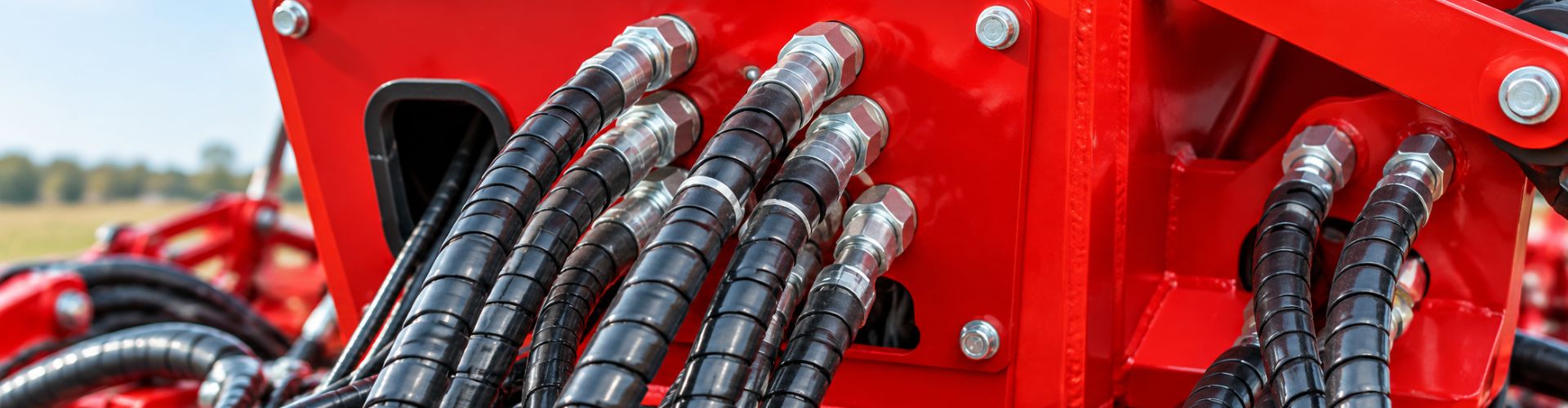
hydraulic hose measure Topa

Record the hose and both end fittings

List the hose manufacturer, full hose designation, series, size, construction where required, manufacturing or lot traceability, and the condition or preparation relevant to the test. Identify each fitting by complete part number, series, size, orientation, connection, material or finish when applicable, and lot or batch record. Do not reduce identity to a generic phrase such as “one-piece fitting” or a dash size.

When the assembly has different ends, record them separately. A straight fitting on one end and an elbow or different connection on the other may introduce distinct geometry, orientation, and installation considerations. The report should also identify assembly length and other controlled configuration details required by the applicable method, but it must not invent values that the source record does not provide.

Link identity to drawings and revisions

Reference the controlled hose specification, fitting drawing, bill of material, and assembly drawing or work instruction used. Include revision identifiers so reviewers can determine whether later design or process changes fall outside the evidence. A part number without its drawing revision may conceal a change to the stem, ferrule, material, or another critical feature.

The identity section can show what was tested. It cannot show that every product sharing a family name, competitor reference, or visual shape is equivalent.

Connect the Sample to Its Assembly Process

The report should show how the sample became a finished hose assembly. Test evidence loses meaning when the hose-and-fitting pairing or crimp setup cannot be traced to an approved process.

Document compatibility and preparation sources

Reference the current compatibility record that approves the exact hose series, size, and fitting code together. State the preparation instruction used, including the controlled source for cutting, cleaning, skive or no-skive requirements, insertion verification, and fitting orientation where applicable. Do not substitute a generic shop practice for product-specific instructions.

A matching dash designation does not establish compatibility. Hose tube, reinforcement, cover, inside and outside dimensions, stem engagement, ferrule geometry, and compression behavior may differ among products of the same nominal size. The report should not imply that one tested combination authorizes another unlisted hose or fitting.

Tie the crimp to equipment and data

Identify the crimping machine, tooling or die set, setup or program, crimp instruction, and relevant revision. Record the first-piece or finished dimensional results required by the procedure, the measuring instrument identity, and the method used. Actual process records are more useful than a bare statement that the sample was “crimped to specification.”

This linkage shows how the tested piece was assembled. It does not by itself prove that the process is suitable for every machine, die set, operator, size, or production lot.

Name the Test Type and Its Purpose

Different tests answer different questions. The report must name the method and purpose rather than using “pressure test” or “performance test” as an all-purpose label.

Distinguish proof, leakage, and impulse evidence

A proof-type test may examine whether the defined sample withstands a specified condition without the failure or permanent effect defined by its method. A leakage test focuses on leakage under stated conditions and inspection criteria. An impulse test applies repeated pressure changes under a controlled method to examine durability of the tested configuration. Other specified tests may address pull-off, burst, dimensional behavior, environmental exposure, or application-specific concerns.

These descriptions are boundaries, not procedures. The applicable standard, customer specification, manufacturer method, or approved test plan must supply the actual pressure, duration, cycles, temperature, fluid, waveform, specimen preparation, and acceptance limits. Do not copy a value from another report or product family.

State what the chosen test does not prove

A leakage result does not automatically establish impulse durability. A proof result does not necessarily establish suitability for every operating cycle or temperature. An impulse result on one hose-and-fitting configuration does not approve every size, end form, material, or assembly process. The report should include limitations or a scope statement so readers do not convert narrow evidence into a universal claim.

Define Conditions, Equipment, and Measurement

Test results are interpretable only when the conditions and measurement system are visible. The same named test can produce incomparable evidence if the method, equipment, sample conditioning, or acceptance basis differs.

Describe the controlled conditions

Record the test fluid, temperature conditions, pressure sequence, duration or cycle basis, routing or bend condition, specimen restraint, environmental condition, and preconditioning required by the applicable method. Identify whether the sample was new, aged, previously tested, or subjected to another process that could affect interpretation.

Do not add numerical conditions that are absent from the approved source. If the report omits a required condition, mark the evidence incomplete and request the original test plan or laboratory record. Guessing a likely value makes the report look complete while weakening its traceability.

Identify equipment and data quality

List the test rig or equipment identifier, relevant sensor and instrument identifiers, calibration status, acquisition system when applicable, and the method used to observe leakage, failure, displacement, temperature, or other results. Record who performed and who reviewed the test according to the quality system.

Equipment identification supports traceability; it does not prove accuracy on its own. The report should show that instruments were suitable and within their controlled status for the measurement range and method used.

Record Results, Deviations, and Observations

A pass/fail label should be the conclusion of recorded evidence, not the only result. Reviewers need actual measured or observed outcomes and the criteria applied to them.

Preserve raw and summarized results

Record each sample’s identifier and result. Include measured values, cycle or duration reached, leakage observations, failure mode and location, dimensional changes, or other outputs required by the method. When data are stored electronically, reference the file, system, or attachment that preserves the underlying record.

Avoid replacing individual results with an average when the acceptance basis applies to every sample. An average can conceal one failure. Likewise, do not report only the best specimen or omit a prematurely stopped run without explanation.

Make deviations visible

Document any departure from the approved plan, including equipment substitution, interrupted sequence, sample replacement, changed condition, missing measurement, or retest. State who authorized the deviation and how it affects interpretation. A deviation does not always invalidate evidence, but hiding it prevents a competent reviewer from deciding.

Failure observations should be factual: what happened, where it occurred, and under which recorded condition. Do not assign a root cause unless an investigation supports it.

Trace Samples, Lots, and Approval

Traceability connects the result to the physical sample, source lots, assembly process, and report approval. It is what allows the evidence to be revisited when a component or process changes.

Build a sample genealogy

Assign each sample a unique identifier. Link it to the hose lot, fitting lots, assembly date, machine, tooling, instruction revision, operator or assembly station, first-piece record, and any pre-test inspection. Preserve photographs or retained samples only where the controlled plan requires them.

For a production-lot decision, state the sampling basis and exact lot represented. Do not imply that a few test pieces prove every unit is defect-free. Sample evidence supports the defined sampling and acceptance plan, while routine production controls and traceability address the remaining population.
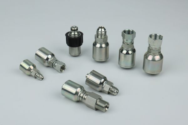
43 series Crimp Fitting

Show independent review and authorization

The report should identify the preparer, technical reviewer, approval authority, date, and report revision. Corrections must remain traceable; replacing a report without a revision trail can separate the approval from the evidence reviewed.

If the test was performed by an outside laboratory, record the laboratory report identity and scope relevant to the method. Do not claim accreditation, certification, or independence unless verified documents support the statement.

Audit Evidence Completeness Before Relying on It

A completeness matrix helps reviewers distinguish missing paperwork from evidence that cannot support the proposed claim. Every field should answer a decision question.

Use a report-field matrix

Classify missing fields as critical to identity, method, result, traceability, or administration. Missing identity, method, acceptance basis, or actual results usually prevents a technical conclusion; a minor administrative omission may be correctable without repeating the test, depending on the quality system.

Ask focused follow-up questions

Request the controlled source rather than asking for a stronger “pass” statement. Useful questions include:

If the answers cannot be documented, retain the report as incomplete evidence instead of extending its claim.

Apply the Report to a Purchasing Decision

Purchasing review should match the proposed order to the tested configuration and understand the report’s limits. A technically complete report is useful only when it applies to the product being considered.

Compare proposed and tested configurations

Check hose series, size, fitting codes, materials, end configurations, crimp process, and relevant application conditions line by line. Identify every difference and ask the responsible engineering authority whether it is within the report’s scope, supported by other evidence, or requires new validation.

Do not approve a TP-series fitting because the report tested a different series, or accept a competitor reference as proof of interchangeability. Catalog similarity can guide a search but does not replace exact configuration evidence.

Layer evidence rather than substituting it

Use component drawings and incoming inspection to evaluate fitting identity and dimensions. Use compatibility and crimp documents to control assembly. Use the test report to evaluate performance under its named method. Use application review to assess pressure, temperature, fluid, routing, vibration, and environmental conditions. None of these layers replaces the others.

Conclusion

A useful test report lets another qualified reviewer reconstruct the sample, assembly process, method, conditions, results, and approval boundary. Start with exact hose and fitting identity, then link controlled drawings, compatibility data, crimp equipment, tooling, setup, and revisions. Name the test type and record its applicable conditions without borrowing unsupported numerical values. Preserve individual results, deviations, failure observations, sample genealogy, and report authorization. Finally, compare the proposed product with the tested configuration and document every difference. A one-piece hose assembly test report supports only the scope its evidence actually covers; it cannot convert one passing sample into approval for every hose, fitting, size, process, or application.

Frequently Asked Questions

Is a pass certificate enough without the full report?

No, a certificate alone may not identify the configuration, method, conditions, results, and limitations needed for review. Request the controlled report and supporting records appropriate to the decision.

Can one test report cover several fitting sizes?

Only when the approved validation plan and technical authority explicitly define that scope. Do not assume evidence transfers across sizes merely because the fittings share a series name.

Does component inspection replace hose assembly testing?

No, component inspection can verify defined material, thread, or dimensional characteristics, while assembly testing examines the finished configuration under a named method. Both have different evidence boundaries.

Should failed or interrupted tests appear in the report?

Yes, they should be recorded with factual observations, conditions, and disposition. Omitting them can distort the evidence and prevent proper review of deviations or root cause.

Does a laboratory report guarantee field performance?

No, it reports results for specified samples and controlled conditions. Field suitability still depends on the complete system, application, installation, maintenance, and conditions outside the test scope.

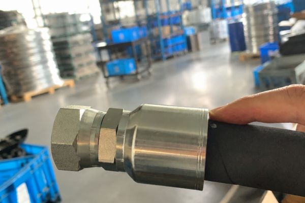
How to Measure Crimp Diameter on One-Piece Hose Fittings

How to Measure Crimp Diameter on One-Piece Hose Fittings

Two inspectors can measure the same finished ferrule and record different values when they use different locations, instrument pressure, orientations, or treatment of ridges. To measure crimp diameter on one-piece hose fittings consistently, the inspection method must define the correct measurement zone, suitable calibrated instrument, required circumferential positions, and acceptance source before anyone takes a reading. The measured value then has to be linked to the exact hose, fitting, machine setup, and approved crimp data. This is a metrology task, not a way to invent a target dimension or approve an unidentified assembly.

Start With the Governing Measurement Instruction

The first question is not which number appears on the instrument; it is which controlled document defines what to measure. A crimp diameter has meaning only when the measurement location and method match the acceptance data for the exact assembly.

crimp Fitting Assembly

Confirm the assembly identity

Record the hose manufacturer, hose series, construction, size, complete fitting code, fitting series, and ferrule design. Confirm the work traveler and the revision of the crimp specification. The same dash size does not authorize using a target or method from another hose series, fitting family, or brand combination.

Also confirm that the assembly is safe to handle. Do not measure a connected, pressurized, leaking, or otherwise hazardous assembly. Isolate the hydraulic system, release pressure and stored energy, secure raised loads, and follow the applicable equipment and component procedures before removing or inspecting field hardware.

Read the method, not just the target

Approved data may define where along the ferrule to measure, how many readings to take, whether particular orientations are required, which surfaces are excluded, and how results are evaluated. A target dimension copied without those instructions can produce a false comparison. The drawing or crimp chart may also distinguish different ferrule zones or product constructions that look similar from a distance.

If the measurement location, instrument type, or acceptance rule is missing, place the result on hold. Do not choose the smoothest area, average convenient readings, or borrow a method from a neighboring SKU to make the inspection possible.

Before measurement, confirm this minimum evidence set:

Locate the Correct Crimp Measurement Zone

Measurement location is a controlled characteristic because ferrule geometry is not necessarily uniform along its length. Readings taken near an end, transition, groove, or local feature may not represent the zone used to establish the approved crimp data.

Establish axial position from a defined reference

Use the reference identified in the applicable instruction, such as a ferrule edge, shoulder, band, or drawing-defined location. Keep the instrument contacts within the stated zone and square to the ferrule axis unless the method specifies otherwise. Marking the zone with a removable, approved method can help repeatability, but the mark must not damage the surface or obscure a defect.

Avoid measuring partly on a taper, end flare, step, raised marking, damaged patch, or coating buildup unless that feature is explicitly included in the method. Even a small axial shift can place the contacts on a different part of the crimp profile and create an apparent disagreement between inspectors.

Control the part’s condition and support

Clean loose debris only as the approved procedure permits. Do not file, polish, compress, or reshape ridges to obtain a stable reading. Support the assembly so its weight does not tilt the instrument or pull the hose against the ferrule while the reading is taken.

The hose should rest without twist or forced bending near the fitting. Inspectors should also note visible impact, cracked plating, displaced components, or other conditions that may invalidate routine measurement and require a separate disposition.

Select and Verify the Measuring Instrument

Use an instrument capable of contacting the specified surfaces and resolving the required acceptance range. Instrument choice should come from the inspection plan, measurement-system evaluation, or technical procedure—not from whichever tool is nearest.

Match contact geometry to the ferrule

Calipers may be suitable for some defined checks, while other geometries or accuracy requirements may call for a micrometer or a dedicated device. Broad, narrow, flat, or shaped contacts interact differently with crimp ridges and valleys. A tool that bridges high points can report a different functional dimension from one whose contacts fall between them.

The selected instrument must be able to reach the measurement zone without contacting the hose, fitting body, ferrule end, or adjacent feature. Do not angle the jaws to fit into a restricted area. If the required contacts cannot sit correctly, the instrument or inspection setup is unsuitable for that measurement.

Confirm instrument status and technique

Check the instrument identifier, current calibration or verification status, cleanliness, zero condition, range, resolution, and physical condition according to the local metrology system. Close the contacts with consistent measuring force. Excessive force can deflect the instrument, mark a soft surface, or create operator-dependent readings.

Before recording production results, inspectors should be able to repeat a reading on a suitable reference or training piece within the shop’s accepted method. If two instruments disagree, do not average their outputs. Isolate the issue by checking zero, condition, contact placement, method, environment, and metrology status.

Control Orientation and Circumferential Readings

A single reading can miss out-of-round geometry or exaggerate a local ridge. Follow the exact number and orientation of readings specified by the approved crimp procedure.

right Hydraulic Hoses Orientation

Keep the instrument perpendicular

Place the contacts across the ferrule with the measurement axis passing through the intended diameter. Keep the instrument square to the fitting axis and avoid rocking it diagonally. A skewed position measures a chord or diagonal rather than the required diameter and often produces a larger, unstable result.

Rotate around the ferrule only through the positions allowed by the instruction. When specific clock positions are defined, establish a repeatable reference such as the fitting orientation, machine seam, or a controlled mark. When the procedure calls for multiple evenly distributed readings, do not concentrate them on the easiest exposed side.

Record individual values before calculating anything

Write each reading as observed, with its position, before applying any specified calculation or decision rule. Do not erase the highest or lowest value because it appears inconvenient. Variation between positions can be evidence of die condition, component placement, debris, asymmetric setup, or measurement error.

Use an average, range, maximum, minimum, or other derived value only if the governing procedure requires it. A calculated average may conceal one unacceptable position when each reading has an individual limit. Conversely, rejecting solely on spread without an approved out-of-round criterion can create an unsupported decision.

Interpret Ridges, Flats, and Out-of-Round Indications

Finished crimp geometry reflects the ferrule, die segment pattern, process, and material response. Visible ridges do not tell an inspector where the approved diameter is defined, and a smooth appearance does not prove conformity.

Distinguish normal pattern from measurement interference

Segment impressions, narrow ridges, flats, or transitions may be expected for a particular controlled process, but their acceptability must come from the applicable specification or approved visual standard. Position the contacts as instructed relative to those features. Do not hunt for the lowest diameter or deliberately bridge the highest points unless the method says to do so.

Surface finish can also affect contact. Dirt, burrs, coating damage, dents, or raised marks may produce unstable readings and may represent a separate defect. Record the condition and follow the nonconformance process rather than modifying the surface or choosing another area without authorization.

Treat inconsistent diameters as a diagnostic signal

When readings differ more than expected under the approved method, first repeat the measurement with controlled placement and technique. If variation persists, hold the assembly and review instrument condition, measurement zone, die cleanliness and condition, die seating, component position, machine setup, and part identity.

Do not assume that an out-of-round indication can be corrected by recrimping. Any additional crimp operation requires explicit manufacturer or process authorization for the exact assembly. A second operation may further compress or damage the hose, ferrule, or reinforcement while hiding the original cause.

Compare Results With the Correct Acceptance Data

The right comparison is between traceable readings and the current acceptance rule for the exact controlled combination. A historical spreadsheet, handwritten value, or chart for another SKU cannot release the assembly.

Verify scope and revision

Confirm that the crimp record names or unambiguously covers the hose series, hose size, fitting family, ferrule, preparation method, machine or process basis, and applicable revision. Review any notes that modify the target by product variant or measurement location. If the shop uses electronic programs, verify that the document and program revision agree.

Classify the result using the procedure’s defined outcome: acceptable, hold for clarification, or nonconforming. Do not invent a tolerance around a target that has no published acceptance range. Likewise, do not convert an approximate setup value into a finished-product criterion.

Escalate ambiguity without losing evidence

When the source data conflict, preserve the assembly, readings, instrument identity, setup record, and documents used. Ask the responsible technical or quality authority to identify the governing revision. Do not repeatedly measure until one reading falls inside the preferred range.

If the method itself appears difficult to reproduce, raise a measurement-system concern. A process cannot be controlled reliably when inspectors use different contact points or interpretation rules. The corrective response may involve clearer drawings, a fixture, improved training, or a formal measurement-system study rather than changing the product.

For an ambiguous result, preserve:

Use a Complete Inspector Measurement Record

A useful record lets another qualified person reconstruct the measurement and determine which batch or setup it supports. Blank fields should trigger clarification rather than quiet assumptions.

Attach photographs only when the procedure needs them, and include a clear orientation or datum. A photograph of an instrument display without the contact location, assembly identity, and source data is weak evidence. Keep the record with the batch or hose-assembly genealogy defined by the quality system.

Conclusion

Consistent crimp measurement begins with the approved method for the exact hose-and-fitting combination. Confirm identity and revision, locate the drawing-defined measurement zone, use a suitable controlled instrument, keep the contacts square, and capture every required circumferential reading before calculating a result. Ridges, flats, surface damage, and out-of-round indications must be interpreted through the applicable procedure rather than personal preference. Compare observations only with current acceptance data and hold the assembly when the method, source, or instrument is uncertain. A complete record should link the values to the component lots, machine, tooling, program, instrument, inspector, and disposition. That discipline is how inspectors reliably measure crimp diameter on one-piece hose fittings without inventing a universal range.

Frequently Asked Questions

Can a caliper always be used to measure crimp diameter?

No, instrument suitability depends on the required accuracy, contact geometry, ferrule features, and approved method. Use the instrument specified or accepted by the controlling inspection procedure.

Should the smallest circumferential reading be reported?

Only if the approved method defines that decision rule. Record all required individual readings and apply the specified maximum, minimum, average, or position-based criteria without selecting a convenient value.

Can a reading be taken over a die ridge?

That depends on how the controlled method defines the contact position relative to the crimp pattern. Do not bridge or avoid ridges based on personal preference.

What should happen if two inspectors disagree?

Place the result on hold and compare assembly identity, axial location, orientation, contact force, instrument status, and method interpretation. Do not average the inspectors’ results unless the procedure explicitly requires it.

Does an acceptable diameter prove the hose was inserted correctly?

No, diameter is only one characteristic of the completed assembly. Hose identity, preparation, insertion, fitting identity, tooling, setup, condition, and other required checks still need independent confirmation.

How to Verify a Mixed-Brand Hose and Fitting Match

How to Verify a Mixed-Brand Hose and Fitting Match?

Mixing hose and one-piece fitting brands is acceptable only when an authorized technical basis covers the exact hose, stem, ferrule, preparation, crimp process, tooling, and application. Matching dash sizes, similar construction, thread fit, or a successful-looking first assembly does not establish compatibility. The approval may come from current published combination data or from a formally controlled evaluation accepted by the responsible parties, but it must define scope and accountability. Without that evidence, the combination belongs on hold.

Begin at the Compatibility Approval Boundary

The decision is not whether two components can be physically assembled. It is whether the complete combination has an approved technical basis for the intended service and process.

Name every element in the proposed combination

Record the hose manufacturer, complete hose series, construction, size, and relevant revision or lot. Record the full fitting code, stem design, retained ferrule or sleeve, fitting series, and port-end configuration. Add hose preparation, insertion method, crimp machine, die or tooling, program, measurement method, and the controlling document revisions.

The port thread and sealing interface still require separate verification, but they do not approve the hose side. A fitting can mate correctly with the equipment while being unsuitable for the selected hose construction or crimp process.

Crimp Fitting LOGO Custom

State who has authority to approve use

Identify the technical authority, hose-assembly quality system, equipment requirement, and contractual conditions that govern the combination. A salesperson’s assurance, distributor chart, old email, or operator experience may point to information, but it is not automatically an approval record.

The decision should define intended application, fluid, working and transient conditions, temperature, routing, vibration, environment, and consequences of failure. Pressure suitability is limited by the lowest-rated component and the complete assembly conditions; no brand combination creates a universal rating.

Prefer Explicit Published Combination Approval

The strongest routine evidence is current technical data that explicitly names or unambiguously covers the exact hose and fitting combination. A general statement that a product is “compatible with common hoses” is not enough.

Check document scope line by line

Confirm the issuer, document number, revision, effective status, hose series and size, fitting family and size, ferrule, preparation method, crimp equipment basis, tooling, target and acceptance method, and any restrictions. Verify that the data applies to mixed-brand use rather than to a same-brand system with similar names.

Read footnotes and exceptions. One approved size does not automatically approve adjacent sizes, and one hose construction does not authorize another. A table may also depend on a specific fitting revision, machine family, or procedure that is not available at the shop.

Distinguish approval from resemblance

Visual matching can reveal obvious conflicts but cannot establish internal stem engagement, ferrule compression, reinforcement capture, or material response. Dash size identifies a nominal size relationship; it does not prove hose OD, reinforcement, cover, tube, or crimp behavior.

Likewise, a thread that engages at the port says nothing about hose-side compatibility. A cross-reference can identify a candidate for comparison, but it must be followed by exact drawings, data, and approval. Do not turn a catalog similarity into a performance guarantee.

Lock the Hose, Stem, Ferrule, and Process Together

Compatibility belongs to a defined assembly system, not to any one component in isolation. Changing one element can change the evidence required for release.

Define the hose and fitting construction

For the hose, capture manufacturer, series, tube and reinforcement type, cover, size, and any version information used by the approval. For the fitting, capture stem geometry, ferrule design, retention method, material or finish where relevant, and complete code. A one-piece configuration reduces the chance of selecting a separate ferrule, but it does not make the retained ferrule suitable for every hose.

Do not assume two hoses with the same inside diameter or dash have the same outside diameter, reinforcement response, or compression requirement. Do not assume two fitting stems with similar serrations or length engage the hose identically.

crimp Fitting Assembly

Define the assembly process as evidence

The process package should identify cutting and cleaning requirements, skive or no-skive preparation when applicable, insertion reference, machine, die set, program or setup, crimp location, measurement instrument, measurement positions, and acceptance rule. Use the current instructions authorized for the mixed combination.

Never derive a crimp target by averaging two brands’ charts or copying the closest same-brand row. A measured diameter by itself cannot prove correct insertion, reinforcement capture, compatibility, or pressure performance.

Require a Controlled Evaluation When Published Approval Is Absent

When no published approval covers the proposed combination, routine production should not become the experiment. Any evaluation must be planned, authorized, and limited to a defined question before parts are assembled for service.

Write the evaluation scope first

The responsible technical authority should define the exact components, sizes, revisions, process, equipment, application envelope, sample plan, inspections, tests, acceptance criteria, and required records. Test methods and conditions must come from applicable requirements; they should not be invented to obtain a favorable result.

The plan should state who owns design responsibility, who performs assembly, who reviews data, who authorizes the result, and what changes require re-evaluation. It should also address safe containment, calibrated equipment, and disposition of tested components. A pressure or impulse test can be hazardous and must be performed only through qualified procedures and facilities.

The evaluation package should identify:

Avoid conclusions larger than the evidence

One assembly that crimps smoothly or survives one test does not approve a mixed-brand system. Evidence may apply only to a named hose series, size, fitting code, ferrule, machine, tooling, process revision, and defined application. Different sizes, lots, constructions, or environments may require separate consideration.

Record failures and ambiguous results as well as passing observations. Do not retest until a preferred outcome appears without investigating the cause and following the approved plan. If acceptance criteria were not established before testing, the result cannot be converted afterward into a reliable approval.

Control Accountability, Revisions, and Traceability

An approval that cannot be retrieved at the crimper is not an effective process control. The shop must connect the released combination to current work instructions and preserve who authorized it.

Create a controlled combination record

Assign an identifiable record to the exact approved combination. Link it to hose and fitting product definitions, evaluation evidence when applicable, work instructions, machine programs, inspection methods, training, and revision history. Prevent obsolete charts or screenshots from remaining at workstations.

Production records should capture hose lot, fitting lot, machine, tooling, program or setup, operator, first-piece results, and the approval revision. That genealogy lets a later problem be contained without questioning unrelated combinations.

Review changes before continued use

Changes to hose construction, supplier, series, stem, ferrule, material, finish, drawing, machine, die, software, process instruction, or test method may affect the approval basis. Route each change through the designated technical authority rather than relying on the same product name.

Document whether the previous evidence remains applicable, needs supplemental review, or is withdrawn. Communicate effective dates and affected lots so old and new configurations do not mix during transition.

Use Clear Release and Hold Criteria

The decision should be reproducible by another reviewer. “It worked before” and “the sizes match” are not release criteria.

topa logo hose

Release only within documented scope

Release the combination when current evidence identifies the exact components and process, the intended application falls within scope, tooling and instructions are available, responsibilities are accepted, and required first-piece or production controls are satisfied. State any limitations directly on the combination record and traveler.

Hold when a product identity, revision, process field, application condition, approval owner, or acceptance source is missing or conflicting. Reject the proposed path when controlled data explicitly exclude it, the combination falls outside the approved scope, or required evidence cannot be obtained.

Release requires all of the following:

Prevent emergency substitution

An equipment outage does not justify assembling an undocumented mix. Stop the equipment, isolate the hydraulic system, release pressure and stored energy, secure raised loads, and follow lockout and manufacturer procedures. Do not install a questionable assembly temporarily or check a suspected high-pressure leak by hand.

If time is critical, pursue a documented approved combination, a correctly identified replacement assembly, or authorized engineering review. Record the missing evidence so the same unsafe shortcut is not proposed at the next repair.

Complete an Evidence Request Worksheet

Use the worksheet before purchasing, assembly, or evaluation. Mark unavailable items as missing rather than assuming them.

Attach the governing documents, not only their titles. Record conflicts, open questions, reviewer, final decision, and date. The worksheet organizes evidence; it does not replace the technical documents or approval authority it references.

Evaluate the quality of each attachment before treating the worksheet as complete. A current signed or otherwise controlled technical record with defined product scope carries different weight from an undated screenshot, marketing page, translated excerpt, or email that omits the exact series. Check whether a table is normative approval data, a cross-reference for identification, or merely a sales catalog. If language has been translated, preserve the source version and confirm that size notes, exclusions, and revision information were not lost.

The final decision note should state what is approved and what is not. For example, approval of one hose size and one fitting code should not appear in the item master as approval of every size in those two families. Name the permitted machine and process basis when they are part of the evidence, and name application limits that require separate review. Link the decision to purchasing controls so an alternate component cannot be introduced under the same short description. Link it to the crimper so the operator sees the current combination record, not a detached copy. These controls keep technical scope intact as the decision moves from engineering to buying, inventory, assembly, inspection, and later repair records.

Conclusion

Mixed-brand assembly decisions require more than matching labels or a successful crimp. Define the exact hose, stem, ferrule, fitting, process, tooling, and application, then look for current published data that explicitly approves that combination. When no such approval exists, use a formally authorized evaluation with predetermined methods, criteria, responsibilities, and scope. Keep the resulting decision revision-controlled and traceable to component lots, machine setup, first-piece inspection, and production records. Hold any combination with missing identity, conflicting data, unclear ownership, or application conditions outside the evidence. Before mixing hose and one-piece fitting brands, prepare the full evidence worksheet and obtain the responsible technical approval rather than transferring assumptions from dash size, appearance, thread fit, or one test.

Frequently Asked Questions

Does matching dash size prove cross-brand compatibility?

No, dash size does not define hose construction, outside diameter, stem geometry, ferrule response, or crimp process. Approval must cover the exact component combination.

Can a correct crimp diameter validate a mixed-brand assembly?

No, the measurement confirms only one characteristic under a defined method. Identity, insertion, reinforcement engagement, process, application, and approval evidence still require verification.

Is one successful pressure test enough for approval?

No, a single result cannot establish broad compatibility. Testing must follow an authorized plan with defined samples, methods, criteria, scope, and technical acceptance.

Who should approve a mixed-brand combination?

The authority must be defined by the applicable manufacturer data, equipment requirements, quality system, contract, and design responsibility. An informal assurance should not replace that documented authority.

What happens when one component revision changes?

Route the change through the approval owner before continued use. The reviewer must decide whether existing evidence remains applicable, needs supplementation, or must be withdrawn.

Contact Topa

Save 30% on maintenance costs with our easy-install hydraulic fittings. Contact Now!