
After a hydraulic cylinder mounting eye breaks, do not approve another cylinder until the complete mount and load path have been reviewed. The failed eye, pin, bushing or bearing, spacers, brackets, cylinder geometry, rod, and machine movement work as one interface. A thicker eye or larger rod may increase one section while leaving misalignment, binding, impact, or inadequate support unchanged. Hydraulic cylinder eye failure inspection should therefore preserve fracture evidence, define the installed datums, and compare the actual machine with the released design. Support the load independently, isolate the hydraulic system, and release stored energy before anyone removes or measures the damaged cylinder. Never cycle it merely to reproduce the event.
Make the Machine Safe and Preserve the Failure Evidence
A broken mount can remove the cylinder’s ability to control a load. The first priority is independent mechanical support and an approved isolation plan, not repositioning the machine for convenient photography.
Stabilize without changing the scene unnecessarily
Qualified personnel should secure raised or suspended structures, prevent unintended movement, isolate hydraulic and other stored energy, and follow lockout requirements. Do not rely on the damaged cylinder, a control valve, or hydraulic pressure to hold the load. Do not straighten the rod, force the remaining eye into alignment, enlarge pin holes, or weld the fracture in the field.
Once the equipment is stable, document the cylinder position, machine configuration, load condition, pin and bracket arrangement, hose condition, and any displaced components before removal. Record what was observed, what was reported by operators, and what remains unknown. A post-event position is not necessarily the position in which the fracture began.
Protect the fracture and related parts
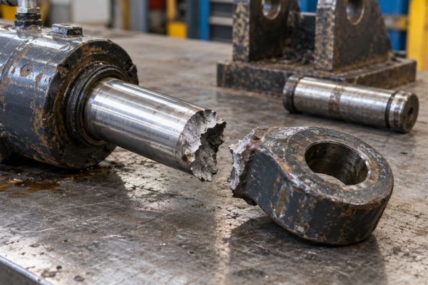
Preserve both sides of the broken eye when available. Do not grind, clean aggressively, paint, fit the pieces together repeatedly, or mark the fracture face. Package the eye, pin, bushing, spacers, retainers, and relevant fasteners separately with traceable labels so contact damage is not mistaken for original evidence.
Photograph the fracture at several scales, plus the eye bore, weld or transition region, rod, gland, pin, bracket faces, stops, and nearby contact marks. Material or fracture analysis may later require controlled samples, but appearance alone should not be used to declare fatigue, overload, bad welding, misuse, or a manufacturing defect.
Reconstruct the Sequence Without Treating It as Proven
An eye fracture and a bent rod may occur in the same event, but their order is not self-evident. The investigation should develop competing sequences and test them against physical, operational, and control-system evidence.
Build an event timeline
Collect operator observations, maintenance history, control commands, load state, machine position, previous looseness or noise, earlier repairs, and any available data logs. Distinguish firsthand observations from later interpretation. “The rod appeared bent after the eye broke” is evidence; “the eye broke first and caused the bend” is a hypothesis.
Map external marks and deformation. Contact at a bracket edge, polished pin surface, displaced spacer, bent retainer, rod scoring, or end-of-stroke damage can identify where loads acted, but each mark needs geometric context. Avoid cycling the failed assembly to see which component touches; use drawings, stable mock-up methods, or approved engineering analysis instead.
Keep hydraulic and structural questions separate
Pressure history may help evaluate cylinder force, shock loading, or circuit behavior, but a pressure test does not prove mount alignment, fatigue life, weld quality, or correct machine geometry. Likewise, a sound eye material result does not show that the pin and bracket allowed the intended movement.
Review whether the cylinder could reach an internal end stop before the machine reached its mechanical stop, whether the mount could bind through the motion, and whether control or cushion behavior could create impact. These are design and application questions. They should not be collapsed into a single “cylinder passed pressure” statement.
Inspect the Pin, Eye, Bearing, Spacers, and Bracket Together
The mounting eye does not carry load alone. Load enters through the pin and contact interface, passes through the eye and cylinder structure, and reacts through the opposite mount and machine brackets.
Check the complete joint condition
Identify the specified pin diameter, eye bore, bushing or spherical bearing, bracket width, spacer arrangement, retainer, lubrication condition, and allowed movement. Inspect for wear steps, fretting, galling, corrosion, ovality, edge loading, seized components, missing spacers, displaced retainers, and witness marks. Use controlled measurements rather than inferring fit from looseness by hand.
A plain bushing, spherical bearing, and direct pin bore accommodate different movement and loading. Do not substitute one model’s clearance or articulation expectation for another. An apparently loose pin may be within a specified fit, while a tight joint can still be wrong if it prevents the angular movement required by the machine.
Bracket geometry controls how the eye is loaded
Measure bracket face condition, spacing, parallelism, coaxiality, pin support, and deformation from defined datums. A narrow bracket can clamp the eye or bearing; excessive space can allow impact unless the design controls lateral position. A bent ear or noncoaxial hole can force the pin to bend and load only one side of the eye.
Record the assembled stack rather than measuring loose parts only:
- left bracket ear, spacer, eye or bearing, spacer, and right ear;
- pin support and retention at both ends;
- axial movement permitted by the design;
- angular movement required through the machine cycle; and
- contact marks showing actual load concentration.
Distinguish Pin Clearance From Mount Misalignment
Clearance permits assembly and movement; misalignment changes the load path. A pin can enter both holes and still be subjected to bending, edge contact, or angular load when the cylinder moves.
Positional and angular errors are different
Positional misalignment exists when mount axes do not occupy their intended locations. Angular misalignment exists when their axes are not parallel or when the cylinder line of action changes relative to the joint. Pin clearance may temporarily mask either condition during assembly, but it does not remove the resulting side load.
Inspect both cylinder mounts and the driven structure. A correctly machined rod-end eye can be forced out of line by a distorted base bracket, incorrect spacer, welded ear position, worn pivot elsewhere, or machine frame deformation. Keep port orientation separate: hose-port direction affects routing and service access, while mount-axis alignment governs the structural motion addressed here.
Observe the permitted motion safely
Engineering should define the range of angles and translations the joint must accommodate. Use measurements, CAD, fixtures, or another approved method that does not require operating the damaged cylinder. If a replacement sample is later installed for controlled verification, support conditions and stop positions must represent the machine while keeping personnel clear of the load path.
Do not use the pin or hydraulic force to pull brackets into alignment. Forced assembly stores load before the cylinder begins working and can create an early fracture, bearing wear, rod side load, or seal damage even if the machine initially moves.
Define Datums and Inspection Conditions
Measurements taken with the cylinder lying unsupported on a bench may not represent its installed axis. The review must state the support points, cylinder position, extension, and datums used.
Use reproducible geometry
Typical references may include the cap-end and rod-end pin axes, barrel axis, rod axis, machined mounting faces, bracket-hole axes, and machine-frame datums. Engineering must select the applicable ones from the released design. Do not define “vertical” from a photograph or shop floor unless verticality is actually a controlled requirement.
Record pin-to-pin length at the specified position, stroke, retracted and extended lengths, eye orientation, bracket spacing, pin locations, rod runout or straightness method, and the relationship between cylinder and machine motion. If gravity causes an unsupported rod to sag during measurement, use the approved support arrangement and include its effect in the method.
Compare the actual installation with the design
Measure both the failed cylinder and machine interface when possible. A cylinder can conform to its drawing yet be unsuitable for an altered or damaged machine; a machine can match its drawing while the supplied cylinder deviates. The evidence should separate these possibilities before assigning responsibility.
Useful comparisons include:
- actual and specified mount-axis positions;
- pin, bore, bearing, and bracket-stack dimensions;
- cylinder length and stroke relative to machine stops;
- available articulation versus required articulation;
- rod and barrel alignment under the defined support condition; and
- interference or edge contact throughout the intended motion.
Do Not Treat a Larger Rod or Thicker Eye as a Complete Fix
Increasing a component section changes only part of the system. It can also alter stiffness, mass, clearances, weld geometry, bearing space, force area, and how load transfers to adjacent parts.
Rod hardness is not bending capacity
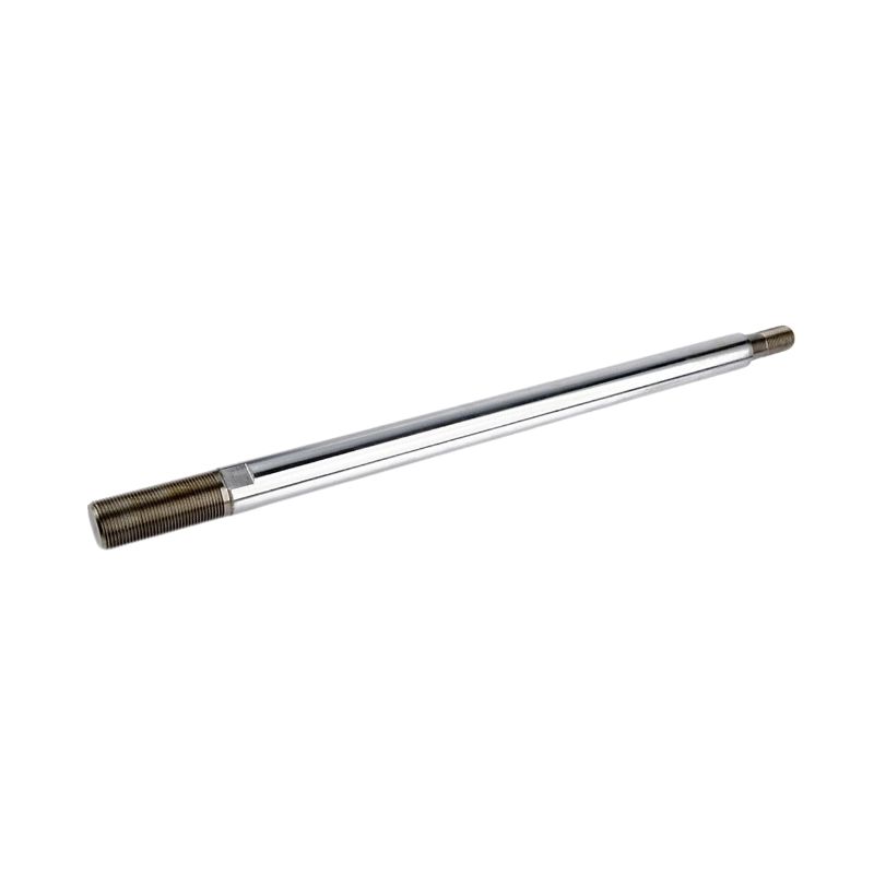
Surface hardness or coating can improve resistance to wear, scoring, or indentation under applicable conditions. It does not by itself define the rod’s resistance to bending or buckling. Structural capacity depends on rod diameter, material properties through the section, unsupported length, end conditions, load direction, alignment, dynamic impact, and safety factors established by engineering.
A harder rod can still bend under excessive compression or side load, and increasing diameter does not correct a binding mount. It may transfer greater load to the eye, pin, bracket, barrel, or machine frame. Do not straighten a bent rod for service without an approved repair procedure and complete dimensional and surface evaluation.
Eye reinforcement must follow the load path
A thicker eye or larger transition radius may reduce local stress in one geometry, but it needs drawing control, material and process review, clearance confirmation, and structural validation. Field welding can introduce heat effects, distortion, cracks, altered alignment, and unverified penetration. It must not be recommended as an improvised response to a fracture.
Review the surrounding bracket and pin before strengthening the eye. If load is concentrated at one edge because the pin axes are misaligned, a stronger eye may simply delay failure or move it elsewhere. A correction is credible only when the modeled and measured interface supports the intended movement and loading.
Decide Whether the Problem Is Deviation or Redesign
A production deviation means the delivered cylinder or mount does not meet the released requirement. A redesign is needed when conforming components cannot perform reliably in the actual application or when the requirement fails to describe the necessary interface.
Establish conformity first
Compare the failed cylinder, retained samples, and machine geometry with controlled drawings and revisions. Review material, weld, machining, heat-treatment, assembly, and inspection evidence relevant to the observed feature. Do not treat missing records as proof of defect, but do not claim conformity where verification is absent.
If a dimension, bearing arrangement, load case, or permitted articulation was never specified, the issue may require an engineering requirement rather than a supplier sorting rule. General tolerances should not be applied to unmarked functional geometry without confirming the drawing convention and contractual design basis.
Validate before repeat-order approval
The approval package should connect the corrected drawing to the real machine interface. It may require dimensional inspection, material or weld verification, controlled assembly, motion and clearance review, structural analysis, and application-specific validation. Pressure testing addresses containment under its defined conditions; it does not validate mount fatigue life or installation alignment.
Prepare the following cylinder-and-mount information:
- cylinder drawing, revision, type, bore, rod, stroke, and pin-to-pin dimensions;
- eye, bearing or bushing, pin, spacer, retainer, and bracket details;
- machine datums, mount-axis locations, stops, motion, and installation photos;
- actual load direction, duty, shock conditions, pressure history, and environment;
- fracture, rod, contact-mark, and dimensional evidence with traceability;
- material, weld, machining, and inspection records relevant to the hypotheses; and
- approved correction, validation plan, results, and change-control requirements.
Conclusion
A broken cylinder eye is evidence of a failed structural event, not a complete diagnosis. Make the machine safe, preserve the fracture and related hardware, and reconstruct the sequence without assuming whether the eye fracture or rod bending came first. Inspect the pin, bearing or bushing, spacers, retainers, bracket, opposite mount, rod, and machine geometry as one load path. Define datums and support conditions so alignment measurements can be reproduced. A larger rod, harder surface, thicker eye, or pressure test cannot correct or validate a misaligned mounting interface by itself. Before repeat-order approval, separate production deviation from a design requirement, document the actual operating and mounting conditions, and validate the corrected hydraulic cylinder and mount together under an approved engineering plan.
Frequently Asked Questions
Does a bent rod prove that side loading caused the eye fracture?
No. It is important evidence, but the sequence and mechanism require geometry, fracture, load, contact-mark, and operating records before a cause can be assigned.
Can a larger rod prevent another mounting eye failure?
Not by itself. Rod diameter may affect structural capacity, but it does not correct pin binding, bracket misalignment, inadequate articulation, impact, or an incorrect load path.
Does a pin that slides through both brackets prove alignment?
No. Clearance can permit insertion despite positional or angular misalignment. Inspect the axes, bracket faces, assembled stack, articulation, and contact through the intended motion.
Is a pressure test enough to approve the replacement cylinder?
No. A pressure test addresses the conditions and characteristics defined by that test, not mount alignment, structural fatigue, machine interference, or long-term application loading.
May the broken eye be welded back onto the cylinder?
Only under a qualified, approved engineering repair procedure that covers material, welding, alignment, inspection, and validation. Improvised field welding can create new structural and dimensional risks.