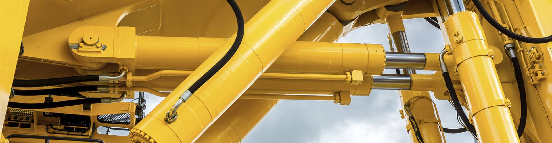
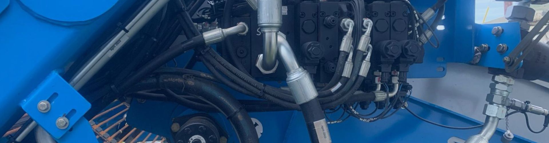
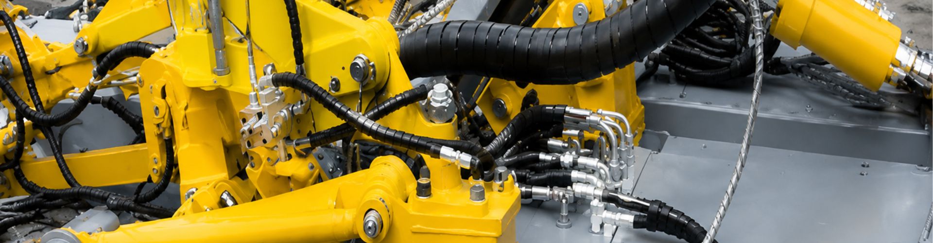
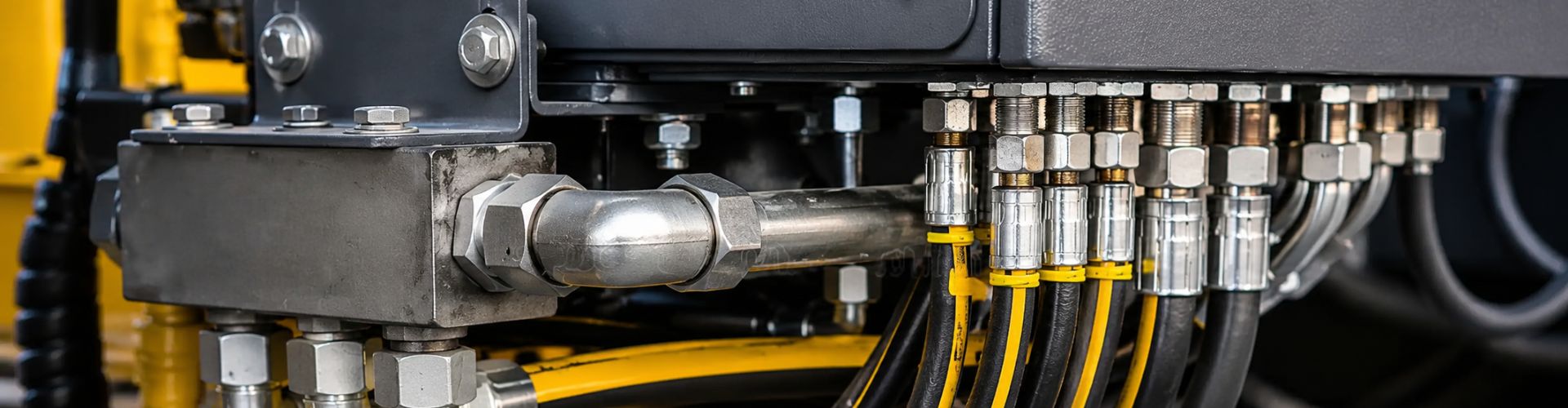
How Do You Correctly Interpret Hydraulic Fitting Pressure Ratings

How Do You Interpret Hydraulic Fitting Pressure Ratings?

You pick a fitting with a 5,000 PSI rating, assuming it’s safe for your 4,500 PSI system. But a sudden pressure spike causes a catastrophic failure, spraying hot oil and halting your operation.

Hydraulic fitting pressure ratings are classified by a combination of the fitting’s design standard (like ORFS, JIC, DIN), its size, and its material. The published rating is the Maximum Allowable Working Pressure (MAWP), which is the burst pressure divided by a 4:1 safety factor.

What is the Fundamental Principle Behind a Pressure Rating?

You see a pressure rating stamped on a fitting, but what does it truly represent? Is it the absolute maximum pressure the fitting can ever withstand before it breaks?

No, the number you see is the Maximum Allowable Working Pressure (MAWP). It’s a safe, continuous operating limit. The actual burst pressure is much higher, typically four times the MAWP, to account for real-world pressure spikes, vibration, and temperature changes.

This is the most important concept to grasp. A hydraulic fitting is not like a chain that breaks the instant you exceed its load limit. It’s an engineered component with a built-in safety buffer. This buffer is called the Safety Factor (SF).

Understanding the 4:1 Safety Factor

The industry standard for dynamic hydraulic systems—systems where pressures change, valves open and close, and loads move—is a 4:1 safety factor. The formula is simple:

Burst Pressure / Safety Factor = Maximum Allowable Working Pressure (MAWP)

This means if a fitting has a published MAWP of 5,000 PSI, the manufacturer has tested it and guarantees that it will not burst until at least 20,000 PSI.

Why Is Such a Large Safety Factor Necessary?

A 4:1 ratio might seem excessive, but it is essential for safety and reliability. Hydraulic systems are not static. The safety factor is there to absorb the energy from:

The 4:1 safety factor ensures that even with all these real-world stresses, the fitting will operate reliably for its entire service life.

How Do Different Fitting Standards Determine Ratings?

You have two fittings that are the same size, but one is a JIC fitting and the other is an ORFS fitting. Why is one rated for significantly higher pressure than the other?

The pressure rating is directly tied to the fitting’s sealing mechanism. An O-Ring Face Seal (ORFS) fitting creates a highly contained, robust seal suitable for extreme pressures, while a tapered pipe thread (NPT) fitting relies on thread deformation and is rated for much lower pressures.

JIC vs NPT vs BSP

The design standard is the single biggest factor influencing a fitting’s pressure rating. How a fitting creates a seal dictates how well it can contain high pressure without leaking or failing. As a supplier, this is one of the first things we clarify with a customer.

A Comparison of Common Fitting Sealing Designs

Let’s look at how the most common standards are designed and how that affects their ability to handle pressure.

Why a Better Seal Equals a Higher Rating

The O-Ring Face Seal (ORFS) fitting is a perfect example of design driving performance. The seal is not made by the threads at all. The threads simply provide the clamping force to press two flat faces together, compressing a soft O-ring in a groove. This creates a seal that is incredibly resistant to vibration and can handle very high pressures.

In contrast, a National Pipe Taper (NPT) fitting creates a seal by having the tapered threads of the male and female fittings literally crush into each other. This metal-on-metal deformation seal is prone to leakage without a sealant like PTFE tape and is not structurally sound enough for high-pressure hydraulic applications. This is a mistake I often see with buyers who are new to hydraulics; they try to adapt lower-pressure pipe fittings for high-pressure systems, which is extremely dangerous.

Why Does Fitting Size Dramatically Change the Pressure Rating?

You successfully used a 1/4 inch JIC fitting in a 5,000 PSI system. So you assume that a larger 1 inch JIC fitting made of the same material will also be safe at 5,000 PSI. This is a common and dangerous misunderstanding.

As a fitting’s diameter increases, so does the surface area that the pressure acts upon. To prevent failure, the maximum allowable working pressure must be decreased for larger sizes of the same fitting style to maintain the required 4:1 safety factor.

This inverse relationship between size and pressure rating is a fundamental principle of physics, but it often catches people by surprise. The reason is simple: Force equals Pressure multiplied by Area (F = P x A).

The Physics of Pressure and Size

Imagine the fluid inside a hydraulic hose. The pressure (PSI, or pounds per square inch) is pushing outwards on every square inch of the interior surface.

To keep the fitting safe, manufacturers must “de-rate” the allowable pressure as the size goes up.

Example Pressure Ratings by Size (JIC 37° Flare – Steel)

Every fitting catalog, including ours at Topa, includes a chart that shows this relationship clearly. Here is an illustrative example for a common JIC steel fitting.

This is why, when a client sends an inquiry for a list of fittings, we don’t just check the thread type. We check the size and cross-reference it with their stated operating pressure to ensure every single fitting on their list is correctly rated for the job.

How Critically Do Material Choices Affect the Pressure Rating?

You see three identical fittings, but one is made of brass, one of carbon steel, and one of stainless steel. Does the material they are made from change how much pressure they can safely handle?

Yes, the material is a critical factor. Carbon steel is the standard for high-pressure hydraulics due to its high strength and cost-effectiveness. Stainless steel offers corrosion resistance with comparable strength, while brass has much lower strength and is only suitable for low-pressure applications.

Brass vs stainless steel fitting

The strength of the material, specifically its tensile strength (the ability to resist being pulled apart), directly impacts the pressure rating. Choosing the right material is a balance of strength requirements, environmental corrosion, and cost.

Comparing the Big Three Materials

How Do Invisible Pressure Spikes Affect Your Fittings?

Your system’s pressure gauge always reads a steady 3,000 PSI, well below your fittings’ 4,000 PSI rating. Yet, after some time, a fitting develops a leak or fails. Why does this happen?

The gauge only shows the average pressure. Your system experiences invisible, instantaneous pressure spikes (hydraulic shock) that can be double or triple the working pressure. The fitting’s 4:1 safety factor is specifically designed to withstand thousands of these spikes over its lifetime.

This is a concept that is critical for anyone in maintenance or equipment design to understand. Static pressure is easy to manage; it’s the dynamic forces that wear a system down.

What Causes Hydraulic Shock?

Hydraulic shock, sometimes called water hammer, happens when a moving column of hydraulic fluid is forced to stop or change direction suddenly. Think about the momentum of that incompressible fluid. That energy has to go somewhere, and it converts into a high-pressure shockwave that travels through the system at the speed of sound. Common causes include:

The Role of the Safety Factor and Fitting Type

A failure due to pressure spikes is a fatigue failure. The fitting doesn’t break on the first spike. It breaks after being subjected to thousands or millions of these high-stress cycles. This is precisely why the 4:1 safety factor exists. It keeps the stress from each spike well below the material’s ultimate failure point, allowing it to survive for years of service.

This is also where premium fitting designs show their value. The O-ring in an ORFS fitting acts as a small cushion and creates a seal that is extremely resistant to being loosened by these repeated shockwaves, making it the preferred choice for systems with high cyclic rates and shock potential.

What Is the “Weakest Link” Rule for Your Hydraulic Assembly?

You have meticulously selected a high-quality hose rated for 6,000 PSI and robust fittings rated for 6,000 PSI. You assume the complete hose assembly is now rated for 6,000 PSI. Is this assumption correct?

Not necessarily. A hydraulic system’s maximum pressure is always dictated by its single lowest-rated component. You must check the rating of the hose, and every single fitting and adapter in the line. The lowest number is the true MAWP of the assembly.

This is the final and most crucial check that must be performed when designing or repairing any hydraulic system. It’s a simple rule, but it is frequently overlooked, especially when adapters are involved.

An Example of the Weakest Link Rule in Action

Let’s build a common hydraulic line and see how this works.

In this scenario, many people would assume the system is safe to 5,000 PSI. This is incorrect. The entire assembly, from the hose to the final connection, has a Maximum Allowable Working Pressure of **4,000 PSI**. Running this system at 4,500 PSI would mean you are operating without an adequate safety factor, risking a premature failure at the elbow fitting.

Our Commitment as Your Supplier

This is why our team at Topa is trained to be so detail-oriented. When we get an order from a customer, we don’t just see a list of part numbers. We see a system. We help our clients by reviewing their lists and pointing out potential rating mismatches. Our goal is not just to sell fittings; it is to provide our clients with safe, reliable hydraulic systems that last. This commitment to detail is what turns a simple transaction into a long-term partnership.

Engineer’s Guide 7 Hydraulic Cylinder Design Red Flags banner

Engineer’s Guide: 7 Hydraulic Cylinder Design Red Flags

Hydraulic cylinder, as a modern industrial equipment in the indispensable power core, its performance is directly related to the performance of the whole set of equipment operating efficiency and safety. It is like a mechanical system of “muscle”, the hydraulic energy is accurately converted into a powerful linear reciprocating or oscillating motion. However, it is this seemingly mature components, in the design process but all over the “minefield”. Any negligence on the part of engineers, any seemingly minor design flaws, may be infinitely enlarged in the actual application, leading to substandard equipment performance, frequent failures, or triggering catastrophic equipment damage, production stagnation, and even jeopardize the safety of personnel.

Taboo 1: Ignoring Working Conditions – Blind Parameter Selection

This is one of the most common and fatal mistakes in hydraulic cylinder design. Many engineers rely on past experience or incomplete customer input to make quick decisions on parameters, laying the groundwork for a chain of future problems. A hydraulic cylinder does not function in isolation — it operates under specific equipment and working conditions. Failing to conduct a thorough investigation into its environment, load characteristics, and motion requirements is like “feeling an elephant in the dark.”

Risks of Inadequate Load Characteristic Analysis (Static/Dynamic/Impact)

The loads a hydraulic cylinder faces during operation are often complex and variable. Are they steady and static, or frequently changing and dynamic? Are there sudden impact loads? These factors directly influence the selection of cylinder bore, rod diameter, and the verification of structural strength. Designing based only on a “rated thrust” value while ignoring the possibility of impact forces — which may be several times higher during startup, stopping, or abrupt load changes — can easily lead to piston rod bending, cylinder tube expansion, or even failure of connecting components. For instance, in a punching press application, the impact force at the moment of operation is much greater than during smooth extension.

Hydraulic Cylinder in mining

Chain Reactions from Mismatched Speed and Stroke

Cylinder speed and effective stroke are two other critical parameters. If high-speed operation is required but the system’s oil supply capacity, port size, and cushioning needs are not adequately considered, excessive pressure losses, unstable motion, excessive noise, or failure to reach the target speed due to insufficient flow may occur. Conversely, for low-speed requirements, using large-diameter ports and valve groups may reduce control precision and unnecessarily raise costs. On the stroke side, overlooking installation space, buckling risks for long-stroke cylinders, or the need for end-of-stroke cushioning and limit stops can result in installation challenges, operational interference, impact damage, or instability.

Fatal Impacts of Environmental Factors

The working environment has a critical impact on the cylinder’s service life and reliability. High temperatures can accelerate seal aging, reduce hydraulic oil viscosity, and even affect the mechanical properties of metal components. Low temperatures may cause seals to harden and hydraulic oil to become too viscous. In dusty environments like mining sites or cement plants, if effective dust protection (e.g., wiper seals, rod covers) is not in place, abrasive particles can easily enter the cylinder, scratch the piston rod and cylinder bore, damage seals, and lead to serious internal or external leakage. Corrosive environments, such as chemical plants or offshore platforms, place strict demands on the corrosion resistance of cylinder materials, piston rods, and seals. Ignoring these factors and using generic cylinders often results in premature failure and frequent maintenance.

Taboo 2: Improper Material Selection – Compromised Strength and Durability

Material selection is the foundation of a hydraulic cylinder’s load-bearing capacity, service life, and environmental adaptability. If the investigation of working conditions is the “diagnosis,” then material selection is the “prescription.” Once the wrong materials are chosen, even the most sophisticated structural design cannot ensure stable and reliable performance under harsh conditions. Strength and durability will be severely compromised, potentially leading to safety incidents.

Risk of Instability Due to Insufficient Strength in Cylinder Tube and Piston Rod Materials

The cylinder tube and piston rod are the primary load-bearing components of a hydraulic cylinder. The tube must withstand high internal pressure, so the selected material must meet the required yield strength and tensile strength under design conditions, along with an appropriate safety factor. If the cylinder tube’s strength is insufficient, it may undergo permanent plastic deformation (bulging) under pressure, leading to increased internal leakage, reduced efficiency, or, in extreme cases, catastrophic rupture.

The piston rod mainly bears axial compression or tension. Its material must not only be strong but also offer adequate stability against buckling under compression. This is especially critical for long-stroke cylinders with relatively small rod diameters. If the rod material has a low elastic modulus or insufficient yield strength, it is highly susceptible to bending and instability under load, resulting in jamming, seal damage, or rod fracture.

Seal Material Incompatibility with Hydraulic Fluids and Operating Conditions

Seals may seem fragile compared to metal components, but they are vital to cylinder performance. Seal materials must be fully compatible with the hydraulic fluid (including oil type and additives), operating temperature range, motion speed, and external environment (such as exposure to chemicals or abrasives). Incompatibility can lead to swelling, hardening, cracking, or chemical degradation of the seals, causing rapid failure.

For instance, Nitrile rubber (NBR) seals may deteriorate quickly when exposed to certain synthetic hydraulic fluids or high-temperature environments. Fluorocarbon rubber (FKM/Viton®) offers excellent resistance to heat and oils but can become brittle in cold temperatures and may degrade when exposed to specific media such as amines. Choosing “universal” seal materials without assessing compatibility is a common reason for early hydraulic cylinder leakage.

Overlooking Special Material Requirements in Harsh Environments

Beyond basic strength and wear resistance, special working conditions demand more stringent material performance. In the chemical industry, hydraulic cylinders may come into contact with corrosive substances like strong acids, alkalis, or organic solvents. In such cases, standard carbon steel or low-alloy steel is inadequate. Materials such as stainless steel (e.g., 316L, duplex stainless), Hastelloy, or Monel alloys may be required for cylinder tubes, piston rods, and fittings to withstand corrosion.

Surface treatments for piston rods are also critical. While hard chrome plating is common, more corrosion- and wear-resistant options like nickel-based alloy coatings or ceramic coatings may be necessary in extreme environments. Ignoring these requirements often results in premature failure, frequent maintenance, and elevated replacement costs.

Note: This table is a general recommendation, the specific value of the safety factor should be combined with the relevant standards, the severity of the working conditions, the severity of the consequences of failure, material reliability, and the internal norms of the enterprise to determine the synthesis.

Taboo 3: Structural Design Flaws – Hidden Hazards from Stress Concentration

The structural design of a hydraulic cylinder is where material properties are translated into actual load-bearing performance. Any flaws in the design—especially at critical locations involving improper shapes, abrupt dimensional transitions, or poor connection methods—can lead to stress concentration. This is like a tiny ant hole in a strong dam: it may appear minor but can eventually cause fatigue cracks or insufficient static strength, posing a serious threat to equipment safety.

Structural Weaknesses in Critical Areas

Key structural weak points often lie in the load transmission zones, such as the rod end connections (e.g., threads, clevises, and eye mounts) and the junctions between the cylinder barrel and end caps (e.g., flange connections, threaded joints, tie-rod assemblies). These areas are subject to high stress and are inherently vulnerable.

For instance, the root of a threaded rod end, the edge of a clevis pin hole, or the area around flange bolt holes are all classic stress concentration zones. If the transition radii are too small or absent, the wall thickness is insufficient, or the fasteners (like bolts) are poorly selected or arranged, localized stress can significantly exceed the average design stress. Under dynamic or impact loads, these stress points can become the origin of fatigue cracks that eventually lead to fractures and system failure.

Hydraulic Cylinder Design Red Flags

Risks from Poorly Matched Welding Design and Techniques

Welding is a common method used in cylinder fabrication—for example, welding ports to the barrel or welding certain end caps to the cylinder. However, welded joints are inherently discontinuous and prone to stress concentration and microstructural changes. If the welded structure is poorly designed—such as placing the weld seam in a high-stress zone, using undersized weld beads, or neglecting weld deformation and residual stress—the strength and fatigue life of the joint are greatly reduced.

The situation becomes even riskier if the selected materials have poor weldability or if the welding process parameters are not well controlled (e.g., inadequate preheating, improper post-weld heat treatment). Common weld defects such as cracks, lack of fusion, porosity, and slag inclusion can propagate quickly under service loads, leading to catastrophic failure.

Taboo 4: Insufficient Guidance and Support – Piston Rod “Eccentric Instability”

The guiding system of a hydraulic cylinder plays a critical role in ensuring the piston rod moves accurately and smoothly within the cylinder barrel while also bearing any side loads that may act on the rod. When guidance and support are inadequate, the piston rod can become misaligned during movement, leading to uneven wear, premature seal failure due to one-sided loading, and in severe cases, buckling under compressive force during the return stroke — a failure that can be catastrophic.

Improper Guide Bushing Length and Material Selection

The guide bushing — typically installed in the rod-end cap — is the main component responsible for guiding the piston rod. Its length (guide length) and material are key design parameters. If the guide length is too short, the piston rod will have poor alignment accuracy and reduced resistance to overturning moments, making it prone to wobbling under side loads. Generally, the ratio of guide length to piston rod diameter should meet specific design standards and be verified based on stroke length and applied forces.

Material selection for the guide bushing is equally important. The bushing must offer excellent wear resistance, a low coefficient of friction, and sufficient strength and rigidity. Common materials include bronze, cast iron, and filled PTFE (polytetrafluoroethylene). If the selected material lacks wear resistance or the fit between the bushing and rod is too loose, guiding accuracy will suffer, leading to premature wear and reduced service life.

Ignoring the Need for Intermediate Support in Long-Stroke Cylinders

In hydraulic cylinders with exceptionally long strokes — where the stroke-to-rod diameter ratio exceeds a critical threshold (often 10:1 or more, depending on operating conditions) — relying solely on the rod-end guide bushing is often insufficient to maintain stability throughout the entire stroke. When the piston rod is fully extended, its own weight and any slight initial curvature can lead to instability under compressive loads.

To mitigate this risk, the potential for buckling must be carefully evaluated during design. If necessary, intermediate support structures should be incorporated. These may be fixed supports (where space permits) or dynamic supports like floating rings that move with the rod. Overlooking this requirement and extending the stroke length without adding proper support is a common cause of instability and damage in long-stroke cylinders.

Neglecting Side Loads – The Hidden Culprit Behind Early Wear and Instability

In theory, a hydraulic cylinder’s piston rod should only experience axial loads. In practice, however, due to installation misalignment, deviations in load paths, or the structural characteristics of the equipment, piston rods often endure some degree of side loading. If these side loads are underestimated or ignored during the design phase — without verifying the load capacity of guide components (like guide bushings and wear rings) or applying measures to reduce lateral forces (e.g., using floating couplings or spherical bearings) — the result can be destructive.

Side loads generate abnormal contact stresses and wear between the piston rod, guide bushing, piston, and the cylinder’s internal surface. Over time, this not only causes leakage but also increases the clearance between components, further reducing rod stability. Ultimately, under the combined effect of axial and lateral forces, the rod may buckle and fail, posing serious reliability and safety issues.

Taboo 5: Poor Cushioning Design – When Impact Hits “Metal to Metal”

When a hydraulic cylinder drives a load at high speed and reaches the end of its stroke without effective deceleration measures, the piston collides directly with the end cap. This metal-to-metal impact creates intense shock and noise. Such uncontrolled collisions not only damage the cylinder itself (including the end cap, piston, and seals) but may also transmit destructive force to the entire machine structure. The result: reduced service life, potential system failures, and serious safety hazards.

Risks of Missing or Inadequate Cushioning

One of the most common — and dangerous — mistakes is omitting a cushioning mechanism altogether in cylinders used for high-speed motion or with high-load inertia. This is often found in low-cost systems or designs by less experienced engineers. The consequences are immediate and severe: extreme mechanical and hydraulic shock at the stroke end, loud noise, violent vibration, and long-term damage.

Common effects include:

A less obvious but equally harmful issue is insufficient cushioning. Even if a cushion is included, it may not be capable of absorbing the kinetic energy of the moving parts. This often stems from undersized cushion chambers, improperly sized orifices, or miscalculated inertia and terminal speed. In these cases, the piston still slams into the end cap, just slightly softened — leading to progressive wear and premature failure.

Mismatched Cushioning Types: Fixed vs. Adjustable Cushions

Hydraulic cylinders typically use two types of cushioning: fixed and adjustable.

Failure to match the cushion type with the actual working environment is a frequent oversight. For instance, choosing a fixed cushion in a system with frequent load or speed changes may lead to unstable operation and poor energy absorption at stroke ends. To achieve optimal performance and safety, the cushion design must reflect both the expected dynamics and any variability in the application.

Taboo 6: Missing or Improper Air Bleed Design – Trapped Air Compromises System Performance

Air trapped inside a hydraulic system is a hidden menace. It can originate from dissolved gases in the hydraulic fluid, air drawn in through leaks, or residual air left in the lines after maintenance. If air accumulates inside a hydraulic cylinder — the key actuator in the system — and is not effectively expelled, it can lead to a host of operational problems. These include erratic motion, inconsistent speed, poor positioning accuracy, increased noise and vibration, accelerated oil oxidation, and in extreme cases, seal failure due to the “diesel effect.”

Hazards of Unpurged Air Inside the Cylinder

Air is significantly more compressible than hydraulic oil. When gas bubbles are present in the cylinder chamber, they compress under pressure. As the system pressure changes or reverses direction, these bubbles expand again. This compress-and-expand cycle creates fluctuations in the effective working volume of the cylinder, disrupting smooth piston motion. The result? Jerky movements, slow-speed crawling, and unstable stroke transitions.

In addition, when bubbles collapse within the fluid or pass through high-pressure orifices, they produce high-pitched noise and vibration. Over time, the presence of air reduces the stiffness of the hydraulic system, causing slower response and reduced control precision — unacceptable in applications requiring smooth operation or accurate positioning. For these precision-critical systems, internal air must be eliminated completely.

Hydraulic Cylinder air bleed Design

Common Mistakes in Air Bleed Valve Placement and Design

Even when designers understand the importance of venting air, mistakes in the positioning and selection of bleed valves are common. The most critical factor is placement. Air naturally collects at high points or stagnant corners of the hydraulic flow path. If air bleed valves are not located at these points, their effectiveness is severely compromised.

Poor positioning leads to incomplete air evacuation, resulting in persistent system instability.

The type of bleed valve also matters:

Taboo 7: Inadequate Overpressure Protection – When the System “Runs Wild”

Hydraulic overpressure—also known as pressure surge or hydraulic shock—is a dangerous, high-intensity spike in system pressure caused by sudden changes in flow. These events often occur when valves close abruptly, cylinders reach the end of their stroke at high speeds, or external shocks affect the system. If not properly managed, these pressure peaks can far exceed normal working limits within milliseconds. The consequences range from damaged gauges and sensors to ruptured hoses, burst cylinders, and catastrophic failure that poses serious safety risks.

Causes and Consequences of Hydraulic Overpressure

Hydraulic surges typically stem from the following scenarios:

The consequences of these surges are far-reaching: They can damage the cylinder structure, burst hoses, fatigue seals, destroy sensors, or even eject end caps violently. Beyond mechanical damage, surges lead to fluid leaks, shortened component lifespan, reduced system efficiency, and dangerous, chain-reaction failures.

Cylinder Pressure Design and Testing Shortcomings

As a pressure-bearing component, the hydraulic cylinder must be capable of withstanding not only its rated operating pressure but also occasional pressure peaks. This includes:

However, in many designs, the focus remains on static pressure ratings. Engineers may underestimate surge peaks or use overly conservative designs that fail under real-world loads. Inadequate pressure ratings, weak materials, or thin wall sections are common failure triggers.

Additionally, pressure and burst testing during manufacturing is critical. If testing pressure is too low or the method is not standardized, defects in design or assembly may remain hidden until the product is in service—when failure becomes dangerous and costly.

Conclusion

We encourage you to carefully review each design taboo and recommendation discussed in this article. Reflect on your own project experience: Which of these issues have you encountered before? Which risks should you be especially vigilant about in future applications?

If you found this guide helpful for yourself or your engineering team, we invite you to share it. Should you have any custom hydraulic cylinder requirements, feel free to contact us anytime. Our expert team is ready to provide you with tailored technical support and reliable solutions.


FAQ

What causes overpressure in a hydraulic cylinder?

Sudden valve closure, cylinder end impact, external shocks, or system resonance can all cause pressure surges.

Why is cushioning necessary at the end of a cylinder stroke?

It slows down the piston to prevent metal-to-metal impact, reducing damage and extending system life.

How can trapped air affect hydraulic cylinder performance?

Air causes erratic motion, increased noise, reduced accuracy, and slower response due to its compressibility.

What’s the risk of poor material selection in hydraulic cylinders?

It can lead to rod buckling, barrel deformation, seal failure, or even catastrophic rupture under high loads.

Why is guide support important for long-stroke cylinders?

Insufficient support can cause rod deflection, uneven wear, seal damage, and buckling under compression.

How can I protect my cylinder from pressure spikes?

Use properly sized and positioned relief valves, accumulators, and throttle valves, and ensure the cylinder is pressure-tested.

Topa hydraulic Cylinder selection guide banner

Hydraulic Cylinder Selection: Application & Parameter Guide

Choosing the right hydraulic cylinder is crucial for your machine’s performance and lifespan. With so many options, how do you pick the perfect one? This guide simplifies the process. We’ll walk you through matching cylinder parameters like force, speed, and mounting style to specific jobs on different machines, from construction diggers to farm tractors.

Understanding the Basics: Key Hydraulic Cylinder Parameters

Force: The Muscle of the Cylinder

Force is often the primary consideration. It’s the amount of push or pull the cylinder can exert. This is determined by the hydraulic system’s pressure and the cylinder’s bore size (the internal diameter of the cylinder barrel). The relationship is straightforward: Force = Pressure x Area. The area here is the surface area of the piston inside the cylinder. For pushing (extending), the full piston area is used. For pulling (retracting), the area is reduced by the cross-sectional area of the piston rod.

Always select a cylinder with a force rating slightly higher than your maximum requirement to provide a safety margin, typically 10-25% extra. Consider both static load (holding) and dynamic load (moving) requirements. Don’t forget potential shock loads, which can momentarily spike the force needed.

Speed: How Fast Does It Move?

Cylinder speed refers to how quickly the piston rod extends or retracts. This is determined by the flow rate of hydraulic fluid supplied to the cylinder (measured in gallons per minute, GPM) and the volume of the cylinder chamber being filled. A larger bore cylinder requires more fluid to move the same distance, so it will move slower at the same flow rate compared to a smaller bore cylinder.

Notice that retraction speed is usually faster than extension speed because the rod takes up space, reducing the volume that needs to be filled. Ensure the speed matches the operational requirements of your machine. Too slow can hinder productivity; too fast can cause jerky movements or excessive shock.

Stroke Length: How Far Does It Reach?

Stroke length is the total distance the piston rod can travel from fully retracted to fully extended. This is a critical dimension determined entirely by the application’s needs – how far does a component need to move? Measure the required travel distance accurately. Consider potential obstructions and ensure the chosen stroke provides the full range of motion needed without bottoming out or overextending. Remember that the overall length of the cylinder (retracted and extended) will depend on the stroke length and the cylinder’s construction (including mounting).

Pressure Rating: Handling the System’s Power

Every cylinder has a maximum operating pressure rating. This indicates the highest hydraulic pressure the cylinder is designed to withstand safely during continuous operation. Exceeding this pressure can lead to seal failure, component deformation, or even catastrophic failure (bursting). Always choose a cylinder with a pressure rating equal to or, ideally, slightly higher than your hydraulic system’s maximum operating pressure. Typical pressure ranges for mobile equipment are 2000-3500 psi, while industrial applications can range from 1500 psi to 5000 psi or more.

Bore Size and Rod Diameter: The Core Dimensions

We’ve mentioned these, but they are fundamental. The bore size (internal diameter) directly impacts force and speed. A larger bore means more force but slower speed for a given pressure and flow. The rod diameter affects pull force, retraction speed, and column strength (resistance to buckling under compressive load, especially important for long-stroke cylinders). The ratio between bore and rod diameter is also key. A large rod diameter relative to the bore (differential cylinder) results in faster retraction but lower pull force.

Mounting Styles: Connecting to the Machine

How the cylinder attaches to the machine is critical for stability and proper force transfer. Common mounting styles include:

Choose a mounting style that suits the load type (tension, compression, side load) and the movement required. Ensure the mounting hardware and the machine structure can handle the forces involved.

Construction Equipment: Excavators and Loaders

Boom Cylinders: The Heavy Lifters

Boom cylinders typically provide the primary lifting force for the excavator’s or loader’s main arm structure. They handle the weight of the arm, bucket, and the load being lifted.

Construction Equipment hydraulic Cylinder

Arm (Stick) Cylinders: Extending the Reach

The arm or stick cylinder controls the movement of the dipper arm, extending the reach of the bucket.

Bucket Cylinders: Controlling the Bite

Bucket cylinders control the tilting or curling action of the bucket for digging, loading, and dumping.

Selection Table Example (Excavator):

Agricultural Machinery: Tractors and Harvesters

Tractor Three-Point Hitch Lift Cylinders: The Implement Interface

The three-point hitch is the primary way tractors connect to and control implements like plows, planters, and cultivators. Lift cylinders raise and lower the hitch arms.

Agriculture Equipment hydraulic Cylinder

Tractor Steering Cylinders: Guiding the Way

Most modern tractors use hydrostatic steering systems with hydraulic cylinders acting on the steering linkage or axle.

Combine Harvester Header Lift Cylinders: Gathering the Crop

Combine harvesters use cylinders to raise and lower the header (the front part that cuts and gathers the crop).

Material Handling: Forklifts and Telehandlers

Forklift Lift Cylinders: Reaching New Heights

These cylinders, often integrated directly into the mast structure, raise and lower the forks.

Material Equipment hydraulic Cylinder

Forklift Tilt Cylinders: Angling the Load

Typically, two cylinders are mounted between the mast and the forklift frame, allowing the mast (and forks) to tilt forward and backward.

Telehandler Boom Lift and Extension Cylinders: Reaching Out

Telehandlers (telescopic handlers) use cylinders for lifting the boom and extending/retracting its telescopic sections.

Industrial Machinery: Presses and Injection Molding

Hydraulic Press Main Ram Cylinders: Applying the Force

The main ram cylinder delivers the primary pressing force.

Industrial Equipment hydraulic Cylinder

Hydraulic Press Return/Pullback Cylinders: Resetting the Cycle

Smaller cylinders are often used to retract the main ram quickly after the pressing stroke.

Injection Molding Clamp Cylinders: Holding the Mold

These cylinders provide the high force needed to keep the two halves of the injection mold tightly closed against the pressure of the molten plastic being injected.

Matching Parameters to Applications: A Practical Approach

Step 1: Define the Application Requirements

Start by clearly defining what the cylinder needs to do:

Step 2: Calculate Key Parameters

Using the requirements defined above and the formulas from Section 1, calculate the necessary parameters:

Step 3: Select Mounting Style and Construction Features

Example Selection Table (General Guide)

This table provides a very general starting point. Always refer to manufacturer specifications and consult with experts for critical applications.

Step 4: Verify and Document

Double-check all calculations and selections. Ensure the chosen cylinder fits within the available space (check retracted/extended lengths and pin-to-pin dimensions). Consult manufacturer catalogs or technical support if unsure. Document the final selection, including part numbers and specifications, for future reference and maintenance.

Conclusion

Selecting the right hydraulic cylinder involves more than just matching basic specifications. It requires understanding the specific demands of the application, from the forces involved to the operating environment. By carefully considering parameters like force, stroke, speed, mounting style, pressure rating, and construction features, and matching them to the job at hand – whether it’s lifting a boom, tilting a blade, or clamping a mold – you can ensure optimal performance, safety, and longevity for your machinery.

If you need a customized hydraulic cylinder for your application, tell me the details of your needs and we can produce samples to give you the best service!


FAQ

What happens if I use a cylinder with too low a force rating?

The cylinder may stall, be unable to move the load, or move very slowly. In extreme cases, it could lead to internal damage or failure if overloaded repeatedly.

Can I use a higher-pressure cylinder in a lower-pressure system?

Yes, generally this is safe. The cylinder is built to handle more pressure than the system provides. However, don’t use a lower-pressure rated cylinder in a higher-pressure system.

What is cylinder cushioning and when do I need it?

Cushioning is a feature that slows the piston down at the very end of its stroke (extend or retract) to prevent harsh impacts. It’s needed in applications with high speeds or heavy masses to reduce shock, noise, and wear.

How important is the hydraulic fluid type for cylinder selection?

Very important. Seal materials must be compatible with the specific hydraulic fluid being used (e.g., standard mineral oil, biodegradable fluids, water glycol). Using incompatible seals will cause them to fail quickly.

What does ‘NFPA Interchangeable’ mean for a cylinder?

This means the cylinder’s mounting dimensions and basic envelope size conform to standards set by the National Fluid Power Association (NFPA). This allows cylinders from different manufacturers adhering to the standard to be physically interchangeable for mounting purposes.

Why is rod finish important?

A smooth, hard rod surface (typically chrome-plated) is essential for seal life. Scratches, corrosion pits, or roughness on the rod will quickly damage the seals as the rod moves in and out, causing leaks.

Why Hydraulic Cylinder Guide Rings Use Split Design banner

Why Hydraulic Cylinder Guide Rings Use Split Design

In hydraulic systems, every component plays a crucial role in ensuring efficiency, durability, and reliability, and guide rings are no exception. Often overlooked, these precision-engineered parts are essential for maintaining alignment and preventing wear within hydraulic cylinders. One particularly intriguing feature is their split design, which may seem unconventional at first glance but offers significant performance advantages. From easing installation to accommodating thermal expansion and manufacturing tolerances, the split configuration is a smart solution to complex engineering challenges. This article takes a closer look at why split guide rings are widely adopted in hydraulic cylinders and how this subtle design choice can make a major difference in system performance and longevity.

Understanding Hydraulic Cylinder Guide Rings

Hydraulic cylinder guide rings, also known as wear rings or support rings, are non-metallic components that play a crucial role in the efficient operation of hydraulic systems. These specialized components are designed to guide the linear motion of pistons or piston rods within hydraulic cylinders, preventing direct metal-to-metal contact between moving parts while absorbing side loads and maintaining proper alignment throughout the cylinder’s operational cycle.

Function and Importance

The primary function of guide rings is to provide a stable bearing surface that centers the piston and rod dynamic surfaces within the cylinder bore. By creating a controlled interface between moving components, guide rings effectively distribute transverse forces that would otherwise cause uneven wear, misalignment, or premature failure of the hydraulic system. This guidance function is particularly critical in applications involving high pressures, heavy loads, or extended duty cycles where even minor misalignments can lead to significant performance degradation.

Hydraulic Cylinder Rings Design

Beyond their guidance role, these components serve several additional purposes that contribute to overall system integrity:

Material Composition

The material selection for guide rings significantly influences their performance characteristics and application suitability. Modern guide rings are typically manufactured from high-performance polymers or composite materials that offer superior wear resistance, low friction properties, and compatibility with hydraulic fluids. Common materials include:

PTFE (Polytetrafluoroethylene): Known for its exceptionally low coefficient of friction, PTFE-based guide rings provide excellent dry-running capabilities and chemical resistance. These properties make PTFE guide rings particularly suitable for applications requiring minimal break-away friction or those operating with limited lubrication. However, their load-bearing capacity is somewhat limited compared to other materials.

Phenolic resin with cotton fabric laminate: This composite material offers excellent compressive strength and dimensional stability, making it ideal for heavy-duty applications. The fabric reinforcement provides enhanced wear resistance and load-bearing capabilities, while the phenolic resin matrix ensures compatibility with most hydraulic fluids. These guide rings are commonly used in high-pressure systems where significant side loads are anticipated.

PEEK (Polyetheretherketone): This high-performance thermoplastic delivers an exceptional combination of mechanical strength, temperature resistance, and chemical compatibility. PEEK-based guide rings maintain their properties across a wide temperature range and offer excellent resistance to wear and deformation under load. Their premium performance characteristics make them suitable for demanding applications in aerospace, heavy machinery, and other critical systems.

Positioning Within Hydraulic Cylinder Assemblies

Guide rings are strategically positioned within hydraulic cylinder assemblies to provide maximum support and guidance while minimizing interference with other components. In a typical double-acting hydraulic cylinder, guide rings are installed in two primary locations:

Piston guide rings: These are mounted on the outer diameter of the piston and guide its movement within the cylinder bore. Piston guide rings absorb side loads and maintain alignment between the piston and cylinder wall, preventing contact between these metal surfaces during operation. They are typically installed in grooves machined into the piston body.

Rod guide rings: These are positioned within the cylinder head or gland and guide the piston rod as it extends and retracts. Rod guide rings prevent the rod from contacting the cylinder head, absorb side loads, and maintain proper alignment between the rod and sealing components. Their positioning is critical for protecting rod seals from excessive wear and ensuring smooth operation.

The precise positioning and quantity of guide rings depend on factors such as cylinder size, operating pressure, expected side loads, and application requirements. In high-performance or heavy-duty applications, multiple guide rings may be employed at each location to distribute loads more effectively and provide redundancy in critical systems.

Distinction from Other Sealing Components

The Split Design Concept

The split design in hydraulic cylinder guide rings refers to an intentional gap or opening in the ring’s circumference, creating a non-continuous circular component. This deliberate design feature, far from being a manufacturing limitation, represents a sophisticated engineering solution that addresses multiple challenges in hydraulic system operation, installation, and maintenance. The split design has become the industry standard for guide rings across various applications due to its numerous functional advantages over continuous ring alternatives.

Defining Split Design Characteristics

A split design guide ring is characterized by a deliberate discontinuity in its circumference, creating an opening that allows the ring to be expanded or compressed during installation and operation. This opening, commonly referred to as a “cut” or “gap,” is precisely engineered in terms of its geometry, angle, and dimensions to optimize the ring’s performance under specific operating conditions. The presence of this gap transforms what would otherwise be a rigid circular component into a dynamic element capable of adapting to changing conditions within the hydraulic system.

The split in guide rings is not merely a simple cut but is engineered with specific profiles that enhance performance characteristics. The design of this split significantly influences the ring’s behavior during installation, operation, and under varying thermal conditions. The precision of this design element is critical to the overall functionality of the guide ring and, by extension, the hydraulic system it serves.

Hydraulic Cylinder Guide Rings Split Design

Types of Split Configurations

Hydraulic cylinder guide rings employ various split configurations, each designed to address specific operational requirements and performance characteristics:

The selection of an appropriate split configuration depends on various factors including operating pressure, temperature range, installation requirements, and expected service life. Engineers must carefully evaluate these considerations to determine the optimal design for specific applications.

Split vs. Non-Split Guide Rings

Thermal Expansion and Material Properties

The behavior of materials under varying temperature conditions represents a critical consideration in hydraulic system design. Hydraulic cylinders frequently operate across wide temperature ranges, from cold startup conditions to elevated temperatures during continuous operation. The split design of guide rings provides an elegant solution to the challenges posed by thermal expansion and contraction, ensuring consistent performance across diverse operating conditions.

Thermal Dynamics in Hydraulic Systems

Hydraulic systems generate heat through multiple mechanisms during operation:

These heat sources create temperature gradients and fluctuations that affect all system components, including guide rings. The resulting thermal expansion and contraction of materials present significant challenges for maintaining proper fit, function, and alignment within hydraulic cylinders.

Material Expansion Coefficients and Their Implications

Different materials expand and contract at varying rates when subjected to temperature changes, a property quantified by their coefficient of thermal expansion (CTE). This variation in expansion rates creates particular challenges in hydraulic systems where components made from different materials must maintain precise relationships despite temperature fluctuations:

How Split Designs Accommodate Thermal Expansion

The split design in guide rings provides an elegant solution to these thermal challenges by creating a controlled accommodation path for dimensional changes:

Preload Force Optimization

The concept of preload force represents a critical but often overlooked aspect of hydraulic cylinder guide ring functionality. Preload refers to the radial force that a guide ring exerts against the cylinder bore or piston rod during operation. This force must be carefully balanced—sufficient to maintain proper alignment and prevent metal-to-metal contact, yet not so excessive as to create unnecessary friction or accelerated wear. The split design of guide rings provides a sophisticated mechanism for optimizing this preload force across various operating conditions.

Concept of Preload Force in Guide Rings

Preload force in guide rings serves several essential functions within hydraulic systems:

The optimization of preload force represents a delicate balance between competing requirements. Insufficient preload may allow misalignment or metal-to-metal contact, while excessive preload increases friction, accelerates wear, and reduces energy efficiency. This balance becomes particularly challenging given the variable operating conditions most hydraulic systems encounter.

Sealing Hydraulic Cylinders in Extreme Environments

How Split Designs Create Optimal Radial Pressure

Split design guide rings provide a sophisticated mechanism for generating and maintaining appropriate preload force:

Prevention of “Cocking” or Misalignment

One of the most significant benefits of optimized preload in split design guide rings is the prevention of “cocking” or misalignment during cylinder operation:

Manufacturing Tolerance Compensation

In the precision-driven world of hydraulic systems, manufacturing tolerances represent a significant challenge for component designers and system engineers. Even with advanced manufacturing techniques, dimensional variations are inevitable in both guide rings and the metal components they interface with. The split design of hydraulic cylinder guide rings provides an elegant solution to these tolerance challenges, offering inherent compensation capabilities that enhance system reliability and performance.

Challenges of Manufacturing Precision in Hydraulic Components

The production of hydraulic cylinders and their components involves numerous precision challenges:

These manufacturing realities create significant challenges for guide ring design, particularly when considering the need for consistent performance across thousands of production units and throughout the service life of hydraulic equipment.

How Split Designs Accommodate Dimensional Variations

Split design guide rings offer remarkable capabilities for accommodating the dimensional variations inherent in manufactured components:

Conclusion

Understanding why hydraulic cylinder guide rings use split designs provides valuable insight not only into these specific components but also into the broader principles of effective engineering solutions, where elegance often lies in finding the simplest approach that comprehensively addresses complex requirements.

If you still want to order hydraulic cylinders, contact Topa and we will provide you with the best service.


FAQ

What is the primary function of a guide ring in a hydraulic cylinder?

Guide rings maintain alignment between the piston and cylinder components, preventing metal-to-metal contact and absorbing lateral (side) loads during operation.

Do guide rings provide sealing like O-rings or piston seals?

No. Guide rings are not sealing elements—they are structural components that provide guidance and support. Sealing is handled by separate elements like piston and rod seals.

Why do most guide rings use a split design?

Split designs simplify installation, allow the use of stronger composite materials, accommodate thermal expansion, and reduce maintenance complexity—making them ideal for most hydraulic applications.

Can split guide rings be replaced without removing the entire hydraulic cylinder?

In many cases, yes. Split guide rings can often be replaced in the field with minimal disassembly, saving time and reducing downtime.

What materials are commonly used for guide rings?

Typical materials include PTFE (polytetrafluoroethylene), filled nylon, and fiber-reinforced composites—chosen for their wear resistance and load-bearing capacity.

How do I choose the right guide ring for my application?

Consider factors such as operating pressure, temperature range, load conditions, and compatibility with hydraulic fluids. Also, ensure the guide ring fits correctly within the housing dimensions and system tolerances.

Why Hydraulic Cylinders Fail to Lift Fully banner

Why Hydraulic Cylinders Fail to Lift Fully: Common Causes

Hydraulic cylinders are essential components in various industries, driving equipment used in construction, agriculture, manufacturing, and more. However, an issue many companies face is the failure of hydraulic cylinders to lift fully. When this happens, it can cause delays, lower productivity, and even lead to costly repairs if not diagnosed and resolved quickly. What causes incomplete lifting in hydraulic cylinders?

Hydraulic cylinders may fail to lift fully due to issues like insufficient fluid pressure, air contamination, leaks, or pump failure. Identifying the root cause early through regular maintenance and proper diagnostics is essential to prevent costly repairs and ensure reliable operation. Let’s dive deeper into these common causes and how to fix them.

Insufficient Hydraulic Fluid Pressure

One of the most common causes of hydraulic cylinder failure to lift fully is insufficient hydraulic fluid pressure. Without the proper fluid pressure, the hydraulic cylinder will not generate enough force to lift the load effectively. This can occur due to several reasons, including issues with the pump, fluid contamination, or leaks in the system.

Common Causes of Low Fluid Pressure

Diagnosing Low Fluid Pressure

To diagnose low fluid pressure, you can use a pressure gauge to measure the pressure at different points within the system. If the pressure is lower than expected, it indicates a problem with the pump or leaks in the system. It’s also important to check the fluid level and quality, as low or contaminated fluid can also affect pressure generation.

Air Contamination in the Hydraulic System

Causes of Air Contamination

How Air Contamination Affects Hydraulic Cylinder Performance

Air in the hydraulic fluid causes the fluid to compress and expands, disrupting its ability to transmit force efficiently. The cylinder will experience slow or uneven movement due to the loss of pressure, and the system may not be able to complete the lift. This is known as “cavitation,” where the presence of air creates pressure fluctuations within the cylinder.

Preventing Air Contamination

To prevent air contamination, ensure the hydraulic system is properly filled and vented. Use high-quality seals and fittings to reduce the risk of air entering the system. Additionally, make sure that the system is regularly checked for leaks, and replace seals or hoses that are showing signs of wear.

Hydraulic Fluid Contamination

Contaminated hydraulic fluid is another major cause of hydraulic cylinder failure. Contaminants in the fluid can damage internal components, cause increased wear, and reduce the efficiency of the hydraulic system. Let’s examine the different types of fluid contamination and how they affect cylinder performance.

Hydraulic Cylinders Fail to Lift

Types of Fluid Contaminants

How Fluid Contamination Affects Hydraulic Cylinders

When the hydraulic fluid is contaminated, it reduces the fluid’s ability to lubricate and transfer pressure efficiently. This leads to increased friction, component wear, and eventual failure. If the contaminants are abrasive, they can cause physical damage to internal surfaces, resulting in leaks and performance loss.

Preventing Fluid Contamination

To prevent fluid contamination, it’s essential to maintain a clean hydraulic system. Regularly change hydraulic fluid, use high-quality filters, and ensure that all seals and connections are intact. Avoid introducing contaminants during maintenance by keeping the work area clean and using clean tools.

Internal Leakage in the Hydraulic Cylinder

Internal leakage within the hydraulic cylinder is another major cause of incomplete lifting. Internal leaks can significantly reduce the amount of pressure available to the hydraulic cylinder, causing the system to fail to lift loads fully.

Causes of Internal Leakage

How to Detect Internal Leakage

Detecting internal leakage can be difficult, as it may not be immediately visible. Pressure testing is the most effective method for identifying internal leaks. You can also perform a “load hold” test, where the cylinder is loaded and pressure is monitored over time. If pressure drops significantly during the test, it indicates an internal leak.

Hydraulic Cylinders Fail leak internal

How to Fix Internal Leakage

To fix internal leakage, the worn or damaged seals, pistons, or barrels need to be replaced. In some cases, cylinder refurbishment may be necessary if the internal components are severely worn. Ensuring regular maintenance and timely replacements can prevent this issue and extend the life of the hydraulic cylinder.

Pump Failure or Insufficiency

The hydraulic pump is responsible for generating fluid pressure within the system, so when it fails or operates below capacity, the hydraulic cylinder will not be able to lift fully. A malfunctioning pump can lead to slow or uneven movement in the cylinder, or even total failure to lift the load. The pump’s role is critical, and when it’s not functioning properly, it affects the entire system’s performance.

Causes of Pump Failure

Diagnosing Pump Failure

The first step in diagnosing pump failure is monitoring the pressure and flow rate in the system. A pressure gauge will help determine if the pump is producing the required pressure. If the pressure is lower than expected, the pump is likely the source of the problem. Additionally, listen for unusual sounds like whining or grinding, which can indicate pump issues. Performing these basic checks can help identify pump failure before it leads to further system damage.

Fixing Pump Issues

To address pump failure, you may need to repair or replace the pump. In some cases, servicing the pump by replacing worn parts like seals, gears, or valves may be enough. If the pump is beyond repair, replacing it with a properly sized unit is the best solution. Regular maintenance, such as fluid changes and contamination prevention, will help prolong the life of the pump and keep your hydraulic cylinder operating at full capacity.

Faulty or Malfunctioning Relief Valves

Hydraulic relief valves are designed to protect the system from excessive pressure that could cause damage. If the relief valve malfunctions, it can lead to either insufficient pressure or excessive pressure, both of which can affect the hydraulic cylinder’s performance. A faulty relief valve could cause the hydraulic cylinder to fail to lift fully by allowing pressure to drop too low or, conversely, overloading the system.

Causes of Relief Valve Malfunction

Diagnosing Relief Valve Issues

To diagnose relief valve issues, you should begin by checking the pressure settings. If the system is not generating the correct pressure, it’s likely due to a relief valve malfunction. In addition, listen for unusual sounds, such as a high-pitched whine or pressure surges, which can indicate that the relief valve is not functioning correctly.

Fixing Relief Valve Problems

Fixing relief valve issues often requires adjusting the valve to the correct setting or replacing it entirely if it’s damaged. Regular maintenance, including cleaning the valve and ensuring proper adjustment, can prevent relief valve problems. If the valve is compromised due to contamination or wear, replacing it with a high-quality, properly calibrated valve is the best solution.

Seals and Gaskets Wearing Out

Seals and gaskets are integral components of hydraulic cylinders, ensuring that fluid remains contained and pressure is maintained. Over time, seals and gaskets can wear out due to constant pressure, fluid exposure, and external factors, leading to internal leakage, pressure loss, and incomplete lifting.

Causes of Seal and Gasket Wear

fail o ring seal

Diagnosing Seal Wear

You can diagnose seal wear by performing a simple visual inspection of the hydraulic cylinder and checking for any signs of leakage. If you notice hydraulic fluid around the piston or on the outside of the cylinder, it’s a clear sign of seal wear. Additionally, testing the system for pressure loss can help confirm if seals are the issue.

Fixing Seal Wear

Fixing worn seals requires replacing them with new, high-quality seals that match the specifications of your hydraulic system. Regular maintenance, including proper fluid maintenance and keeping the cylinder free from contamination, can significantly extend the lifespan of seals and reduce the frequency of replacement.

Cylinder Misalignment or Mechanical Damage

Misalignment of the hydraulic cylinder or other mechanical components can lead to incomplete lifting and reduced efficiency. Even minor misalignment in the installation or operation of the cylinder can cause uneven load distribution, excessive wear, and failure to complete the stroke.

Causes of Cylinder Misalignment

The Impact of Misalignment on Hydraulic Cylinder Performance

Misalignment can significantly reduce the efficiency and lifespan of a hydraulic cylinder. When a cylinder is misaligned, it doesn’t function as designed, which can lead to uneven lifting, strain on the system, and even mechanical failure. Misalignment can also cause the seals to wear unevenly, resulting in internal leakage and further degradation of performance.

Additionally, misalignment places unnecessary stress on hydraulic components, which can increase maintenance costs and cause premature failure of the system. If left unchecked, misalignment can lead to catastrophic damage, requiring expensive repairs and even complete system replacement.

Preventing and Correcting Misalignment

Preventing misalignment starts with ensuring that the cylinder is installed properly, with all components aligned according to the manufacturer’s specifications. Using precision alignment tools during installation and performing regular checks can prevent misalignment from occurring in the first place. For cylinders that have already been misaligned, corrective measures include re-aligning the cylinder, replacing worn mounting points, and addressing any mechanical damage to the system.

In addition, ensuring that the load being lifted is evenly distributed and not exceeding the cylinder’s rated capacity will prevent undue stress on the system and reduce the risk of misalignment in operation. Proper maintenance, regular inspections, and careful operation are key to preventing misalignment and keeping hydraulic cylinders functioning optimally.

Overloading the Hydraulic Cylinder

Overloading the hydraulic cylinder is a common cause of failure to lift fully, as it places excessive strain on the entire system. Hydraulic cylinders are designed to lift loads within specific weight limits, and exceeding these limits can lead to poor performance or complete failure of the system.

Causes of Overloading

The Impact of Overloading on Hydraulic Cylinders

When a hydraulic cylinder is overloaded, it may fail to lift fully, and it can also cause long-term damage to the cylinder and other system components. The excessive strain on the cylinder can cause the seals to wear out faster, the hydraulic fluid to degrade, and the internal components to become misaligned. Overloading also increases the risk of hydraulic fluid leakage, further compromising the system’s performance.

In addition, overloading can cause the pump to work harder than it should, leading to overheating, which can degrade the fluid and increase the likelihood of cavitation. If the overloading issue persists, the hydraulic system will become inefficient, and the failure to lift fully will become a recurring problem.

Hydraulic Cylinders Fail to Lift unstable

Preventing Overloading

Preventing overloading begins with understanding the hydraulic cylinder’s weight capacity and ensuring the load remains within the safe limits. Always check the specifications of the hydraulic cylinder to determine its maximum lifting capacity, and never exceed this value. Proper load calculations and regular monitoring of the load during operation will help prevent overloading.

If you are unsure whether the cylinder is appropriately sized for the application, consider consulting with a hydraulic specialist or selecting a larger cylinder capable of handling the load. Proper sizing and weight management are key to preventing overloading and maintaining optimal hydraulic cylinder performance.

Conclusion

If you want to avoid costly downtime and maintain the optimal performance of your hydraulic cylinders, it’s crucial to stay on top of these issues and apply the solutions provided. By taking these steps, you can ensure that your systems continue to function smoothly, preventing failures and maximizing productivity.


FAQ

What causes hydraulic cylinders to lift incompletely?

Incomplete lifting can be caused by issues like faulty hydraulic fluid pressure, air contamination, leaks in the cylinder, or problems with the pump or motor.

How can I tell if my hydraulic cylinder is underperforming?

Symptoms include unpredictable movement speeds, reduced stroke length, abnormal noises or vibrations, and observable leakage around seals.

What is cavitation, and how does it affect hydraulic systems?

Cavitation occurs when air bubbles form in the hydraulic fluid, leading to system damage and reduced lifting performance.

How can I prevent leaks in my hydraulic cylinder?

Regularly inspect seals and fasteners, replace worn seals, and ensure the hydraulic system is properly torqued to prevent leaks.

What maintenance is required to prevent incomplete lifting in hydraulic cylinders?

Routine checks of fluid levels, regular system cleaning, inspection of filters, and monitoring for leaks or air contamination are key maintenance practices.

Can fluid contamination affect the performance of a hydraulic cylinder?

Yes, contaminated fluid can cause wear, clog filters, and impair the performance of the hydraulic system, leading to incomplete lifting or other issues.

Hydraulic Cylinder Guide Rings banner

Understanding Hydraulic Cylinder Guide Rings: Functions and Benefits

Hydraulic cylinders are essential in many industrial applications, ensuring smooth, efficient, and reliable movement. A crucial component of these cylinders is the hydraulic cylinder guide ring. These guide rings are designed to enhance system performance, reduce wear, and extend the lifespan of hydraulic equipment. In this article, we will explore the functions of hydraulic cylinder guide rings, the different types available, their benefits, and how they impact the overall performance of hydraulic systems.

What Are Hydraulic Cylinder Guide Rings?

Hydraulic cylinder guide rings are components installed within hydraulic cylinders to guide the piston rod and prevent metal-to-metal contact. Their main job is to ensure that the piston moves smoothly within the cylinder without causing wear on other components. But here’s the kicker—the guide rings help maintain the proper alignment of the piston and seals, thus enhancing the system’s overall efficiency.

The Role of Guide Rings in Hydraulic Cylinders

Hydraulic systems rely on smooth and controlled motion, and guide rings ensure just that by preventing unnecessary friction. Guide rings keep the piston rod in its correct position, which allows the entire hydraulic system to operate more effectively. Additionally, guide rings protect seals and internal components from direct contact with the cylinder walls, which minimizes the risk of wear.

Hydraulic Cylinder Guide Rings

Material and Durability

The materials used for guide rings vary depending on the type of hydraulic system. Materials like polyurethane, bronze, and various polymers are common choices. These materials are selected for their wear resistance, durability, and ability to withstand the pressures and temperatures common in hydraulic applications.

What Are the Functions of Hydraulic Cylinder Guide Rings?

Hydraulic cylinder guide rings serve several critical functions in hydraulic systems. The primary function of guide rings is to ensure smooth movement of the piston. Without them, friction would increase, leading to faster wear of the components. But here’s the deal—guide rings don’t just minimize friction; they also extend the lifespan of hydraulic cylinders by ensuring that the system operates efficiently over time.

Friction and Wear Reduction

Guide rings reduce friction by providing a cushion between the moving piston and the cylinder barrel. This not only prevents wear but also reduces the risk of overheating due to frictional forces. By minimizing wear, guide rings ensure that the system remains efficient for a longer period.

Alignment and Support

Guide rings maintain the alignment of the piston rod, ensuring that it moves smoothly within the cylinder. This is crucial because misalignment can cause uneven wear and eventually damage the seals and other internal components. The guide rings also support the seals, which are responsible for keeping the hydraulic fluid contained within the cylinder. Proper alignment and support are essential for the system’s long-term operation.

Seal Protection

Guide rings play a vital role in protecting seals by preventing them from coming into direct contact with the piston or cylinder wall. By maintaining proper positioning, guide rings help ensure that the seals remain intact and function effectively, which prevents leakage and maintains the hydraulic pressure.

Types of Hydraulic Cylinder Guide Rings

Guide rings come in various types, each suited for different applications. The most common types are solid guide rings, split guide rings, and custom guide rings. Understanding these options is crucial for selecting the right guide ring for your hydraulic system.

Solid Guide Rings

Solid guide rings are made from a single piece of material and are commonly used in general hydraulic systems with moderate pressure and temperature conditions. They are durable, easy to install, and provide excellent support for the piston and seals. However, solid guide rings may not be suitable for high-pressure systems or systems with fluctuating temperatures.

Split Guide Rings

Split guide rings are designed in multiple sections, making them easier to install and remove. This design is ideal for high-pressure systems or systems that need frequent maintenance. The split design also allows for flexibility, as it can accommodate temperature and pressure changes more easily than solid guide rings.

Custom Guide Rings

Custom guide rings are designed for specific applications, particularly in extreme conditions such as high temperatures, high pressures, or abrasive environments. These rings can be made from various materials, including special alloys or polymers, to meet the unique demands of the system.

Why Are Openings Used in Hydraulic Cylinder Guide Rings?

You might be wondering why some hydraulic cylinder guide rings have openings. The answer lies in the performance benefits that these openings offer. Openings in guide rings serve two key purposes: they allow for better lubrication and help distribute pressure more evenly across the guide ring.

Lubrication Distribution

Hydraulic cylinders operate under high pressure, which can cause significant friction between the moving piston and the cylinder walls. Openings in guide rings allow hydraulic fluid to flow more freely, ensuring that the moving parts are continuously lubricated. This lubrication reduces friction, which in turn lowers the risk of wear and overheating.

Even Pressure Distribution

Openings also help to distribute pressure evenly across the guide ring. This is important because localized pressure points can lead to wear and failure of the guide ring. By ensuring that pressure is spread evenly, the guide ring can withstand the demands of high-pressure environments.

Sealing Hydraulic Cylinders in Extreme Environments

System Efficiency

The result of having openings in guide rings is a more efficient system. The guide ring operates with less friction, lower energy consumption, and better heat dissipation. This ultimately leads to a longer-lasting hydraulic system with fewer maintenance requirements.

How Hydraulic Cylinder Guide Rings Improve Performance

Hydraulic cylinder guide rings are essential for improving the overall performance of hydraulic systems. These rings provide stability, minimize friction, and extend the life of the system, which leads to better overall performance.

Smoother Operation

By guiding the piston and reducing friction, guide rings ensure that the hydraulic cylinder operates smoothly. This smooth operation reduces the wear on seals and other components, leading to less downtime and maintenance. It also reduces the energy required to move the piston, making the system more energy-efficient.

Reduced Maintenance Costs

With reduced wear and tear on the components, the overall maintenance costs of the hydraulic system are lowered. Fewer repairs and replacements are required, which translates into significant cost savings for companies that rely on hydraulic systems for daily operations.

Enhanced Reliability

Hydraulic systems with well-maintained guide rings are more reliable. The rings ensure that the piston moves smoothly and remains aligned, preventing failures that could lead to system downtime. As a result, hydraulic systems with guide rings are more dependable and efficient, which is crucial in industries where machinery uptime is critical.

Common Materials Used for Hydraulic Cylinder Guide Rings

The materials used for hydraulic cylinder guide rings vary depending on the application and operating conditions. Some materials are more suited for high-pressure environments, while others are better for low-friction applications. Let’s take a closer look at the most common materials used for hydraulic cylinder guide rings.

Polyurethane

Polyurethane is one of the most commonly used materials for guide rings due to its wear resistance and flexibility. It is ideal for moderate-pressure systems and is often used in applications where high flexibility is required.

Bronze

Bronze guide rings are known for their durability and corrosion resistance. They are typically used in high-pressure systems where strength and resistance to wear are critical. Bronze guide rings also have excellent heat dissipation properties, which makes them suitable for high-temperature environments.

Custom Polymers

For extreme conditions, custom polymers or composite materials are often used. These materials are designed to withstand high pressures, temperatures, and abrasive environments. Custom polymers offer high resilience and are tailored to meet the specific needs of different hydraulic applications.

How to Choose the Right Hydraulic Cylinder Guide Ring

Choosing the right hydraulic cylinder guide ring depends on several factors, including the pressure rating, material compatibility, and the environment in which the system will operate. So, what should you consider when selecting a guide ring for your hydraulic system?

Pressure Rating

The pressure rating of the hydraulic system plays a key role in choosing the right guide ring. For high-pressure systems, guide rings made from durable materials like bronze or custom polymers are necessary. For moderate-pressure systems, polyurethane guide rings may be sufficient.

Temperature Compatibility

Hydraulic systems that operate in extreme temperatures require guide rings made from materials that can withstand heat. Polyurethane and custom polymers are good choices for systems that need to perform under high-temperature conditions.

Environmental Conditions

The environment in which the hydraulic system operates is also a crucial consideration. Systems that work in harsh conditions, such as mining or construction environments, require guide rings made from materials that can withstand abrasives and extreme pressures.

Size and Fit

The size and fit of the guide ring are just as important as the material. Guide rings that are too large or too small can cause misalignment, resulting in uneven wear and system failure. Proper sizing ensures that the guide ring fits perfectly and operates smoothly.

Installation Process of Hydraulic Cylinder Guide Rings

Installing hydraulic cylinder guide rings correctly is crucial for the optimal performance of the hydraulic system. A proper installation ensures the guide ring works effectively, preventing unnecessary wear and damage to the system. So, how do you go about installing hydraulic cylinder guide rings?

Step 1: Clean the Cylinder Thoroughly

Before installing the guide ring, make sure the cylinder is thoroughly cleaned. Contaminants such as dirt, debris, and other foreign particles can damage the guide ring during installation or cause it to wear out prematurely. Cleaning the cylinder ensures a smooth surface for the guide ring, helping it to fit perfectly and operate efficiently.

Step 2: Install the Guide Ring with Precision

Next, carefully place the guide ring into the cylinder. It’s essential that the guide ring fits snugly and is positioned correctly. Misalignment during installation can lead to uneven wear, making the system inefficient and causing potential damage. Take the time to check the alignment and ensure that everything fits into place properly.

Step 3: Lubricate the Guide Ring

Once the guide ring is in place, apply the appropriate lubrication. Lubricating the guide ring before installation reduces friction, which can cause excessive wear. It also helps the guide ring and other components move smoothly during operation. The right lubrication significantly extends the life of the guide ring and improves overall system performance.

Step 4: Inspect and Test the Installation

After installation, perform a thorough inspection to ensure everything is aligned and functioning properly. A visual check is essential to confirm that the guide ring is securely in place and there are no misalignments. Additionally, a test run of the system will help identify any operational issues before full-scale use.

Common Problems with Hydraulic Cylinder Guide Rings

Like all mechanical components, hydraulic cylinder guide rings can experience issues over time. The key to maintaining a reliable hydraulic system is to be aware of common problems and address them quickly. But here’s the kicker—understanding these common issues helps you prevent system failures before they happen.

Wear and Tear

The most common issue with hydraulic cylinder guide rings is wear due to friction. Over time, the constant movement of the piston against the guide ring causes wear, reducing its efficiency. This wear can lead to leakage or damage to the seals, which will affect the system’s performance. Regular inspection is crucial to detect signs of wear early and take corrective action.

Misalignment

Guide rings can also become misaligned over time, especially if they were not properly installed or if they experience excessive wear. Misalignment can lead to uneven wear, increased friction, and potential damage to the seals or piston. Ensuring proper installation and regularly checking alignment can prevent this issue.

Contamination

Contamination is another major issue for hydraulic systems. Dirt, debris, or other contaminants can enter the hydraulic system, damaging the guide rings and other components. Contaminants can cause excessive wear, leaks, or even system failure. Regular cleaning and filtration of the hydraulic fluid is essential to prevent contamination from affecting the guide rings.

Maintenance Tips for Hydraulic Cylinder Guide Rings

Maintaining hydraulic cylinder guide rings is essential for ensuring the long-term efficiency and reliability of the hydraulic system. Regular maintenance prevents costly repairs, extends the life of the guide rings, and ensures optimal system performance. So, what are the best practices for maintaining hydraulic cylinder guide rings?

Inspect Regularly for Wear and Damage

Routine inspections of guide rings should be part of any maintenance schedule. Look for any signs of wear, cracks, or irregularities. Wear is a natural process, but catching it early can prevent larger issues from arising. If the guide ring is showing significant damage, it’s crucial to replace it before it causes further damage to the system.

Lubricate the Guide Rings

Proper lubrication is key to reducing friction and preventing wear. Lack of lubrication can lead to increased friction, which accelerates wear and reduces system efficiency. Be sure to lubricate the guide rings according to the manufacturer’s recommendations. Lubricating the guide rings regularly ensures that they continue to operate smoothly and efficiently.

Keep the System Clean

Maintaining a clean hydraulic system is vital to the longevity of the guide rings. Dirt, debris, or other contaminants can enter the system and cause significant damage to the guide rings and other components. Regularly clean the system and replace the filters to ensure that no contaminants get inside.

Replace When Necessary

Even with regular maintenance, guide rings will eventually wear out and need replacing. If your guide rings are showing signs of significant wear or damage, replace them promptly to avoid causing further issues in the hydraulic system.

Conclusion

In conclusion, hydraulic cylinder guide rings are essential components for the smooth and efficient operation of hydraulic systems. They reduce friction, extend system life, and prevent wear, making them vital in maintaining hydraulic system reliability. Whether in construction, automotive, aerospace, or industrial applications, guide rings play a crucial role in ensuring performance and reducing maintenance costs.


FAQ

What is a hydraulic cylinder guide ring?

A hydraulic cylinder guide ring is a component used to guide the piston rod within the cylinder, preventing wear and ensuring smooth operation.

How does a hydraulic cylinder guide ring work?

Guide rings reduce friction, prevent metal-to-metal contact, and help align the piston rod within the cylinder, improving system efficiency.

Why are openings used in hydraulic cylinder guide rings?

Openings in guide rings allow for better lubrication distribution, reducing friction and improving system performance under high pressures.

How do I choose the right hydraulic cylinder guide ring?

Consider factors like pressure rating, material compatibility, temperature, and the specific application to select the most suitable guide ring.

How do I maintain hydraulic cylinder guide rings?

Regular inspection for wear, proper lubrication, and cleaning are essential for maintaining guide rings and ensuring long-term system performance.

What are hydraulic cylinder guide rings used for?

Hydraulic cylinder guide rings are used to ensure smooth movement of the piston within the cylinder, reduce wear on the cylinder and piston, and maintain proper alignment under high pressure.

Hydraulic Cylinders in Extreme Environments

Hydraulic Cylinder Sealing Technology in Extreme Environments

Introduction

Hydraulic cylinders operate in extreme environments and face severe challenges far beyond normal working conditions. Conventional sealing solutions are often inadequate in these environments, resulting in reduced equipment performance, increased failure rates, and even affecting the operational safety of the entire system. From polar cold to high desert temperatures, from salt spray corrosion at sea to high-intensity wear in mines, these harsh conditions place unprecedented demands on hydraulic sealing systems. In this paper, we will take a closer look at the latest technological innovations in hydraulic cylinder sealing systems designed for extreme environments.

Understanding Extreme Environmental Challenges

Temperature Extremes

Temperature variations represent one of the most significant challenges for hydraulic cylinder seals:

Cold Environment Challenges (-40°C to 0°C)

Hot Environment Challenges (80°C to 200°C+)

Chemical Exposure

Many industrial environments expose hydraulic cylinders to aggressive chemicals:

Particulate Contamination

Abrasive particles represent a major threat to seal integrity:

Pressure and Cycling Demands

Extreme applications often involve challenging mechanical conditions:

Advanced Sealing Material Innovations

Next-Generation Elastomers

Recent elastomer developments specifically address extreme environment limitations:

Hydrogenated Nitrile Butadiene Rubber (HNBR)

Temperature Range: -40°C to +150°C

Key Advantages:

Optimal Applications: Oil and gas, mining equipment, outdoor construction equipment

Sealing Technology Hydraulic Cylinders

Fluoroelastomers (FKM/Viton®)

Temperature Range: -20°C to +200°C

Key Advantages:

Optimal Applications: High-temperature processing, chemical exposure, steam environments

Perfluoroelastomers (FFKM)

Temperature Range: -15°C to +325°C

Key Advantages:

Optimal Applications: Chemical processing, semiconductor manufacturing, aerospace

Advanced Polymer Composites

Non-elastomeric materials offer unique advantages in extreme applications:

PTFE (Polytetrafluoroethylene) Compounds

Temperature Range: -200°C to +260°C

Key Advantages:

Limitations:

Innovations:

UHMWPE (Ultra-High-Molecular-Weight Polyethylene)

Temperature Range: -200°C to +80°C

Key Advantages:

Optimal Applications: Abrasive environments, food processing, cryogenic applications

PEEK (Polyether Ether Ketone)

Temperature Range: -60°C to +250°C

Key Advantages:

Optimal Applications: High-pressure applications, radiation environments, high-temperature mechanical systems

Innovative Composite Sealing Systems

Modern extreme environment seals often combine multiple materials:

Dual-Material Sealing Systems

Configuration: PTFE primary seal with elastomer energizer

Advantages:

Applications: Chemical processing, temperature cycling environments

Layered Composite Seals

Configuration: Multiple layers of different materials bonded together

Advantages:

Applications: Offshore equipment, extreme pressure applications

Innovative Seal Designs for Extreme Environments

Advanced Profile Engineering

Seal profile geometry significantly impacts performance in extreme conditions:

Step-Cut Profiles

Design Features: Stepped cutting edge with precise contact area

Advantages:

Best Applications: High-speed applications, temperature-sensitive environments

Sealing for Hydraulic Cylinders

Bidirectional Pressure-Activated Designs

Design Features: Symmetrical profile that energizes under pressure from either direction

Advantages:

Best Applications: Double-acting cylinders, systems with pressure reversals

Anti-Extrusion Profiles

Design Features: Integrated anti-extrusion rings or reinforced edges

Advantages:

Best Applications: High-pressure systems, applications with larger clearances

Multi-Stage Sealing Systems

Complex environments often require multiple sealing elements:

Tandem Sealing Arrangements

Configuration: Multiple seals arranged in series

Advantages:

Applications: Safety-critical systems, high-reliability requirements

Buffer Sealing Systems

Configuration: Primary seal with secondary buffer seal and controlled fluid chamber

Advantages:

Applications: Highly contaminated environments, applications requiring extended service intervals

Environmental Exclusion Systems

Configuration: Multiple wiper and excluder elements before main sealing system

Advantages:

Applications: Mining, construction, agricultural equipment

Surface Engineering and Coating Technologies

Advanced Rod Surface Treatments

The hydraulic cylinder rod surface directly impacts seal performance and longevity:

Hard Chrome Alternatives

Technologies:

Advantages:

Applications: Marine environments, mining equipment, chemical processing

Diamond-Like Carbon (DLC) Coatings

Properties:

Advantages:

Applications: High-efficiency systems, food processing, medical equipment

Sealing Hydraulic Cylinders in Extreme Environments

Engineered Surface Texturing

Technologies:

Advantages:

Applications: High-precision equipment, long-life applications

Barrel Surface Innovations

Internal cylinder surfaces also benefit from advanced treatments:

Plateau Honing Techniques

Process: Multi-stage honing creating plateaued surface with controlled valley depth

Advantages:

Applications: Premium hydraulic cylinders, precision applications

Nikasil® and Composite Nickel-Silicon Carbide Coatings

Properties: Electrodeposited nickel matrix with embedded silicon carbide particles

Advantages:

Applications: Lightweight cylinder designs, corrosive environments

Implementation Strategies for Extreme Environments

Environment-Specific Selection Guidelines

Arctic/Cold Environment Solutions

Recommended Materials:

Design Considerations:

High-Temperature Environment Solutions

Recommended Materials:

Design Considerations:

Chemically Aggressive Environment Solutions

Recommended Materials:

Design Considerations:

Abrasive/Particulate Environmental Solutions

Recommended Materials:

Design Considerations:

Maintenance and Monitoring Strategies

Predictive Maintenance Approaches

Condition Monitoring Technologies:

Implementation Benefits:

Specialized Maintenance Protocols

Cold Environment Maintenance:

Hot Environment Maintenance:

Corrosive Environment Maintenance:

Abrasive Environment Maintenance:

Case-Specific Selection Guide

Application-Based Recommendations

Conclusion

The development of sealing technology for hydraulic cylinders in extreme environments has greatly expanded the operating range of hydraulic systems. By understanding the specific challenges posed by different extreme environments and selecting the appropriate sealing technology, you can significantly improve reliability, extend service intervals and reduce total cost of ownership.

If you have any hydraulic cylinder requirements, please feel free to contact us and Topa can customize the most suitable hydraulic cylinder for your requirements!

Optimization of Hydraulic Cylinder Systems in Heavy-duty Trucks banner

Optimization of Hydraulic Cylinder Systems in Heavy Trucks

Heavy-duty trucks operate under demanding conditions that place significant stress on hydraulic cylinder systems. These critical components must deliver consistent performance while maintaining durability across extended service intervals. So, where do you optimize? Keep reading for detailed optimization details!

Understanding Hydraulic Cylinder Systems in Heavy-duty Trucks

Core Components and Functionality

To effectively optimize hydraulic cylinder systems, it’s essential to understand the key components and their functions:

Cylinder Barrel: The main body housing internal components and containing pressurized hydraulic fluid.

For optimization, focus on:

Piston and Piston Rod: The piston moves within the cylinder barrel, while the connected rod transfers force to external mechanisms.

Optimization recommendations:

Cylinder Head and Cap: These components seal the ends of the cylinder and provide mounting points.

Key optimization points:

Seals and Bearings: Critical for preventing fluid leakage and maintaining proper alignment.

Optimization focus:

Hydraulic Fluid: Serves as the medium for transferring energy while lubricating moving parts and dissipating heat.

Optimization strategies:

Hydraulic Cylinder in Heavy Trucks

Performance Requirements in Heavy-duty Applications

Understanding the specific performance demands helps prioritize optimization efforts:

High Load Capacity: Recommendations for optimizing load handling:

Operational Precision: Strategies to maintain precise movement control:

Rapid Response: Techniques to optimize response characteristics:

Thermal Stability: Methods to maintain consistent performance across temperature ranges:

Contamination Resistance: Practical approaches to minimize contamination impact:

Energy Efficiency: Techniques to optimize energy consumption:

Design Optimization Strategies

Material Selection and Surface Treatments

Practical recommendations for material selection to balance performance and lifespan:

Geometric Design Considerations

Practical geometric optimization recommendations:

Enhancing Durability and Lifespan

Seal System Optimization

Practical seal system recommendations for maximum lifespan:

Hydraulic Cylinder Systems in Heavy-duty Trucks

Corrosion and Contamination Protection

Practical recommendations for protecting against environmental factors:

Performance Optimization Techniques

Hydraulic System Integration

Recommendations for optimizing the entire hydraulic system:

Advanced Control Systems

Practical control system recommendations:

Maintenance Strategies for Optimized Lifespan

Preventive Maintenance Protocols

Practical maintenance recommendations:

    Heavy-duty Trucks

    Rebuilding and Reconditioning Considerations

    Practical rebuilding recommendations:

    Conclusion

    Optimizing hydraulic cylinder systems in heavy-duty trucks requires a balanced approach focusing on both performance and longevity. By implementing the practical recommendations outlined in this article—from material selection and geometric design to seal system optimization and maintenance protocols—fleet managers and maintenance professionals can significantly improve reliability while reducing total operating costs. Remember that optimization is an ongoing process requiring regular assessment and adjustment based on operating conditions and performance requirements.

    If you need a more specialized custom hydraulic cylinder, contact Topa and we can customize the most appropriate product for your needs!


    FAQ

    What is the role of hydraulic cylinders in heavy-duty trucks?

    Hydraulic cylinders are used in heavy-duty trucks for various functions, such as lifting, tilting, and controlling truck beds, cranes, and other components.

    How do hydraulic cylinders affect the performance of a heavy-duty truck?

    Hydraulic cylinders enable smooth and efficient movement of heavy components, ensuring that trucks can handle heavy loads with precision and power.

    What factors should be considered when optimizing hydraulic cylinders in heavy-duty trucks?

    Key factors include the truck’s weight capacity, the environment it operates in, the hydraulic fluid used, and the required speed and force of the hydraulic movements.

    How can I extend the lifespan of hydraulic cylinders in trucks?

    Regular maintenance, proper fluid levels, using high-quality seals, and ensuring correct installation and alignment can all help extend the lifespan of hydraulic cylinders.

    What are the common signs that a hydraulic cylinder in a truck needs maintenance?

    Common signs include oil leaks, erratic movement, increased noise during operation, or decreased lifting capacity.

    How do operating conditions affect the performance of hydraulic cylinders in trucks?

    Extreme temperatures, excessive pressure, and exposure to contaminants can impact the performance of hydraulic cylinders, causing wear and tear or even failure.

    what is an orb hydraulic fitting Topa

    What is An ORB Hydraulic Fitting

    What is An ORB Hydraulic Fitting?

    Table of Contents

    Introduction

    In this in-depth exploration, we’ll reveal the essence of ORB hydraulic fittings: what they are, what they mean in a hydraulic system, and the nuances that set them apart. The goal of this comprehensive exploration is all to deepen your understanding and appreciation of these vital, yet often underappreciated, components of hydraulics. Join us to learn about the history, specifications, types and applications of ORB hydraulic parts.

    Historical Background and Evolution

    Origins of ORB Fittings

    ORB (O-Ring Boss) fittings trace their origins back to the needs of early hydraulic systems where leak-proof and reliable connections were crucial. Initially, these fittings were developed to address the limitations of traditional metal-to-metal threaded fittings, which often struggled to maintain a tight seal under high pressure and temperature fluctuations. The introduction of ORB fittings marked a significant advancement in hydraulic technology, as they incorporated a more effective sealing method – the O-ring.

    Evolution in Design and Material

    Over the years, the design and material composition of ORB fittings have undergone significant evolution. Originally, these fittings were primarily made from steel or brass, catering to the general requirements of strength and durability. As technology advanced, the introduction of new materials such as stainless steel and various alloys offered enhanced corrosion resistance and suitability for a wider range of applications, including those involving corrosive fluids. The design of ORB fittings also evolved, with improvements in thread design and O-ring composition, leading to enhanced performance in terms of pressure handling and temperature resistance. These advancements have allowed ORB fittings to maintain their effectiveness in increasingly demanding environments.

    Technical Specifications

    Standard Definitions (SAE J1926)

    The SAE J1926 standard is pivotal in defining ORB fittings, providing a uniform framework for their design and manufacturing. This standard outlines specific dimensions and tolerances for both the male and female parts of ORB fittings, ensuring consistency and compatibility across applications. Key aspects of this standard include the thread form, which typically follows the Unified Thread Standard, and the dimensions for the O-ring groove. This precision in specification is crucial for ensuring the effectiveness of the O-ring in creating a leak-proof seal under varying pressure and temperature conditions.

    Material Composition

    ORB fittings are manufactured from a range of materials, each chosen for its unique properties to suit specific application requirements. The most common material is steel, particularly carbon steel, prized for its strength and durability under high-pressure conditions. Stainless steel is also widely used, especially in applications where corrosion resistance is essential, such as in marine environments or when handling corrosive fluids. For more specialized applications, materials like brass, aluminum, and various alloys might be employed to meet specific requirements like conductivity, weight reduction, or compatibility with different fluid types.

    Size and Dimensional Characteristics

    The size and dimensional characteristics of ORB fittings are critical for their proper function and integration into hydraulic systems. These fittings come in a wide range of sizes to accommodate various pipe and hose diameters, with the sizing often denoted by the outer diameter of the thread. The dimensional characteristics also include the pitch of the thread, the size of the O-ring, and the depth and diameter of the O-ring groove. These dimensions are meticulously defined to ensure a tight and secure fit, preventing leaks and maintaining the integrity of the hydraulic system. The SAE J1926 standard plays a crucial role in standardizing these dimensions, facilitating the interchangeability and compatibility of fittings from different manufacturers.

    Types of ORB Fittings

    Description of Various Types

    ORB (O-Ring Boss) fittings, essential for ensuring leak-proof connections in hydraulic systems, come in a wide variety. While the basic principle of an O-ring combined with a straight thread is consistent across all types, the variety of ORB fittings is tailored to meet specific requirements.

    • Standard ORB Fittings: These are the most common types and include:
    • Straight Connectors: Direct, efficient connectors without any directional change.
    • Elbow and Tee Fittings: Designed for directional changes, allowing for more complex system setups.
    • Bulkhead Fittings: Used for passing through walls or partitions, ensuring fluid movement across barriers.
    • Plug and Cap Fittings: Essential for sealing off openings to prevent leaks or unwanted entries.
    • Cross and Y Fittings: Facilitate multi-directional flow, useful for splitting or combining channels.
    • Swivel Fittings: Prevent hose twisting by rotating, thus maintaining system integrity.
    • Adjustable ORB Fittings: Offer flexibility in alignment during assembly, crucial for complex setups.
    • Fixed ORB Fittings: Provide stability and consistency, ideal for systems where movement isn’t anticipated.

    ORB vs ORFS(O-ring face seal)

    ORB Fittings Design:

    Structure: Incorporate a straight thread and an O-ring that seats in a chamfer in the female port.

    Sealing Mechanism: The seal is created when the male and female parts are mated, compressing the O-ring into the chamfer.

    ORFS Fittings Design:

    Structure: Feature an O-ring located in a groove on the flat face of the fitting.

    Sealing Mechanism: The seal is made when the flat face of the male and female fittings come together, compressing the O-ring.

    ORB Fittings Applications:

    Versatility: Suited for a wide range of applications due to their diverse types and sizes.

    Common Uses: Widely used in industrial, automotive, and agricultural machinery.

    ORFS Fittings Applications:

    Specialized Use: Ideal for applications where no fluid leakage can be tolerated.

    Critical Environments: Commonly used in clean rooms, and critical hydraulic systems.

    ORB vs NPT vs JIC

    ORB (O-Ring Boss)

    Thread Type: Straight thread (UNF)

    Sealing Method: Uses an O-ring seated at the base of the male fitting; seal occurs when the O-ring compresses into the female port’s chamfer.

    JIC (Joint Industry Council)

    Thread Type: Straight thread (UNF)

    Sealing Method: Metal-to-metal seal using a 37° flare on both male and female ends.

    NPT (National Pipe Tapered)

    Thread Type: Tapered thread

    Sealing Method: Threads wedge together; sealing relies on thread deformation and thread sealant (e.g., Teflon tape or pipe dope).

    How ORB Fittings Work

    The Mechanics of Sealing

    ORB (O-Ring Boss) fittings create a secure seal in hydraulic systems through a unique combination of mechanical and material properties. The design primarily consists of a male and female part, each with specific threading and sealing surfaces. The male part of the fitting includes straight threads and a groove for an O-ring, while the female part has a corresponding straight thread and a machined surface with a chamfer. When the male and female parts are mated, the O-ring compresses into the chamfer, creating a tight and effective seal. This sealing mechanism is efficient in preventing leaks, even under varying pressures and temperatures, which is essential for maintaining the integrity of hydraulic systems.

    Role of O-Rings in ORB Fittings

    The O-ring in an ORB fitting plays a critical role in the sealing process. Made from elastomeric materials like Buna-N or FKM Viton, the O-ring provides flexibility and resilience, enabling it to conform to the sealing surfaces and compensate for any minor imperfections or misalignments. The O-ring’s ability to maintain its shape and sealing properties under pressure is key to the effectiveness of ORB fittings. Its material composition also allows it to withstand various chemical exposures and temperature ranges, though the suitability of specific O-ring materials can vary based on the application requirements.

    ORB hydraulic fitting factory

    Thread Standards and Compatibility

    ORB fittings adhere to specific thread standards to ensure compatibility and reliability across different applications. The commonly used standard for these fittings is the UNF (Unified National Fine) thread, which is defined in the SAE J1926 standard. This standardization ensures that ORB fittings from various manufacturers can be used interchangeably without compatibility issues. However, it’s crucial to ensure proper thread engagement and alignment during installation, as incorrect thread matching can lead to leaks or fitting damage. Additionally, while ORB fittings may have similar thread sizes to other fitting types like JIC, they should not be interchanged due to differences in sealing mechanisms and design features​​​.

    Installation and Maintenance

    Step-by-Step Installation Guide

    Preparation: Begin by selecting the correct size and type of ORB fitting for your application. Ensure that all components are clean and free from debris.

    Inspecting the Components: Check the O-ring for any damage, and ensure the threads on both the male and female fittings are clean and undamaged.

    Lubricating the O-Ring: Lightly lubricate the O-ring with a fluid compatible with your system to facilitate easier installation and to protect the O-ring.

    Placing the O-Ring: Carefully place the O-ring into the groove on the male fitting, ensuring it sits evenly.

    Aligning and Connecting: Gently align the male and female fittings. Begin threading by hand to avoid cross-threading.

    Tightening the Fittings: Once hand-tight, use appropriate tools to tighten the fitting to the manufacturer’s recommended torque specification.

    Final Inspection: Check for proper alignment and ensure there are no gaps where the fittings mate.

    ORB Port Torque Reference Table (SAE J1926-2)

    SAE Thread (UN/UNF-2A)

    Torque into Aluminium Body (Nm)

    Torque into Ferrous Body (Nm)

    Plug Torque into Ferrous Body (Nm)

    3/8″-24

    10–12

    10–12

    20–22

    7/16″-20

    20–22

    20–22

    35–39

    1/2″-20 (non-preferred)

    25–27.5

    25–27.5

    40–44

    9/16″-18

    30–34

    30–34

    45–50

    3/4″-16

    45–50

    45–50

    85–93

    7/8″-14

    65–71

    65–71

    110–120

    1 1/16″-12

    120–140

    120–140

    187–192

    1 3/16″-12

    170–187

    170–187

    215–236

    1 5/16″-12

    197–210

    197–210

    270–297

    1 5/8″-12

    285–310

    *

    1 7/8″-12

    220–235

    370–400

    *

    Common Mistakes in Installation

    Over-Tightening: Applying too much torque can damage the threads or O-ring, leading to leaks.

    Under-Tightening: Insufficient tightening can result in a loose fit and potential leaks.

    Cross-Threaded Connections: Starting the threading incorrectly can damage the threads, compromising the seal.

    Using Damaged O-Rings: A damaged or worn O-ring will not seal effectively.

    Incorrect O-Ring Size: Using an O-ring that is too large or too small can prevent a proper seal.

    Maintenance and Troubleshooting Tips

    Regular Inspections: Periodically check the fittings for signs of wear, damage, or leaks.

    Proper Lubrication: Ensure O-rings are adequately lubricated during assembly and maintenance checks.

    Replacing Worn Parts: Replace O-rings or fittings showing signs of wear or damage.

    Avoiding Contaminants: Keep the system clean from contaminants that can damage the O-ring or fitting surfaces.

    Troubleshooting Leaks: If a leak occurs, first check for proper installation and torque. Inspect the O-ring and fitting surfaces for damage.

    Advantages and Limitations

    Benefits of Using ORB Fittings

    Leak-Proof Design: ORB fittings offer a highly reliable seal, reducing the likelihood of leaks in hydraulic systems.

    High Pressure Tolerance: These fittings are capable of withstanding high pressure, making them ideal for robust hydraulic applications.

    Ease of Installation: The straightforward design of ORB fittings allows for easy assembly and disassembly.

    Versatility: They are suitable for a wide range of applications, thanks to the availability in various sizes and materials.

    Durability: ORB fittings are known for their long service life, especially when properly maintained.

    Standardization: Conformity to industry standards like SAE J1926 ensures compatibility and interchangeability.

    Potential Drawbacks

    Temperature Sensitivity: The effectiveness of the O-ring can be compromised in extreme temperature conditions.

    Material Compatibility: It’s essential to choose the right O-ring material for the specific fluid in the system to avoid degradation.

    Risk of Incorrect Installation: If not installed correctly, ORB fittings can leak, especially if the O-ring is damaged during installation.

    Limited Adjustability: Fixed ORB fittings do not offer the flexibility of orientation that some other fittings provide.

    Situations Best Suited for ORB Fittings

    Industrial Machinery: Due to their high-pressure tolerance, ORB fittings are ideal for heavy-duty industrial applications.

    Automotive Systems: Their reliability and leak-proof nature make them suitable for critical automotive systems like power steering and braking.

    Agricultural Equipment: ORB fittings are effective in the demanding environments of agricultural machinery, where leak-proof and robust connections are essential.

    Aerospace Applications: The durability and high-pressure handling capabilities of ORB fittings suit the stringent requirements of aerospace systems.

    Marine Applications: With the correct material choice, they can be used effectively in marine environments where corrosion resistance is a priority.

    Hydraulic Power Systems: For systems where a reliable and strong hydraulic connection is necessary, ORB fittings are a suitable choice.

    Choosing the Right ORB Fittings

    Factors to Consider When Selecting

    Application Requirements: Understand the specific needs of your hydraulic system, including pressure ratings, fluid compatibility, and temperature range.

    Material Selection: Choose materials that are compatible with the fluids in your system and the operating environment to ensure durability and longevity.

    Size and Type: Ensure the size of the fitting matches your system’s requirements. Decide between adjustable and fixed ORB fittings based on the needed flexibility.

    Standard Compliance: Select fittings that comply with industry standards such as SAE J1926 to ensure compatibility and reliability.

    Quality of O-Rings: The O-ring’s quality is critical for ensuring a leak-proof seal. Consider the material and hardness of the O-ring.

    Tips from Industry Experts

    Prioritize Quality Over Cost: While budget is an important consideration, prioritizing quality ensures longer lifespan and better performance.

    Check for Certifications: Look for fittings that have relevant certifications, indicating they have been tested and meet certain quality standards.

    Consult with Professionals: When in doubt, consult with hydraulic system experts or engineers who can provide insights based on extensive experience.

    Consider Future Maintenance: Choose fittings that are easy to maintain and for which replacement parts are readily available.

    O-Ring Material Selection Guide

    Application Scenario

    Recommended Material

    Key Properties & Notes

    Temp Range

    General hydraulic systems

    NBR (Buna-N)

    Cost-effective, good abrasion resistance, oil-resistant

    -40°C to +120°C

    High-temperature systems

    FKM (Viton)

    Excellent chemical & heat resistance, premium performance

    -25°C to +200°C

    Agricultural sprayers

    EPDM

    Ozone & heat resistant, not oil-compatible

    -50°C to +150°C

    Food or pharmaceutical

    Silicone

    FDA-grade, highly flexible, wide thermal range, low strength

    -60°C to +200°C

    Refrigeration systems

    Neoprene

    Moderate chemical resistance, ozone-resistant

    -40°C to +120°C

    How to Source Quality Fittings

    Reputable Suppliers: Purchase from well-known and reputable suppliers who are known for their quality and reliability.

    Read Reviews and Testimonials: Check reviews and testimonials from other users to gauge the performance and reliability of the fittings.

    Ask for Recommendations: Network with industry peers and professionals to get recommendations based on their practical experiences.

    Ensure After-Sales Support: Choose suppliers who offer good after-sales support, including customer service and technical assistance.

    Verify Product Specifications: Always verify that the product specifications match your system’s requirements before making a purchase.

    Conclusion

    In conclusion, ORB fittings play an indispensable role in the realm of hydraulic systems, offering a blend of reliability, versatility, and efficiency.  ORB fittings, with their varied types and designs, stand as a testament to the advancements in hydraulic system components. Their continued development and adaptation to meet the ever-changing demands of different industries underscore their importance in modern industrial and mechanical applications. As such, ORB fittings remain a crucial component in ensuring the smooth and safe operation of hydraulic systems around the world.

    FAQ

    ORB stands for O-Ring Boss, a type of hydraulic fitting with a flat sealing surface and an O-ring to create a leak-proof connection.

    An ORB fitting works by compressing an O-ring against a flat surface, creating a seal that prevents fluid leakage at high pressures.

    The advantage of ORB fittings is their ability to provide a reliable, leak-proof seal with the use of an O-ring, making them ideal for high-pressure applications.

    ORB hydraulic fittings are commonly used in hydraulic systems where high-pressure and leak-free connections are critical, such as in construction, agriculture, and automotive applications.


    ORB hydraulic fittings are typically made from materials like stainless steel, carbon steel, or brass for strength, durability, and corrosion resistance.


    ORB fittings differ from other hydraulic fittings by their flat face and O-ring seal, compared to tapered thread fittings like NPT or JIC.

    Topa Blog

    Find out more about Topa Blog and learn more about specialized hydraulic fittings.

    Topa parts of a hydraulic cylinder

    What are the Parts of a Hydraulic Cylinder?

    What are the Parts of a Hydraulic Cylinder

    What are the Parts of a Hydraulic Cylinder ?

    When it comes to the mechanics of heavy machinery, few components are as crucial as the hydraulic cylinder. Understanding each part of this essential device is not just about technical knowledge; it’s about grasping the heart of modern machinery. In this comprehensive guide, we’ll delve into the anatomy of a hydraulic cylinder, ensuring you have a clear picture of its inner workings.

    Basic Parts of a Hydraulic Cylinder

    At its core, a hydraulic cylinder is a simple yet powerful device, comprising several key components: the barrel, piston, piston rod, head and base, seals, glands, clevis, and ports. Each part plays a vital role in the cylinder’s function. The barrel houses the piston and fluid, the Piston moves under fluid pressure, the piston rod transfers this motion and force, while the head and base enclose the system. seals and glands are crucial in preventing fluid leaks, ensuring efficient operation.

    Basics of Hydraulic Cylinder

    Explore each of the hydraulic cylinder parts in detail with us and learn about their role and contribution to the power and efficiency of the hydraulic cylinder. Whether you are an experienced engineer or a curious new learner, this guide will deepen your understanding of these precision machines.

    At the heart of a hydraulic cylinder is a mechanical actuator that delivers unidirectional force through a unidirectional stroke. This seemingly simple concept is the driving force behind many applications in engineering. Whether it’s heavy lifting in construction or precision control in manufacturing, the core concept of the hydraulic cylinder is important. By harnessing the power of pressurized fluids, hydraulic cylinders convert energy into motion, making them an indispensable tool in a wide range of industries.

    parts of hydraulic cylinder Topa

    Barrel

    Parts barrel Topa

    The journey into the inner workings of a hydraulic cylinder begins with the unassuming but sturdy component known as the cylinder barrel. This cylindrical body is the core of the hydraulic cylinder and the primary housing for the fluid. Imagine it as a sturdy shell encasing the power and potential within.

    The main function of the hydraulic cylinder barrel is to withstand the immense internal pressure generated during hydraulic operation. When hydraulic fluid is pumped into a hydraulic cylinder, it exerts a force on the inner wall of the cylinder barrel, which creates an outward force. However, hydraulic cylinder barrels are extremely strong and are not subject to any structural failure. This strength depends on the material, and in heavy-duty applications where the pressure generated by machinery can reach astronomical levels, a quality hydraulic cylinder barrel is vital.

    The materials used to make cylindrical barrels are carefully selected for their toughness and durability. These cylinders are usually made from high quality steel that can withstand the rigors of the industrial environment. The choice of material is a key factor in ensuring that the cylinders operate reliably under varying conditions.

    Piston

    Parts piston Topa

    The hydraulic cylinder’s inner workings bring us to a crucial component that lies at the heart of its functionality—the Piston. At its core, the Piston serves as the dynamic force within the hydraulic cylinder. It’s the component that responds to the hydraulic pressure, translating it into mechanical movement. When hydraulic fluid is pressurized and introduced into the cylinder, it exerts force on the Piston, propelling it in a specific direction. This fundamental principle of pressure and movement is the essence of hydraulic power.

    However, not all pistons are created equal. Hydraulic systems come in various shapes and sizes, each with unique requirements. Consequently, pistons are tailored to meet these specific needs. From single-acting to double-acting cylinders, and from compact machinery to heavy industrial applications, there’s a diverse range of pistons designed to excel in their respective roles.

    Material selection for pistons is a critical consideration. The choice of materials depends on factors like operating pressure, temperature, and the environment in which the hydraulic cylinder operates. High-strength steel is a common choice due to its ability to withstand extreme pressures, while specialized coatings or treatments may be applied to enhance durability.

    Piston Rods

    piston rod Topa

    As we continue to learn about the complex components of a hydraulic cylinder, we will look at a key part – the piston rod. It usually plays a vital role in ensuring that hydraulic power is converted into precise and reliable mechanical force however.

    Essentially, the piston rod is the bridge between the piston and the external machinery that performs the actual work. The force generated by the hydraulic system is transmitted through the piston rod to accomplish tasks ranging from lifting heavy loads to controlling complex movements.

    Piston rods are carefully designed and constructed to withstand the immense pressure exerted by hydraulic fluid. This component must withstand compression and tension cycles under extreme conditions, making it a very important accessory.

    To meet these stringent requirements, piston rods are made from materials known for their strength and durability. Hardened steel is a commonly used material, known for its resistance to wear and deformation, ensuring the long-term integrity of hydraulic cylinders. Precision machining and surface treatments can further enhance the toughness of the rods, making them reliable tools for a variety of applications.

    Heads and base

    Cylinder heads and bases play a vital role in ensuring that hydraulic cylinders operate seamlessly under the tremendous forces they encounter. Their primary function is to enclose the hydraulic cylinder, creating a sealed chamber that holds the pressurized hydraulic fluid. Without cylinder heads and bases, hydraulic fluid would spill out, causing the cylinder to fail.

    However, their role is not limited to sealing, but also includes maintaining the internal pressure necessary for the hydraulic cylinder to function. This function is critical because hydraulic systems rely on precise pressure levels to perform tasks accurately. The design of hydraulic cylinder heads and bases incorporates features that enable them to withstand the tremendous forces generated during operation.

    Seals and Glands

    Seals and Glands Topa

    The unassuming components of seals and glands play a key role in safeguarding hydraulic integrity by preventing leakage of hydraulic fluid. Their main task is both to create an impermeable seal within the hydraulic cylinder. Without them, hydraulic systems suffer from leakage, inefficiency and performance degradation.

    Each type of seal is customized for a specific application. The materials used for these seals contain polyurethane, PTFE, and others. These materials are carefully selected to withstand the rigors of hydraulic operation. Different materials are adapted to factors such as pressure, acidic and alkaline environments, and temperature.

    Ports

    Parts Ports Topa

    The ports are the channels through which hydraulic fluid moves in and out of the hydraulic cylinder. They facilitate the interaction between the hydraulic system and the hydraulic cylinders, resulting in precise control of the fluid flow. This control is at the heart of the hydraulic cylinder’s ability to generate force and perform precise motions.

    The type of port and its configuration are critical to customizing a hydraulic cylinder for a specific application. Whether you are designing a single-acting hydraulic cylinder with one port for fluid entry and exit or a double-acting cylinder with multiple ports for bi-directional movement, the choice of port is dictated by the intended function.

    The ports must be able to withstand the pressures and fluid characteristics encountered during hydraulic operation. Materials such as stainless steel or high-strength alloys are often chosen to ensure durability and corrosion resistance.

    Clevis

    A clevis is an integral part of a hydraulic cylinder used as a pivot mounting system. It is designed for pivot mounting and allows the hydraulic cylinder to move along its axis in a single range of motion. This feature is particularly important in applications where the hydraulic cylinder needs to move through a circular pivot during the extension and retraction phases.

    The clevis is attached to the hydraulic cylinder cover and plays a vital role in maintaining pressure within the hydraulic cylinder barrel. It is mainly used in hydraulic systems for mobile industrial and construction equipment, such as the movable arms of excavators. And it is particularly suitable for hydraulic cylinders with small to medium bores and short strokes.

    The clevis is mounted to the end of the hydraulic cylinder using a mounting bracket, secured with a steel pin and held in place with a cotter pin or snap ring. Mounting in this manner provides a solid connection for the hydraulic cylinder. Clevis mounting has the advantage of centerline mounting, which improves the efficiency of the hydraulic cylinder. However, it should be noted that due to their single range of motion, wedges are prone to side loading problems. To alleviate this problem, sometimes a spherical bearing can be used with the clevis to allow for some degree of misalignment, thereby extending the life of the hydraulic cylinder and preventing premature failure.

    parts Clevis Topa

    Other hydraulic cylinder mounting options:

    Flange Mount:

    Characteristics: The flange mount involves fixing the hydraulic cylinder through a flat plate at its head. This connection has no joints or bearings and is fixed at the cylinder’s centerline.

    Advantages: Offers high strength and stability, suitable for applications that require heavy loads and high strength.

    Trunnion Mount:

    Characteristics: The trunnion mount resembles a cylindrical extension that forms a mounting point. This design was originally used for mounting old cannons, allowing them to pivot up and down.

    Advantages: Allows the cylinder to swing within a certain range, suitable for applications that need some degree of swinging freedom.

    Lug Mount:

    Characteristics: The lug mount is a fixed-style mounting option, achieved by machining or welding rectangular tabs onto the cylinder’s head and cap.

    Advantages: Provides good strength and stability but, like other fixed-type mounts, has a lower tolerance for misalignment.

    Spherical Bearing Connections:

    Characteristics: In some connections, such as the clevis mount, spherical bearings may be used to allow a degree of misalignment.

    Advantages: Can reduce the effects of misalignment, extending the life of the cylinder.

    Different Hydraulic Cylinder Types

    Hydraulic cylinders span a spectrum of types, each designed for distinct purposes. These include tie-rod cylinders, welded body cylinders, telescopic cylinders, and compact cylinders, among others. The selection of the right type hinges on factors like space constraints, load capacity, and environmental conditions.

    car lift hydraulic cylinder factory in China

    Single-Acting vs Double-Acting

    One of the fundamental differences in hydraulic cylinders lies in their actuation. Single-acting cylinders use hydraulic fluid pressure to generate force in one direction, typically requiring an external force for the return stroke. In contrast, double-acting cylinders can apply force in both directions, using hydraulic pressure for both extension and retraction. The choice between these two types depends on the specific needs and constraints of the application.

    When selecting a hydraulic cylinder type, it’s crucial to align your choice with the demands of the application. For example, if you require precise control over both extension and retraction, double-acting cylinders are the preferred choice. On the other hand, single-acting cylinders may be suitable for applications where force is primarily needed in one direction, such as lifting or pushing.

    Some hydraulic cylinder types come with specialized features to cater to unique requirements. For instance, telescopic cylinders are known for their space-saving design, making them ideal for applications with limited room for cylinder extension. Understanding these specialized features can help you make an informed decision when choosing the right cylinder type for your specific needs.

    How to Assembly Hydraulic Cylinder Parts Together?

    Assembling the components of a hydraulic cylinder is a precise and methodical process that requires attention to detail and an understanding of the mechanics involved. Here’s a step-by-step guide on how to assemble the parts of a hydraulic cylinder:

    hydraulic cylinder parts Topa
    Prepare the Components

    Before starting the assembly, ensure that all the parts of the hydraulic cylinder – the barrel, piston, piston rod, cylinder head, cylinder base, seals, glands, clevis, and ports – are available and in good condition. It’s crucial to inspect each component for any signs of damage or wear.

    Install the Seals

    Begin by installing the seals in the cylinder head and base. The seals are critical for preventing fluid leaks and maintaining the efficiency of the cylinder. Make sure that the seals are properly seated and lubricated to facilitate smooth movement.

    Assemble the Piston onto the Rod

    Attach the piston to the piston rod. This is usually done by threading the piston onto the rod or securing it with bolts or nuts. Ensure that the connection is tight and secure.

    Insert the Piston and Rod into the Barrel

    Carefully slide the piston and rod assembly into the barrel. This step must be done with care to avoid damaging the seals or the interior surface of the barrel.

    Attach the Cylinder Head and Base

    Once the piston and rod are inside the barrel, attach the cylinder head and base to either end of the barrel. These components are typically bolted or threaded onto the barrel. Ensure that they are aligned correctly and secured tightly.

    Connect the Clevis (if applicable)

    If the cylinder uses a clevis for mounting, attach it to the end of the piston rod. The clevis must be securely fastened to ensure a stable connection.

    Attach the Ports

    Finally, install the ports on the cylinder. The ports are the channels through which the hydraulic fluid will enter and exit the cylinder. Make sure they are properly aligned and secured.

    Final Inspection

    Once the cylinder is fully assembled, conduct a thorough inspection to ensure that all parts are correctly installed and there are no leaks. It’s also advisable to perform a pressure test to verify the integrity of the assembly.

    Lubrication and Protection

    Apply lubrication where necessary, especially on moving parts like the piston rod. Additionally, consider applying a protective coating to prevent corrosion, especially if the cylinder will be used in harsh environments.

    If you still have more concerns, you can refer to this video to learn how to install hydraulic cylinders:

    Conclusion

    Understanding each component of a hydraulic cylinder is more than just technical knowledge; it’s about appreciating the ingenuity behind the machine. From the sturdy cylinder barrels to the intricate seals, these components work in harmony to convert hydraulic pressure into mechanical movement for heavy lifting, precise control and powerful maneuvers that drive industries around the globe. If you are ready to explore further or learn about the latest developments in hydraulics, please continue to visit our website.

    FAQ

    The cylinder barrel contains the hydraulic fluid and provides the space for the piston to move, creating linear motion.

    The piston divides the cylinder into two chambers and transfers the hydraulic pressure to generate force for movement.

    The piston rod is connected to the piston and transmits the linear motion from the piston to the external load.

    End caps seal the cylinder and provide attachment points for the cylinder to be mounted to the machine or equipment.

    Seals prevent hydraulic fluid from leaking out of the cylinder and protect components from contamination.

    The rod seal ensures that the piston rod remains lubricated while preventing fluid leakage along the rod during operation.

    Topa Blog

    Find out more about Topa Blog and learn more about specialized hydraulic fittings.

    Contact Topa

    Save 30% on maintenance costs with our easy-install hydraulic fittings. Contact Now!