Misinterpreting a hydraulic hose specification can lead to system failure. This confusion causes costly downtime, incorrect orders, and potential safety hazards from using the wrong component for the job.
This glossary defines key hydraulic hose terms from A to L. It covers everything from abrasion resistance and aging to bend radius and burst pressure, providing clear definitions to ensure you select the correct hose for your application.

Abrasion to Application?
A hose fails long before its pressure rating is reached because its cover was worn away. This external damage exposes the reinforcement, leading to rust, weakness, and an eventual, unexpected rupture.
Understanding terms like abrasion resistance and aging is crucial for hose longevity. Abrasion refers to wear from rubbing, while aging is the material’s degradation over time due to environmental factors like UV light and ozone.
Defining External Threats and Purpose
Abrasion is the mechanical wearing away of the hose’s outer cover through rubbing or friction. In crowded hydraulic systems, hoses often rub against each other or against machine frames. This friction slowly grinds away the protective cover, eventually exposing the steel wire reinforcement. Once exposed, the reinforcement is vulnerable to moisture, which leads to rust and a drastic reduction in the hose’s burst strength. Hose manufacturers combat this by developing special cover compounds with high abrasion resistance, sometimes labeled as “Tough Cover” or “Super Abrasion.” These are tested using standards like ISO 6945, where a hose is run over an abrasive surface under load. For extreme cases, external protection like nylon sleeves or spiral guards can be added.
Aging refers to the degradation of the hose’s rubber compounds over time due to environmental exposure, even if the hose is not in use. The primary culprits are ozone, ultraviolet (UV) radiation from sunlight, and high temperatures. Ozone attacks the polymer chains in rubber, causing small cracks to form, especially when the hose is bent. UV light and heat accelerate this process, making the materials brittle and weak. A hose’s “shelf life” is determined by its resistance to aging.
Application is the single most important factor in hose selection. It defines the entire context of use: the type of equipment (mobile or stationary), the fluid being conveyed, the temperature and pressure ranges, and the external environment. A hose for a static indoor factory press has vastly different requirements than one used on an excavator arm in a quarry.
Bend Radius to Burst Pressure?
A hose kinks and fails prematurely because it was bent too tightly during installation. This restriction starves the system of flow, increases pressure, and leads to catastrophic failure at the bend.
Bend radius defines the minimum curve a hose can handle without damage or flow restriction. Burst pressure is the pressure at which a new hose is expected to rupture, a critical value for determining its safety factor.

Understanding Physical Limits and Strength
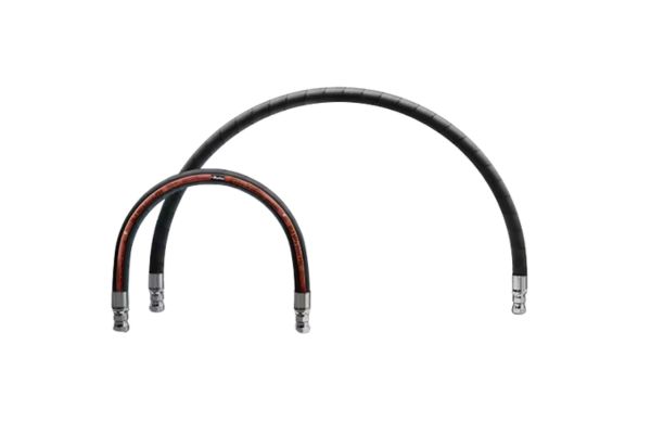
Bend Radius (Minimum) is the smallest radius a hose can be bent to without causing damage. It is always measured to the inside curvature of the hose. Violating the minimum bend radius is a common cause of premature hose failure. When a hose is bent too sharply, its reinforcement wires on the outside of the bend are stretched beyond their elastic limit, while the wires on the inside are compressed and can separate from the inner tube. This creates a weak point, restricts fluid flow, and can cause the hose to kink, permanently damaging it. Generally, hoses with more reinforcement layers or higher pressure ratings have a larger (less flexible) minimum bend radius. Datasheets will always specify this value, which must be respected during routing and installation.
Braid refers to a type of reinforcement construction where wires or textile yarns are interwoven in a crisscross pattern around the inner tube. It is the most common type of reinforcement for low-to-medium pressure hydraulic applications. Hoses like SAE 100R1 (one wire braid) and 100R2 (two wire braids) are industry standards. Braid construction generally offers excellent flexibility compared to spiral-wrapped hoses.
Burst Pressure is the pressure at which a new hose assembly is designed to fail or rupture. It is a critical data point determined by destructive testing in a lab. It is crucial to understand that Burst Pressure is NOT the working pressure. Instead, it is used to calculate the hose’s safety margin. The industry standard for dynamic hydraulic systems is a 4:1 safety factor. This means the stated Maximum Working Pressure is only 25% of the minimum burst pressure. This safety margin accounts for pressure spikes, minor fatigue, and other real-world variables.
| Concept | Definition | Practical Implication |
| Bend Radius | The tightest turn a hose can make without damage. | Respecting this value prevents kinking and premature failure. |
| Braid Reinforcement | Interwoven wire or textile reinforcement layers. | Offers good flexibility for low to medium pressures. |
| Burst Pressure | The pressure at which a new hose is designed to rupture. | Used to determine the safety factor (typically 4:1). Not for operational use. |
Compatibility to Cover?
A hydraulic hose swells and becomes mushy, eventually leaking. The wrong fluid was used, chemically attacking the inner tube and causing the entire hose assembly to fail from the inside out.
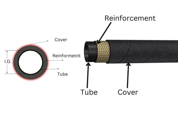
Compatibility refers to the ability of the hose’s inner tube to resist chemical attack from the fluid it carries. The cover is the hose’s outer layer, designed_ to protect the reinforcement from the external environment.

Analyzing Hose Construction and Materials
Compatibility (Chemical) is the ability of the hose’s materials to coexist with the fluid being conveyed without degradation. The most critical component for compatibility is the hose’s inner tube. If the tube material is not compatible with the hydraulic fluid, the fluid will act as a solvent, causing the tube to swell, harden, crack, or delaminate. This breakdown not only leads to leaks but can also send small particles of rubber into the hydraulic system, clogging filters and damaging sensitive components like pumps and valves. Manufacturers provide detailed compatibility charts that cross-reference tube materials with various fluids, from standard petroleum oils to synthetic esters and water-glycol solutions. Checking this chart before selecting a hose is a fundamental step.
Coupling (or Fitting) is the metallic component attached to the end of a hose, allowing it to connect to a port or another assembly. Couplings must be specifically designed for the hose they are being attached to, creating a “matched system” to ensure a reliable, leak-proof connection that can withstand the full working pressure.
Cover is the hose’s outermost layer. Its primary job is to protect the reinforcement layers from the external environment. The cover is formulated to resist abrasion, ozone, UV radiation, chemicals, oil, and sometimes even flames (for applications requiring MSHA approval). The cover provides no pressure-holding capability; its role is purely protective.
| Inner Tube Material | Good Compatibility With | Poor Compatibility With |
| Nitrile (NBR) | Petroleum-based oils, Air | Water-glycol fluids, Phosphate esters |
| Neoprene (CR) | Petroleum oils, some Refrigerants | Phosphate esters, Ketones |
| EPDM | Water-based fluids, Phosphate esters, Steam | Petroleum-based oils, Solvents |
Crimp to Cycle Life?
A brand new hose assembly blows off its fitting at half the rated pressure. The connection was crimped incorrectly, creating a weak point that could not withstand the system’s forces, causing a dangerous failure.
Crimping is the process of mechanically attaching a fitting by deforming a metal collar (ferrule). Cycle life is the number of pressure impulse cycles a hose can withstand before showing signs of fatigue failure.
Manufacturing Reliability and Durability
Crimping is the most common method for attaching fittings to hydraulic hoses. The process uses a machine called a crimper, which contains a set of dies. The hose, with the fitting’s stem inserted and a metal collar called a ferrule placed over it, is placed into the crimper. The machine then uses hydraulic force to close the dies, which compress the ferrule down to a precise, predetermined final dimension. This “crimp diameter” is the single most critical parameter for a successful assembly. If the crimp is too loose, the fitting can blow off under pressure. If it is too tight, it can damage the inner tube and reinforcement, creating a weak point. Every manufacturer provides strict crimp specifications for their specific hose and fitting combinations. Adhering to these specifications is essential for creating a safe and reliable hose assembly.
Cure Date is the date the hose was manufactured, or more specifically, vulcanized (cured with heat and pressure). This date, often printed on the layline, is important for managing stock and determining the hose’s “shelf life.” Rubber compounds can age over time, so using a hose that is many years past its cure date may not be advisable, even if it looks new.
Cycle Life is a measure of a hose’s durability and resistance to fatigue. In the lab, a hose is connected to a test rig that subjects it to repeated pressure impulses, rapidly cycling from zero to its maximum working pressure. The number of cycles it endures before failing is its cycle life. This test simulates the dynamic loads experienced in real-world applications. Standards like ISO 18752 classify hoses based on their cycle performance, with ratings from 100,000 cycles for standard-duty hoses to over 1,000,000 cycles for premium, long-life hoses. A higher cycle life rating indicates a more robust hose designed for severe, high-frequency applications.
Dash Size to Durometer?
The wrong size hose was ordered, causing significant project delays. The nominal size description was misunderstood, resulting in a hose that simply does not fit the existing couplings and ports on the machinery.
Dash size is a standard numbering system that denotes the hose’s inner diameter (ID) in sixteenths of an inch. Durometer is a measurement of the hardness of the rubber or plastic materials used in the hose.
Quantifying Physical Properties
Dash Size is the universal industry shorthand for specifying a hose or fitting’s inner diameter (ID). The system is simple: the number after the dash represents the ID in sixteenths of an inch. For example, a -4 (“dash four”) hose has an ID of 4/16″, or 1/4″. A -8 hose has an ID of 8/16″, or 1/2″. This standardized system eliminates confusion and ensures that a -8 hose from one manufacturer will match a -8 fitting from another. Correctly identifying the dash size is the first step in selecting the right hose, as it determines the volume of fluid the hose can carry.
Delamination describes a type of hose failure where the layers separate from one another. This can occur between the inner tube and the first reinforcement layer, between reinforcement layers, or between the reinforcement and the cover. It is often caused by poor manufacturing quality or using a fluid that is chemically incompatible with the inner tube, causing it to break down.
DIN (Deutsches Institut für Normung) is the German Institute for Standardization. Many hydraulic components, particularly metric fittings like the popular DIN bite-type connectors, are manufactured according to DIN standards.
Durometer is the standard measure of a polymer’s hardness. The test uses a device to press a standardized tip into the material and measures the depth of indentation. For flexible materials like hose rubber, the Shore A scale is used. A higher durometer number indicates a harder material. For example, a typical hose cover may have a durometer of 80A. Hardness is often related to other properties; a harder cover material generally offers better abrasion resistance but may be less flexible.
| Dash Size | Inner Diameter (Inches) | Inner Diameter (mm) |
| -4 | 1/4″ | 6.3 |
| -6 | 3/8″ | 9.5 |
| -8 | 1/2″ | 12.7 |
| -10 | 5/8″ | 15.9 |
| -12 | 3/4″ | 19.0 |
| -16 | 1″ | 25.4 |
Elastomer to Layline?
A hose fails in the field, but there is no way to identify its specifications. All the markings have worn off, making it impossible to order a correct replacement part quickly and safely.
An elastomer is a polymer with rubber-like elasticity, the general term for hose materials. The layline is the continuous text printed on a hose that provides all its critical identification information.

Materials Science and Critical Identification
Elastomer is the technical term for a polymer that displays viscosity and elasticity, commonly known as rubber. Nearly all hydraulic hoses utilize synthetic elastomers for the inner tube and outer cover. The specific type of elastomer is chosen based on the hose’s intended application. Common examples include Nitrile (NBR), Neoprene (Chloroprene or CR), and EPDM, each offering a different profile of chemical, temperature, and environmental resistance.
EN (European Norm) is a standard specification adopted by European countries. Similar to ISO and DIN standards, many hydraulic hoses are manufactured to meet EN specifications, such as EN 853 and EN 857, which are harmonized with the popular SAE 100R1 and 100R2 standards.
Ferrule is the engineered metal collar or sleeve that is part of a hose fitting assembly. During crimping, it is the ferrule that is deformed by the crimper dies to secure the fitting onto the hose, creating a permanent, leak-proof connection.
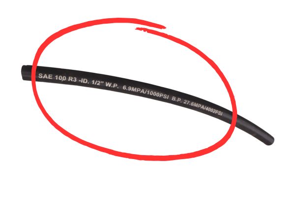
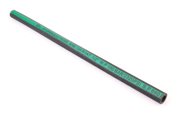
Layline is the single most important source of information on a hydraulic hose. It is the continuous line of text branded or printed along the exterior of the hose. The layline acts as the hose’s specification sheet, providing all the data needed to identify and replace it correctly. A typical layline contains the manufacturer’s name, the hose standard it was built to, the dash size and inner diameter, the maximum working pressure, and often a date code or lot number for traceability. Being able to read and understand the layline is an essential skill for anyone working with hydraulic hoses.
Conclusion
This A-L glossary provides a solid foundation. Understanding these terms is the first step toward building safer, more reliable, and more efficient hydraulic systems for any application.


