Your system is down because a critical connection failed. Choosing the wrong quick coupling type can lead to dangerous leaks, catastrophic pressure loss, and costly contamination of your hydraulic fluid.
The primary quick coupling connection types are poppet valve, flat-face, screw-to-connect, and ball-lock. Each is engineered with a distinct valve and locking mechanism to suit specific applications, from general-purpose pneumatics to extreme-pressure hydraulics, ensuring safety and efficiency.
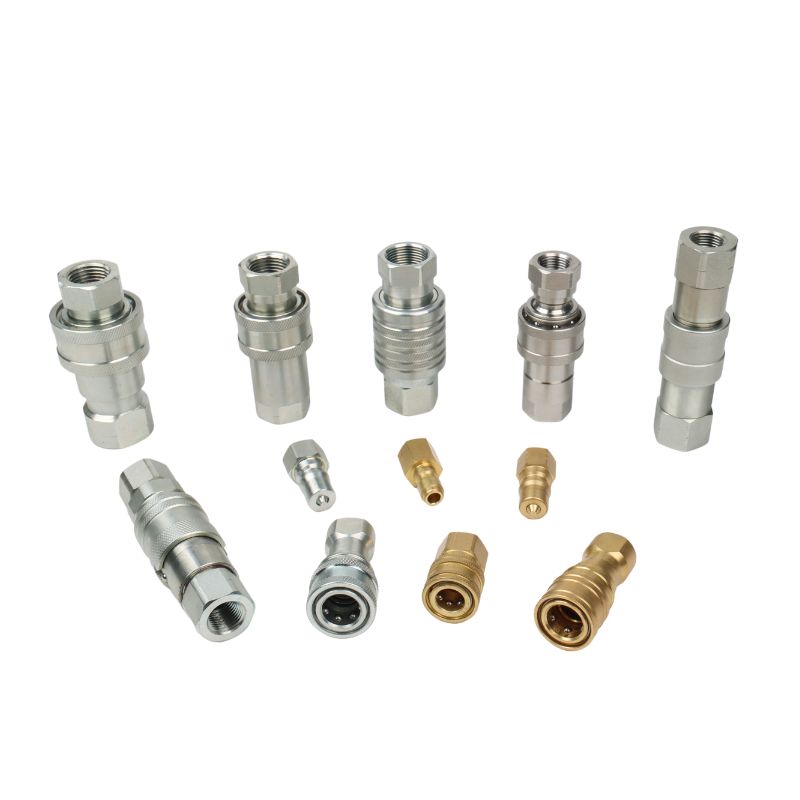
At its core, a quick coupling is a sophisticated valve system designed for rapid connection and disconnection of fluid lines without the use of tools. However, the internal design of this valve system is what truly defines its performance characteristics and suitability for a given task. Selecting the appropriate type is one of the most critical decisions in hydraulic and pneumatic system design. The choice impacts system pressure rating, the degree of fluid spillage upon disconnection, the amount of air included upon connection, and the coupling’s ability to withstand vibration and pressure impulses.
When Should You Use a General-Purpose Poppet Valve Coupling?
You need a reliable, cost-effective coupling for a standard hydraulic or pneumatic application. However, you’re concerned that a basic model might leak during connection or introduce contaminants into your system.
Poppet valve couplings are the go-to choice for general-purpose applications where minor fluid spillage and air inclusion are acceptable. Standardized under ISO 7241-A and -B, they offer a proven, economical solution for connecting agricultural, industrial, and mobile equipment.
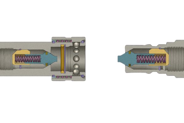
The poppet valve is arguably the most traditional and widely recognized style of hydraulic quick coupling. Its ubiquity is due to a simple, robust design that has been refined over decades. At our manufacturing facilities, we produce vast quantities of these couplings, particularly the ISO 7241-A series, for a global client base in agriculture and industry. While they are not suitable for applications demanding zero leakage, their performance is more than adequate for a huge range of tasks. Understanding the difference between the main poppet standards is key to ensuring interchangeability and proper function within your existing fleet of equipment.
Understanding the Poppet Mechanism and Standards
The poppet valve mechanism is elegantly simple. Inside both the male (nipple) and female (coupler) halves, a conical valve, or “poppet,” is held against a seat by a spring. This keeps both halves sealed when disconnected. During connection, the male nipple pushes against the female poppet, and the nose of the coupler pushes against the male poppet. This unseats both valves simultaneously, creating a flow path through the now-connected coupling. The process is reversed upon disconnection, with the springs snapping the poppets shut.
This action, however, creates a small chamber between the two poppets before they are fully seated or unseated. This chamber traps a small amount of fluid that is spilled upon disconnection and allows a small bubble of air to be ingested upon connection.
Key Poppet Standards:
- ISO 7241-A: This is the most popular standard globally for agricultural and general industrial applications. It features a sleeve that must be manually retracted to connect or disconnect. Its robust, straightforward design makes it a workhorse in the field.
- ISO 7241-B: Commonly found in industrial, chemical, and mold-cooling applications, this standard typically features a push-to-connect design where the sleeve does not need to be retracted for connection. It offers excellent flow characteristics but is not interchangeable with the ISO-A series.
| Feature | ISO 7241-A Series (Ag/Industrial) | ISO 7241-B Series (Industrial) |
| Connection Method | Manual sleeve retraction required | Push-to-connect (typically) |
| Primary Seal | Poppet valve (metal or plastic) | Poppet valve (metal or elastomer) |
| Primary Materials | Carbon Steel, Stainless Steel | Carbon Steel, Stainless Steel, Brass |
| Common Application | Agriculture, mobile equipment, general industry | In-plant hydraulics, mold cooling, chemical transfer |
| Interchangeability | Interchangeable among manufacturers adhering to ISO-A | Interchangeable among manufacturers adhering to ISO-B |
| Key Advantage | Extremely robust, cost-effective, widely available | High flow rates, convenient connection |
Why Are Flat-Face Couplings Essential for Preventing Spillage?
Your application operates in an environmentally sensitive area, or your hydraulic system is highly intolerant of contamination. A standard poppet coupling’s spillage and air inclusion are unacceptable risks.
Flat-face couplings, standardized under ISO 16028, are engineered for near-zero spillage during disconnection and minimal air inclusion during connection. Their flush design makes them the superior choice for preventing hydraulic leaks and system contamination.
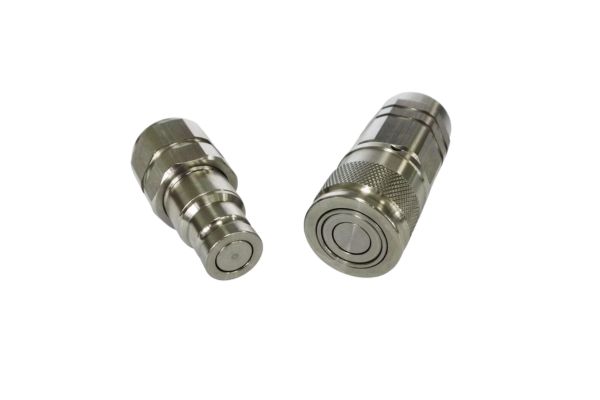
The development of the flat-face coupling was a direct response to the inherent shortcomings of the poppet design. In industries like construction, where hydraulic attachments on equipment like skid steers are changed frequently, minimizing fluid loss and preventing dirt from entering the system is paramount. A single grain of sand introduced by a messy coupling can destroy a multi-thousand-dollar hydraulic pump. The flat-face design eliminates the cavity found in poppet couplings, providing a surface that is easy to wipe clean before connection and ensuring only a thin film of oil is lost upon disconnection. This makes it the undisputed standard for modern, high-performance mobile hydraulics.
The Superior Design and Safety of Flat-Face Couplings
The genius of the flat-face coupling lies in its valve design. Both the male and female halves have flat valve faces that are flush with the end of the coupling when disconnected. During connection, these two flat faces meet first, creating an initial seal. As the connection is completed (usually by pushing the male into the female until a locking sleeve engages), internal mechanisms retract both flat valves away from the faces, opening a clear, high-flow path.
This “seal-before-flow” design provides several critical advantages:
- Near-Zero Spillage: Because the valves are sealed against each other before they open, only the microscopic film of oil between the faces is lost—often less than 0.02 mL.
- Minimal Air Inclusion: The reverse is true on connection. The air gap between the two faces is virtually eliminated before the valves open, preventing the ingestion of performance-robbing air bubbles.
- Easy to Clean: The flush external surfaces have no cavities to trap dirt, dust, or water. A simple wipe with a cloth ensures a clean connection every time.
- Safety Features: Most high-quality flat-face couplings include a locking sleeve that prevents accidental disconnection, which is a critical safety feature in high-pressure systems.
| Feature | Poppet Valve Couplings | Flat-Face Couplings (ISO 16028) |
| Spillage Rating | Low to Moderate | Near-Zero / Excellent |
| Air Inclusion | Low to Moderate | Minimal / Excellent |
| Ease of Cleaning | Difficult (internal cavity) | Excellent (flush external face) |
| Pressure Rating | Good to Very Good | Excellent |
| Contamination Risk | Higher risk of introducing dirt | Low risk due to cleanable surface |
| Common Use | General Agriculture, older Industrial | Construction, modern Hydraulics, sensitive environments |
How Do Screw-to-Connect Couplings Handle Extreme Punishments?
Your application involves extreme high pressure, intense vibration, or severe pressure impulses, such as those from a hydraulic hammer. A standard push-to-connect coupling would quickly fail or disconnect under these conditions.
Screw-to-connect couplings utilize a heavy-duty threaded sleeve to mechanically join and lock the two halves. This design provides unparalleled structural integrity, making them the only choice for ultra-high pressures, heavy vibration, and high-impulse applications.
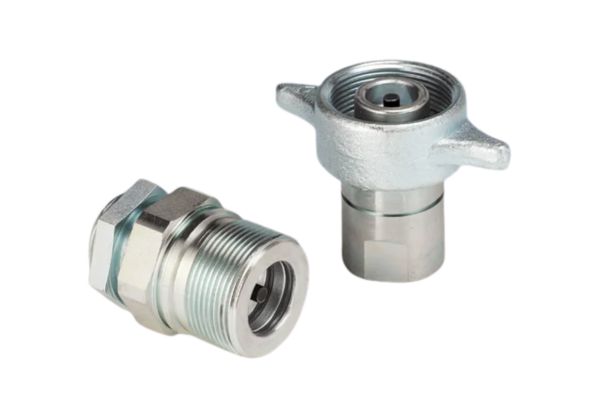
These couplings are the heavyweights of the hydraulic world. They are not designed for speed of connection but for absolute security and strength. Standard push-connect couplings rely on a series of small locking balls. Under intense pressure spikes, these balls can hammer against their retaining groove, a process called “brinelling,” which eventually deforms the metal and leads to failure. The threaded sleeve of a screw-to-connect coupling distributes the load over a vast surface area, making it virtually immune to this type of damage. This is why you will find them on the most demanding equipment on earth, from deep-sea robotics to the massive shears used in demolition.
Mechanism and Advanced Capabilities
The connection principle of a screw-to-connect coupling is based on pure mechanical advantage. The female coupler has a thick, rotatable sleeve with internal threads. The male nipple has a matching set of external threads. To connect, the two halves are pushed together, and the sleeve is manually rotated. This threaded action draws the two halves together with immense force, seating the internal valves and creating an incredibly strong, rigid connection.
This robust design offers unique capabilities:
- Ultra-High Pressure Rating: They are commonly rated for pressures of 10,000 PSI (700 bar) and beyond.
- Resistance to Brinelling: The threaded load distribution prevents damage from the intense, repetitive pressure spikes common in applications like hydraulic breakers.
- Vibration Immunity: The threaded connection effectively preloads the entire assembly, eliminating the micromovements that can cause other couplings to chatter and wear out under heavy vibration.
- Connect Under Pressure: Some advanced designs (conforming to standards like ISO 14540) are specifically engineered to be connected against trapped static pressure. They incorporate a special valve design that allows the trapped pressure to be safely vented during the threading process, a feature that is impossible with most push-to-connect designs.
These couplings represent the ultimate in connection security, swapping speed and convenience for unmatched strength and reliability.
What Makes a Ball-Lock Coupling the Standard for Pneumatics?
You need a fast, simple, and economical way to connect air tools, blowguns, and other pneumatic equipment. The demands are for speed and one-handed operation, not high-pressure hydraulic sealing.
Ball-lock couplings, often called industrial interchange or pneumatic couplings, use a simple ball-bearing mechanism to provide rapid, one-handed connection. Their low cost and ease of use have made them the universal standard for compressed air systems and low-pressure fluid lines.
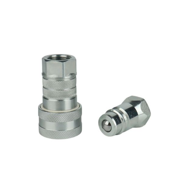
The ball-lock coupling is perhaps the most common quick connect in any workshop or factory. Its design prioritizes speed above all else. A single hand can retract the sleeve, insert the nipple, and release the sleeve to lock it in place. While the term “ball-lock” describes the mechanism, it’s crucial to understand that there are numerous “interchange” profiles on the market (Industrial, ARO, Tru-Flate, etc.). These profiles refer to the specific dimensions of the male nipple and are not interchangeable with one another. Using a Tru-Flate nipple with an Industrial coupler, for example, will not create a secure connection. At Topa, we manufacture all the major interchange profiles to ensure our customers can match the specific standard used in their facility.
Interchange Profiles and Valving Options
The ball-lock mechanism is straightforward: The female coupler contains a set of locking balls held in place by a spring-loaded outer sleeve. When the sleeve is retracted, the balls can move outward, allowing the grooved male nipple to be inserted. Releasing the sleeve forces it over the balls, locking them into the nipple’s groove.
Key Industrial Interchange Profiles:
It is essential to match the profile of the nipple to the coupler.
- Industrial Interchange (MIL-C-4109): The most common profile in North America.
- ARO Style (ARO 210): Another popular profile with a different nipple nose shape.
- Tru-Flate Style (Automotive): Common in the automotive service industry.
- European High-Flow: A standard common in Europe designed for maximum airflow.
Valving Options:
Unlike hydraulic couplings where both halves are almost always valved, pneumatic couplings offer more options.
- Valved Coupler, Valved Nipple: Used when both the tool and the air line need to seal when disconnected.
- Valved Coupler, Unvalved Nipple: The most common configuration. The coupler on the air hose seals when disconnected, but the nipple on the tool is a simple, unvalved (straight-through) connector. This is ideal for tools like blowguns where backpressure is not a concern.
- Unvalved Coupler, Unvalved Nipple: A straight-through connection with no valves on either side. Used for applications where flow must not be restricted and sealing upon disconnection is not needed, such as in some fluid transfer lines.
| Feature Summary | Poppet | Flat-Face | Screw-to-Connect | Ball-Lock (Pneumatic) |
| Primary Use | General Hydraulics | High-Spec Hydraulics | Extreme Pressure/Vibration | Pneumatics, Low-Pressure Fluid |
| Spillage | Moderate | Near-Zero | Varies (often low) | High (if valved) |
| Pressure Rating | Up to 5000 PSI | Up to 6000 PSI | Up to 10,000+ PSI | Up to 300 PSI |
| Key Advantage | Cost-Effective | Cleanliness & Safety | Strength & Security | Speed & Convenience |
| Connection Method | Push or Sleeve Retract | Push-to-Connect | Threaded Sleeve | One-Handed Push |
Conclusion
Selecting the right quick coupling type by matching its design to the application’s pressure, spillage, and environmental demands is fundamental for creating a safe, efficient, and reliable fluid power system. If you want to choose the most suitable quick couplings for your hydraulic system, contact us now and Topa can help you!


