Hydraulic hoses are the veins of an excavator’s power system—every movement of the boom, arm, and bucket depends on their strength and precision. Building a hose assembly that performs like an OEM part isn’t about shortcuts; it’s about discipline in every step—from selecting the right components and preparing the hose, to precise crimping and careful installation.
The Foundation: Selecting the Right Components
The integrity of a hose assembly is determined before the crimper is even switched on. The selection of correct, compatible components is the foundation of a safe and reliable crimp. Using mismatched parts is a direct path to failure.
Matching Hose to Application
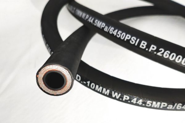
Start with the hose that was designed for the job. Verify that its pressure rating, temperature range, and fluid compatibility meet the excavator’s system requirements. Using an under-rated hose guarantees a premature and often catastrophic failure.
The “Matched System” Rule
This is the most critical rule in hose assembly: hose and fittings must come from the same manufacturer and be part of a “matched system.” Each manufacturer engineers their hose tolerances and fitting dimensions to work together perfectly. Mixing brands is a dangerous gamble.
Choosing the Correct Die Set
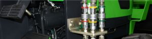
Every crimper uses interchangeable die sets to accommodate different hose and fitting sizes. Using the wrong die set is a common and critical error. Always consult the crimper manufacturer’s specific crimp chart to select the correct die set for your hose and fitting combination.
Precision in Preparation: The Measure and Cut
Precision is not optional — it’s the foundation of a reliable hose assembly. The accuracy of your measurement and cut determines how well the hose fits, seals, and performs under pressure. Even a few millimeters of error can lead to stress points, misalignment, or premature leaks.
Measuring for Success
When replacing an existing hose:
- Measure from sealing surface to sealing surface to determine the Overall Length (OAL).
- For a new assembly, calculate the Cut Length using this formula:
Cut Length = OAL – (Cut-Off Factor A + Cut-Off Factor B)
Each fitting has a specific cut-off factor—the distance from the fitting’s sealing face to the end of the hose. Always refer to the manufacturer’s catalog for these values.
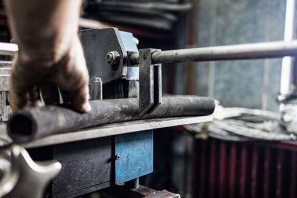
The Importance of a Clean, Square Cut
A precise 90° cut ensures the hose seats evenly inside the fitting shell.
- Use only a professional hose saw with an abrasive blade.
- Avoid hacksaws or chop saws that can fray the wire braid or leave uneven ends.
- A slanted cut prevents the hose from bottoming out squarely, leading to poor crimp quality and possible leaks.
| Tool Type | Cut Quality | Effect on Hose |
| Abrasive Hose Saw | Perfectly square, smooth | Maintains hose structure |
| Hacksaw | Uneven, frayed | Damages reinforcement |
| Chop Saw | Risk of heat damage | Can harden cover |
Skiving vs. No-Skive: Know Your Hose
Not all hoses are prepared the same way before crimping. Knowing whether your hose requires skiving prevents assembly failure.
| Feature | Skive Hose | No-Skive Hose |
| Preparation | Outer (and sometimes inner) cover removed | No cover removal needed |
| Typical Use | Older or very high-pressure hoses | Modern hoses with improved bonding |
| Tools Required | Skiving machine or knife | None |
| Risk if Done Incorrectly | Poor adhesion or blow-off | Damages reinforcement and causes failure |
| Identification | Specified in catalog or on hose label | Marked as “No-Skive” or “NS” |
Tip: Never skive a no-skive hose — doing so compromises the integrity of the reinforcement layer and leads to catastrophic failure.
Critical Alignment: Hose and Fitting Insertion
In hydraulic assembly, alignment is everything. Even the most accurate cut and the strongest crimp mean nothing if the hose isn’t fully and correctly inserted into the fitting shell. This step determines whether the crimping force is distributed exactly where the fitting was designed to hold — at the reinforcement layer of the hose. A misaligned or under-inserted hose creates weak points that lead to leaks, blow-offs, or fitting separation under pressure.
Marking the Insertion Depth
Every hose-fittings combination has a specified insertion depth — the distance the hose must enter the fitting to reach its designed grip zone. This information is listed in the manufacturer’s catalog or technical manual.
To prepare:
- Measure the insertion depth accurately from the end of the hose.
- Mark this distance with a silver marker or white chalk line — bright enough to remain visible during insertion.
- Double-check the mark’s position; even a few millimeters off can cause incomplete engagement inside the shell.
This simple mark becomes your visual assurance that the hose is seated correctly before crimping.
The Technique of Proper Insertion
With the hose cut and marked, it’s time to seat it into the fitting:
- Push the hose straight into the fitting with firm, continuous pressure.
- Avoid twisting — rotation during insertion can damage the reinforcement or misalign the internal wire pattern.
- Use light lubrication only with clean hydraulic fluid. Never use grease, oil, or silicone-based lubricants, as they can interfere with crimp grip and lead to slippage.
- Continue inserting until the end of the fitting shell aligns exactly with your silver mark.
Tip: If you feel abnormal resistance halfway through, stop and inspect for frayed wires, debris, or an incorrect fitting type.
Pre-Crimp Visual Confirmation
Before operating the crimper, take a moment to verify alignment. This inspection step is quick but critical — it confirms that all your preparation work has achieved the correct positioning.
Perform these checks:
| Inspection Point | Correct Condition | Common Error | Result |
| Mark visibility | Mark is visible and flush with the back of the shell | Mark fully covered | Hose over-inserted; may crush liner |
| Shell alignment | Hose end meets fitting shoulder evenly | Gap visible | Hose under-inserted; weak crimp |
| Twist check | Mark line runs straight | Spiral or distorted mark | Twisted hose; stress under pressure |
| Surface condition | Clean, dry, no oil or debris | Grease or dust present | Compromised grip during crimp |
A proper pre-crimp visual check saves hours of rework and prevents dangerous failure in the field.
The Moment of Truth: The Crimping Process
This is where the components are permanently joined into a single, high-integrity unit. The crimper applies immense, controlled force to deform the fitting shell, creating a mechanical and hydraulic seal that will last the life of the hose.
Setting the Crimp Diameter
Using the manufacturer’s crimp chart, find the correct final crimp diameter for your hose and fitting combination. Adjust the micrometer or digital setting on your crimper to this exact specification. This is the single most important setting on the machine.
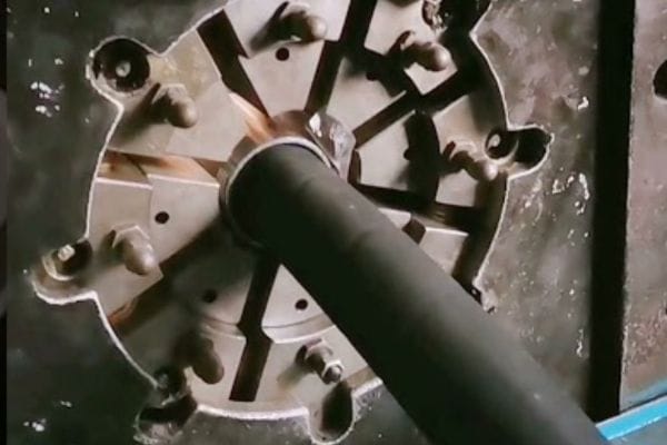
Positioning the Assembly in the Crimper
Place the assembly into the crimper, ensuring the fitting is resting on top of the dies. Position it so the crimp will occur on the main body of the fitting shell, not on the “bubble” or threaded area.
Executing the Crimp Cycle
Following your machine’s safety procedures, activate the crimper. The machine will push the dies together until the preset diameter is reached, then stop or retract. Keep hands and clothing clear of the machine during the entire cycle.
Verification and Finalization: The Quality Control Step
A crimp is not complete until it has been verified. This final quality control check provides objective proof that the assembly is safe and has been manufactured to the correct specification. Do not skip this step.
The Post-Crimp Diameter Check
Using a set of calipers, measure the diameter of the crimped shell at several points (middle and ends) and in several orientations. The measured average diameter must be within the manufacturer’s specified tolerance (e.g., +/- .005 inches) of your target crimp diameter.
Visual Inspection of the Crimp
Visually inspect the finished crimp. It should be uniform and straight. Look for excessive die marks, a crooked or angled appearance, or any signs that the fitting is not concentric with the hose. These are signs of a bad crimp that must be scrapped.

Cleaning, Capping, and Labeling
After a successful inspection, thoroughly clean the assembly with a cleaning projectile or solvent to remove cutting debris. Immediately cap both ends to prevent contamination. Labeling the assembly with its build date is a best practice for tracking service life.
| Crimp Defect | Visual Cue | Root Cause(s) | Solution |
| Over-Crimp | Crimp diameter is smaller than specification. The shell may look crushed or distorted. | Crimp setting was too small. Wrong die set was used. | Discard the assembly. Verify the crimp specification and die set number from the manufacturer’s chart and re-make the hose. |
| Under-Crimp | Crimp diameter is larger than specification. The fitting may feel loose. | Crimp setting was too large. Wrong die set was used. Crimper was not fully cycled. | Discard the assembly. Verify the crimp specification, die set number, and machine operation. Re-make the hose. |
| Crooked Crimp | The fitting is visibly angled relative to the hose. | The hose was not cut squarely. The assembly was not held straight in the crimper during the crimp cycle. | Discard the assembly. Use a proper hose saw to ensure a 90° cut. Carefully position the assembly in the dies. |
| Burnt Appearance | Scorched or melted look on the crimp shell or hose cover. | Misaligned dies or extreme pressure from a gross over-crimp can generate massive frictional heat. | This indicates a severe dimensional problem. Discard immediately and investigate the die and crimp setting selection. |
| Leaking at Crimp | Fluid weeping from the junction of the hose and fitting shell under pressure. | Usually caused by an under-crimp, a skived no-skive hose, or using an incorrect hose/fitting combination. | De-pressurize immediately. Discard the assembly and meticulously review every step of the selection and assembly process. |
Installation on the Excavator: Achieving a Perfect Fit
A perfectly built hose means nothing until it’s installed correctly. Improper routing, twisting, or over-tightening can destroy even a factory-grade assembly within days. Correct installation is what transforms a well-made hose into a long-lasting, high-performance hydraulic line.
Step 1 – Identify the Correct Routing Path
Before connecting anything, review the excavator’s hydraulic schematic or service manual. Each hose is designed for a specific circuit, whether it’s boom lift, arm curl, bucket tilt, or swing function.
- Trace the original routing before removal or take reference photos.
- Ensure no contact points with sharp edges, moving parts, or hot components like exhaust manifolds.
- Avoid tight bends — maintain at least the hose’s minimum bend radius (usually 6–8 × hose OD).
- Where hoses move with the boom or stick, leave enough slack for full articulation without tension.
| Common Error | Consequence | Correct Practice |
| Hose stretched at full extension | Early fitting separation | Add slack and re-clamp |
| Hose rubbing metal edge | Abrasion, hose burst | Install protective sleeve |
| Hose twisted during routing | Internal wire fatigue | Follow natural hose lay |
Step 2 – Prepare the Port Connections
Each hydraulic port has its own sealing style — JIC 37°, ORFS, BSPP, or Metric 24°. Inspect every port and adapter before connection.
- Clean all threads and sealing surfaces using lint-free cloths.
- Replace O-rings or backup washers if worn, cracked, or flattened.
- Confirm thread compatibility — never force mismatched threads.
- Apply only approved thread sealant (e.g., Loctite 545 for NPT); do not use Teflon tape, which can shed into the system.
Tip: Always install fittings by hand until finger-tight, then torque to specification with a calibrated wrench. Over-tightening distorts the sealing surface and causes leaks.
Step 3 – Mount the Hose Assembly
- Align the hose naturally with the fitting port; never twist to make it reach.
- Hand-thread first to prevent cross-threading.
- Torque according to manufacturer’s chart (e.g., 9/16-18 JIC = 18–22 ft-lb).
- Support long runs with factory clamps spaced every 18–24 in (450–600 mm).
- Ensure the mark on the hose (used for insertion check) is still visible — confirming the hose has not slipped during installation.
Step 4 – Secure, Protect, and Test
After the hoses are installed:
- Clamp all hoses firmly using rubber-lined clamps; never crush or flatten.
- Add abrasion sleeves or spiral guards at contact areas.
- Bundle hoses that move together using Velcro straps, allowing controlled motion.
- Pressure-test the system: run at low idle first, watching for leaks or twisting.
- Once verified, cycle each function to full extension several times and re-check clamps and fittings.
Safety Reminder: Never check for leaks with bare hands. Use cardboard or paper — escaping hydraulic oil under pressure can penetrate skin.
Step 5 – Final Inspection and Documentation
After successful installation and testing:
- Wipe the hoses clean to spot any new leaks during later checks.
- Re-torque critical connections after the first 10 hours of operation.
- Record hose details (part number, crimp ID, installation date) on the machine’s service log or tag.
- Schedule periodic inspection every 250–500 hours depending on duty cycle.
A flawless hydraulic hose assembly doesn’t happen by chance; it’s the result of precision, consistency, and adherence to proven standards. When each stage—selection, preparation, crimping, and installation—is executed correctly, the result is an excavator hose that performs reliably under the harshest conditions.
FAQ
Can I re-crimp a fitting that is under-crimped or leaking?
No, never. The metal of the fitting shell is work-hardened during the initial crimp. Attempting to crimp it a second time will result in an unpredictable and unsafe connection that is prone to cracking and failure. The assembly must be cut apart and discarded.
What happens if I use a fitting from Brand A and a hose from Brand B?
Even if they look similar, the manufacturing tolerances for the hose’s outer diameter and the fitting’s shell are designed to work as a matched pair. Mixing brands can lead to an under-crimp (blow-off risk) or an over-crimp (damaging the hose tube), both resulting in failure.
My crimp diameter is correct, but the fitting still blew off. Why?
The most likely cause is that the hose was not fully inserted into the fitting before crimping. If the hose isn’t pushed all the way to the bottom, the “teeth” inside the fitting shell cannot get a sufficient bite into the hose’s wire reinforcement. Always use an insertion depth mark.
How often should I calibrate my hydraulic crimper?
Calibration should be checked regularly, typically on an annual basis at a minimum, or any time you suspect your crimp diameters are not matching your settings. Use a certified gauge and follow the manufacturer’s calibration procedure.
Is it necessary to clean the inside of the hose after cutting?
Yes, it is absolutely essential. The abrasive cutting process generates fine particles of rubber and metal that are forced into the hose. If not cleaned out (typically by firing a foam projectile through the line), this debris will be flushed into your excavator’s sensitive pumps and valves, causing extreme damage.
Why does a new hose start leaking soon after installation?
Most early leaks are caused by routing issues, improper torque, or the hose being twisted during installation. Even a perfectly crimped hose will fail if it rubs on metal, is over-tightened, or is forced into an unnatural bend. Re-check routing, clamp spacing, and torque to prevent early failure.