You are operating your heavy agricultural tractor or loader during peak harvesting season when an unexpected hydraulic failure strikes. Suddenly, the front-end loader arms shake violently under load, or the implement lift mechanism sinks mid-operation, stalling your field productivity. You replace the worn piston seals and flush the system, but within weeks, the exact same leakage and sluggish performance return. The hidden culprit is rarely a defective seal material or low-quality fluid. Instead, it is an engineering mismatch: an incorrect port size that restricts flow, spikes fluid velocity, and destroys components from the inside out.
Why Does Port Sizing Matter For Fluid Velocity?
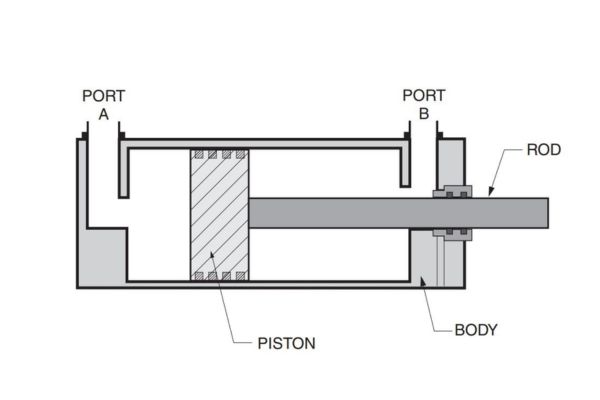
Port sizing dictates the boundary conditions of fluid dynamics within a high-pressure system, directly controlling raw linear velocity. When you force high-volume fluid through an incorrect port size that is smaller than original specifications, the fluid velocity increases exponentially to maintain volumetric flow rate requirements. This hyper-velocity condition alters steady laminar paths into chaotic fluid patterns, subjecting internal components to continuous hydraulic stress.
How Do Over-Restricted Ports Accelerate Volumetric Heat Generation?
Forcing fluid through restricted port channels transforms available mechanical force directly into thermal energy due to extreme fluid friction. As localized oil temperatures spike beyond safe thermal windows, the hydraulic fluid loses its baseline lubricating properties rapidly.
- Excessive heat strips the vital protective oil film away from the moving piston rod surface.
- Accelerated metal-on-metal wear occurs between the internal gland bushes and the cylinder rod.
- High thermal loads cause internal control valve spools to stick or bind during critical cycles.
Can Turbulent Flows Break Down High-Pressure Seal Chains?
High-velocity fluid entering a cylinder through an undersized port generates severe internal turbulence and fluid shearing. This continuous fluid bombardment erodes the micro-sealing lips of high-pressure polyurethane and nitrile seal configurations.
- High fluid turbulence creates local pressure fluctuations that deform standard rod wipers.
- Turbulent back-flows micro-fracture primary sealing rings, initiating bypass paths.
- Internal fluid shearing tears long-chain polymer structures apart, degrading structural seal support.
| Port Configuration | Internal Velocity Profile | Thermal Risk Factor | Volumetric Efficiency Impact |
| Correctly Sized Bore | Stable Laminar Flow | Low (Nominal Balance) | Optimal Component Delivery |
| Over-Restricted Port | Severe Turbulent Shear | Critical Heat Spikes | Drastic Pressure Loss |
How Does Port Mismatch Induce Destructive Pressure Drops?
An incorrect port size acts as an unintentional system restriction, creating severe localized pressure differentials across the entry boundary. This fluid constriction robs your hydraulic system of effective operating power while multiplying the load on your primary hydraulic pump. When pressure drops become excessive, the actuator fails to generate the required linear force, causing critical implements to stall out during heavy-duty lifting maneuvers.
What Happens To Actuator Force When Backpressure Spikes?
When return ports are restricted, fluid cannot evacuate the hydraulic cylinder quickly enough, creating a massive backpressure spike on the opposite side of the piston head. This excessive backpressure acts as an opposing force that directly subtracts from the cylinder’s forward push capacity.
- Net lifting force drops significantly, making the machine feel completely underpowered.
- The hydraulic system consumes double the fuel to move identical physical weights.
- Internal fluid stagnation prevents the cylinder from retracting smoothly, creating erratic movement.
Does Cavitation Occur When Intake Ports Constrict Flow?
When a cylinder extends rapidly while choked by an undersized intake port, the pump demands more fluid than the port can physically supply, creating a localized vacuum pocket. This severe vacuum drop drops fluid pressure below the vapor pressure point, triggering the explosive formation of micro-bubbles.
- Micro-bubbles collapse violently against internal steel walls at pressures exceeding 10,000 PSI.
- Severe bubble implosions micro-pit the internal surface of the honed cylinder tube.
- Continuous cavitation erosion creates microscopic metal debris that scoring internal seal paths.
| Pressure Drop Hazard | Primary Operational Symptom | Internal System Root Cause | Affected Mechanical Area |
| Restrictive Backpressure | Severe Actuator Force Drop | Restricted Return Fluid Path | Piston Head Opposite Face |
| Intake Vacuum Drop | Violent Local Cavitation | Choked Suction Boundary Line | Internal Honed Tube Wall |
Why Do Mismatched Ports Threaten Cylinder Structural Integrity?
Operating industrial machinery with an incorrect port size subjects the entire structural enclosure to severe fatigue from extreme pressure spikes. When fluid flow is bottlenecked, the system experiences massive kinetic energy transfers every time an automated control valve shifts positions. These intense structural pressure spikes cause microscopic structural fatigue that slowly compromises the physical safety parameters of your high-pressure components.
Can Backpressure Build-Up Yield Severe Mechanical Overload?
Continuous operation against restricted fluid ports generates massive pressure multiplications that far exceed the maximum rated capacity of standard industrial steel tubes. This extreme pressure buildup places severe tensile stress on the cylinder walls, leading to irreversible mechanical deformation over time.
- High tensile stresses cause the micro-finished cylinder barrel to balloon out of round.
- Barrel deformation increases the internal clearance gap between the piston head and the tube.
- Oversized gaps allow high-pressure fluid to bypass the piston seals, causing chronic lift loss.
Does Pressure Spiking Fracture Critical Cylinder Welded Mounts?
The violent fluid pressure spikes triggered by restricted port boundaries generate immense shock loads that travel directly into the mechanical attachment joints. These sudden kinetic shocks concentrate heavy stress directly onto the structural ear welds and mounting lugs of the cylinder.
- High-frequency fluid shocks initiate microscopic stress cracks across the mounting weld beads.
- Repetitive shock loading propagates structural cracks deep into the base metal matrix.
- Catastrophic mount failure occurs under load, tearing the cylinder completely off the machine frame.
| Structural Load Risk | Primary Material Failure | High-Stress Focus Point | Long-Term Operational Outcome |
| Internal Tensile Stress | Cylinder Barrel Expansion | Honed Tube Centerline | Chronic Fluid Bypass Leaks |
| Kinetic Fluid Shock | Weld Bead Micro-Cracking | Mounting Lugs and Ears | Sudden Structural Mount Tear |
How Does Incorrect Port Size Degrade System Synchronization?
Precision fluid power applications rely heavily on perfectly balanced fluid distribution across every active actuator branch. Installing a replacement cylinder with an incorrect port size into a multi-cylinder system alters individual branch fluid resistance completely. This unbalance causes uneven fluid distribution, destroying synchronization and causing mechanical binding across connected heavy structural linkages.
Why Do Dual Lift Cylinders Lose Parallel Lift Alignment?
When dual actuators managing a single front-loader arm have mismatched inlet ports, the cylinder with the smaller port experiences higher fluid restriction. Consequently, fluid naturally paths into the less-restricted cylinder first, causing it to extend faster than its paired unit.
- Front-loader buckets raise unevenly, causing materials to spill out the lower side.
- Uneven lift speeds place severe twisting forces across the entire structural boom assembly.
- Connecting cross-shafts experience intense structural torsional stress, leading to alignment failure.
Does Port Restriction Create Lag In Critical Self-Leveling Operations?
Automated self-leveling linkages require instantaneous hydraulic responses to adjust implement tilt angles smoothly during arm extension cycles. A restricted connection port delays vital fluid transfers, causing the self-leveling tracking function to lag behind boom movements.
- Pallet forks tilt forward unexpectedly at high lift heights, creating severe safety risks.
- The operator must make frequent manual corrections, increasing operational fatigue.
- Hydraulic tracking lag triggers sudden pressure surges that damage sensitive valve spools.
| Multi-Cylinder System | Direct Operational Defect | Underlying Hydraulic Mechanism | Structural Consequence |
| Dual Boom Lift Setup | Asymmetric Extension Speeds | Unbalanced Branch Resistance | Severe Torsional Boom Twist |
| Automated Self-Leveling | Tracking Response Lag | Delayed Border Fluid Transfer | Dangerous Implement Angle Drift |
Why Does Wrong Sizing Cause Premature Fluid Breakdown?
The intensive fluid friction and fluid shearing forced by an incorrect port size degrade the chemical stability of your hydraulic oil supply. Fluid power mediums rely on stable chemical properties to maintain precise film thickness under high working pressures. When forced through fluid bottlenecks, the hydraulic fluid breaks down quickly, converting premium oil into a thin, contaminated compound.
Does Excessive Shearing Lower Hydraulic Oil Viscosity?
Forcing high-pressure oil through restricted port geometry subjects fluid molecules to intense mechanical shearing forces. This extreme friction cleaves the long-chain polymer viscosity index improvers that stabilize modern hydraulic fluids.
- The oil thins out prematurely, losing its capacity to support heavy structural loads.
- Thin fluid slips easily past high-pressure dynamic seals, increasing internal leakage.
- Loss of proper viscosity accelerates wear across internal hydraulic pump piston shoes.
How Do Hot Spots Accelerate Piston Seal Degradation?
The restricted passages of mismatched ports generate localized, ultra-high-temperature fluid zones known as hydraulic hot spots. As this overheated fluid circulates through the cylinder assembly, it bakes the primary seal material continually.
- Continuous thermal baking hardens elastic polyurethane compounds, eliminating vital seal flexibility.
- Brittle sealing lips crack open under minimal pressure loads, causing chronic system drift.
- Thermal oxidation triggers varnish formation, which coats the rod surface in abrasive residue.
| Fluid Degradation Phase | Chemical Reaction Mode | Internal Component Trigger | Primary Downstream System Failure |
| Polymeric Fluid Shearing | Viscosity Index Cleavage | Restricted Flow Boundary | Increased Internal Component Leaking |
| Thermal Concentration | Accelerated Oil Oxidation | Localized Port Hot Spots | Seal Hardening and Varnish Deposits |
Can Incorrect Ports Damage External Component Lines?
The destructive fluid dynamics triggered by an incorrect port size extend beyond the hydraulic cylinder shell, directly damaging external supply lines. Fluid bottlenecks generate high-pressure counter-waves that pulse back through connected lines every time system direction changes. These continuous high-pressure pulses subject external lines to intense mechanical and pressure fatigue, causing premature routing failures.
Why Do Supply Hoses Experience Severe Whipping Risks?
Restricted connection ports generate massive pressure pulses that cause flexible external rubber hoses to stiffen and kick violently during operational cycles. This repetitive structural twisting degrades the internal high-tensile steel wire reinforcement layer inside the hose body.
- Supply hoses rub continually against the sharp steel edges of the machinery chassis.
- Outer protective rubber covers wear through, exposing wire braids to environmental rust.
- Weakened reinforcement layers rupture under normal operating pressure, creating severe safety hazards.
Does Port Mismatch Lead To Quick Coupler Seepage Problems?
High-frequency backpressure waves generated by undersized connection boundaries put constant pressure on external quick-disconnect connection fittings. These intense pressure pulses fatigue the internal sealing elements located within the coupler assembly.
- Internal check-valve o-rings experience rapid extrusion wear, causing slow fluid weeping.
- Heavy fluid seepage coats the remote connection valve area in dirt and abrasive farm debris.
- Damaged quick couplers allow air contamination to enter into the main suction oil streams.
| External Line Area | Primary Physical Damage | Dynamic Stress Mechanism | Associated Fleet Risk Factor |
| Flexible Supply Hoses | Wire Braid Rupture Failure | High-Frequency Kick Pulses | Sudden High-Pressure Oil Blowout |
| Quick Disconnect Couplers | Internal O-Ring Extrusion | Continuous Backpressure Surge | Chronic Fluid Seepage and Dust Ingress |
How Do I Triage Port Mismatch In The Field?
Locating a hidden fluid restriction across your machinery fleet does not require advanced workshop diagnostics. You can execute an accurate operational assessment directly in the field using standard diagnostic techniques. By systematically observing operational symptoms and temperature changes, you can verify whether an incorrect port size is choking your system before catastrophic component failures occur.
What Visual Signs Confirm Fluid Restricting Flow Ports?
Identifying port restriction begins with a comprehensive visual assessment of the external line behavior during heavy extension cycles. Pay close attention to how lines react when the system reaches maximum load thresholds.
- Watch for physical hose jump or whipping movements when control valves engage.
- Check the outer surface of the cylinder barrel for localized paint discoloration or blistering.
- Inspect connection fitting threads for signs of micro-stretching or recurring fluid weep paths.
Can Hand-Feel Temperature Tests Locate System Blockages Safely?
You can track down extreme fluid friction zones by carefully monitoring localized heat differences across your hydraulic circuit. Use an infrared thermometer gun or follow safe hand-feel techniques after the machine operates for a brief period.
- Check the exact junction point where the supply hose meets the cylinder entry port.
- Look for sharp temperature jumps between the main delivery line and the port inlet fitting.
- A localized temperature increase of over 15°C across the port boundary confirms an active flow restriction.
| Field Triage Step | Targeted Inspection Focus | Positive Fault Indicator | Confirmed Hydraulic Issue |
| Structural Motion Check | Flexible Supply Hose Assembly | Dynamic Whipping or Kicking | Severe Backpressure Wave Generation |
| Thermal Boundary Scan | Hose-to-Port Fitting Junction | Temperature Differential > 15°C | Severe Localized Fluid Friction |
How To Reverse Engineer Legacy Cylinder Port Configurations?
Sourcing replacement components for older industrial or agricultural machinery requires accurate reverse engineering to avoid connection sizing errors. Many older cylinders lack legible manufacturer part numbers, meaning your team must identify thread sizes manually. Following a structured measurement process ensures your replacement components integrate flawlessly without choking system flow parameters.
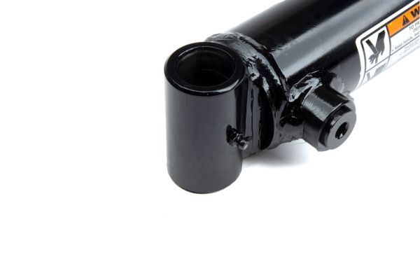
How Do You Decode Unknown Industrial Thread Sizes Precisely?
Accurately decoding unknown fitting threads requires high-precision caliper measurements and professional pitch gauges. Never guess a thread configuration based on visual appearance alone, as different global standards look identical to the naked eye.
- Measure the exact outer diameter of the male port thread using a digital caliper.
- Use a thread pitch gauge to determine the exact number of threads per inch or millimeter spacing.
- Compare your measurements against standardized industrial thread charts to identify the exact connection model.
Can You Match OEM Geometry Configuration Without Engineering Drawings?
When engineering drawings are missing, you can create an accurate installation profile by completing a detailed reverse-engineering worksheet. Document every critical size boundary before ordering custom replacement units.
- Record the exact center-to-center pin distance when the cylinder is fully retracted.
- Verify the precise orientation angle of the ports relative to the main mounting pins.
- Measure the exact clearance envelope around the port boss area to prevent chassis interference.
| Measurement Step | Precision Tool Required | Target Dimensional Data | Downstream Connection Benefit |
| Thread Identification | Digital Caliper & Pitch Gauge | Outer Diameter & Thread Pitch | Eliminates Cross-Threading Damage |
| Geometric Envelope | Reverse-Engineering Matrix | Port Orientation & Mount Center | Guarantees Interference-Free Install |
How To Implement A Reliable Risk Prevention Inspection?
Eliminating connection configuration risks across your machinery fleet requires a structured preventive maintenance and inspection routine. Unscheduled equipment downtime during peak operating seasons causes heavy financial losses. Implementing regular pre-shift inspections and seasonal checks ensures your connection fittings stay secure and fully operational year-round.
What Daily Pre-Shift Check Routines Avoid Port Failures?
Your equipment operators should complete a quick visual inspection of all hydraulic connections before starting daily machinery operations. Catching early warning signs prevents minor fluid leaks from developing into catastrophic component failures out in the field.
- Walk around the machine to check all port connections for new fluid dampness or weeping.
- Verify that all flexible supply hoses can move freely without kinking or binding during execution.
- Ensure all quick-coupler dust caps are clean and securely snapped into position.
How To Plan Seasonal Maintenance Verification Pipelines Securely?
Schedule an intensive hydraulic system audit during low-utilization periods between active seasonal work cycles. This deep-dive verification process checks the mechanical condition of every high-pressure connection across your entire fleet.
- Clean all port connection junctions thoroughly using specialized industrial degreasers.
- Use precision calipers to verify that no connection fittings are showing thread elongation.
- Replace any component connection seals that show signs of hardening or thermal degradation.
| Maintenance Cycle | Target Inspection Pipeline | Technical Action Plan | Strategic Fleet Outcome |
| Daily Pre-Shift Check | External Visual Connection Audit | Identify New Fluid Dampness Trails | Catches Minor Fitting Leaks Early |
| Seasonal System Audit | Deep-Dive Mechanical Evaluation | Verify Thread Profiles and Caliper Sizes | Eliminates Active Fleet Sizing Errors |
Conclusion
By systematically addressing port sizing discrepancies, eliminating fluid restrictions, and verifying thread compatibility, you insulate your hydraulic system from catastrophic failures. This engineering discipline protects your equipment investments, maximizes volumetric efficiency, and eliminates premature component wear across your agricultural or industrial operations. If you discover a port mismatch or require high-precision, zero-defect custom manufacturing for your fleet, it is time to optimize your fluid components. For custom reverse engineering or to upgrade your fleet connections to absolute OEM precision, contact us today to connect with our engineering team.
Frequently Asked Questions
Can I install a cylinder with smaller ports if I use high-flow adapters?
No, using high-flow adapters on an undersized port does not eliminate internal fluid restrictions. While the adapter matches the external hose size, the internal port throat remains a structural bottleneck. This restriction accelerates fluid velocity, spikes system heat, and generates destructive turbulence right at the cylinder boundary.
What is the best way to confirm an unknown port thread type in the field?
The most reliable method is using a digital caliper alongside a thread pitch gauge. Measure the exact outer diameter of the male thread and use the pitch gauge to find the precise thread spacing. Compare these two metrics against an industrial thread chart to accurately identify standards like NPT, JIC, BSPP, or Metric DIN.
How do I know if my cylinder is drifting due to port sizing issues?
Port sizing errors cause drift indirectly by generating excessive fluid shearing and heat spikes that degrade internal piston seals. If your machine drifts continually after installing a new cylinder, an undersized port may be overheating the fluid, causing the new seals to harden and fail prematurely.
Can I weld a larger port boss onto an existing cylinder barrel?
No, welding directly onto a finished cylinder barrel is highly dangerous and typically ruins the component. The intense heat from welding deforms the cylinder tube wall, destroying the precision honed interior surface. This distortion creates severe internal binding and rapid piston seal failure during operation.
How do I choose between tie-rod and welded cylinder port styles?
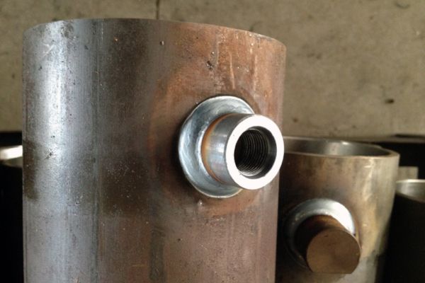
Welded cylinders use compact, heavy-duty port ports integrated into forged end caps, making them ideal for high-pressure, tight-clearance farm loader environments. Tie-rod models feature adjustable, bolt-together designs that work well for standard industrial applications but are more prone to structural stretching under extreme pressure spikes.