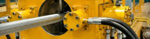
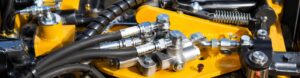
One-piece fitting leak prevention depends on controlling two separate joints: the crimped hose interface and the connection to the equipment port. A retained ferrule reduces one picking error, but it cannot correct the wrong hose, thread, seat, seal, crimp setting, or installation method. The following seven checks help hose assembly technicians find those risks before pressure turns a small mismatch into rework, contamination, downtime, or injury.
Check 1: Confirm the Exact Hose-and-Fitting Combination
Match series and construction, not only dash size
The fitting series must be approved for the exact hose manufacturer, series, construction, and size. Two hoses with the same nominal inside diameter can differ in tube material, cover thickness, reinforcement layers, wire dimensions, and outside diameter. Those differences change how the hose grips the stem and deforms beneath the ferrule.
A one-piece fitting normally combines or permanently retains the stem and ferrule as one assembly component. This arrangement reduces the chance of selecting a separate ferrule from another product family, but it does not make the fitting compatible with every hose of the same dash size. Confirm the combination with current manufacturer data rather than stem fit, ferrule appearance, or an old cross-reference.

Check the application limits of the complete assembly
Pressure suitability is controlled by the lowest-rated applicable component and by actual service conditions. Check working pressure, impulses, temperature, fluid, bend radius, movement, vibration, abrasion, external loads, and environmental exposure. A fitting rating considered alone does not establish the rating or life of the finished hose assembly.
Material, plating, and seal selection must also suit the fluid and environment. Stainless steel is not automatically the correct choice for every corrosive service, and salt-spray performance does not directly predict field life. Where equipment approval, fire resistance, electrical conductivity, cleanliness, or regulatory requirements apply, include them before releasing components to production.
Check 2: Identify the Thread and the Real Sealing Surface
Measure the connection instead of trusting appearance
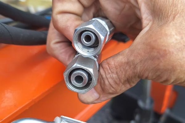
Similar-looking hydraulic threads can belong to different systems. Confirm male or female form, outside or inside diameter, pitch or threads per inch, straight or tapered form, and connection standard. NPT/NPTF, BSPP, BSPT, JIC, SAE 45-degree, ORFS, ORB, metric, DIN, and JIS connections must not be declared interchangeable because they start together or look alike in a photograph.
Use suitable calipers and a thread-pitch gauge on clean, undamaged threads, then compare the results with reliable dimensional data. For tapered threads, measure at more than one point where practical. Photographs help with preliminary screening and documentation, but coatings, wear, dirt, perspective, and small dimensional differences make them insufficient for final selection.
Locate where the connection is designed to seal
Threads may tighten a joint while a cone, flare, O-ring, flange face, bonded seal, or other surface contains the fluid. Check the seat angle and condition, O-ring size and material, groove, mating nose, and alignment as applicable. A nut that threads on smoothly can still leave incompatible seats separated or loaded on a narrow, damaged edge.
Tapered pipe threads require confirmation of the exact thread form and specified sealing procedure. Thread sealant cannot convert BSPT to NPT, repair a cracked port, or fix an incorrect pitch. It also does nothing for a damaged flare, ORFS face, O-ring groove, or other non-thread sealing interface.
Check 3: Inspect Components Before Assembly
Reject damage that can become a leak path
Inspect the fitting before insertion. Threads should be free from dents, galling, flattened crests, heavy corrosion, and embedded debris; sealing faces should have no scratches, impact marks, coating buildup, or burrs in the contact area. Check that the ferrule is correctly retained, the stem is not bent, and identification agrees with the work order.
Inspect the hose as well. Reject material with cuts, crushed reinforcement, contamination, abnormal hardness, exposed wire, ovality beyond applicable limits, or storage damage. Cut the hose square with suitable equipment because an angled or ragged cut can interfere with insertion, create debris, and leave uneven support beneath the ferrule.
Keep the fluid path and seals clean
Contamination can hold a sealing face open, damage a seal during tightening, or enter the hydraulic system. Clean the hose bore and components using the specified process and protect finished ends with suitable caps or plugs where cleanliness requirements call for them. Do not wipe precision sealing surfaces with material that leaves fibers or introduces incompatible chemicals.
Install only the specified seal in good condition. An O-ring with the correct apparent diameter may still have the wrong cross-section, compound, hardness, or temperature and fluid capability. Avoid stretching, twisting, cutting, or lubricating a seal unless the applicable procedure defines how it should be installed.
Check 4: Follow the Complete Crimp Specification
Control preparation, insertion, dies, and diameter
Crimp diameter is one part of a complete process. Current instructions for the exact hose-and-fitting combination may also specify cut length, skiving or no-skive preparation, cleaning, insertion depth, die set, crimper setup, measurement position, and dimensional tolerance. There is no universal crimp diameter or machine setting for all one-piece hydraulic hose fittings.
Mark the specified insertion depth on the hose and insert the stem fully without contaminating it. The mark gives a visible indication if the hose backs away before crimping. If skiving is required, remove only the specified cover or inner material with the prescribed tooling; unauthorized skiving can damage reinforcement, while skipping a required skive changes the designed grip.
Measure the result rather than trusting the setting
The crimper setting is an input, not proof of the finished dimension. Die wear, machine condition, component tolerances, setup mistakes, and spring-back can shift the result. Measure the crimp at the prescribed locations and by the specified method with suitable calibrated equipment, then compare it with the target and tolerance in the applicable data.
Do not repeatedly crimp an uncertain assembly unless the manufacturer’s procedure explicitly allows correction. Extra compression may damage reinforcement, deform the stem, restrict the bore, or create a ferrule-edge stress concentration. Quarantine an out-of-tolerance part, investigate the setup and components, and use the authorized disposition process.
Check 5: Inspect the Finished Assembly Before Installation
Separate crimp defects from connection-end defects
Confirm that the ferrule sits in the intended position and the insertion mark indicates full engagement. Look for cracked plating, displaced metal, abnormal ferrule shape, exposed wire, cuts, bulging, heat damage, or a hose that is visibly cocked on the stem. Verify elbow orientation and overall length before the assembly reaches the machine.
Then inspect the opposite end of the leak path: threads, seats, flange faces, and seals. Protective plugs should not damage or conceal sealing surfaces. This two-zone inspection matters because reducing the crimp diameter cannot repair a scratched seat, and applying more installation torque cannot correct incomplete hose insertion.
Use testing only under a controlled procedure
Some assemblies or applications require proof, pressure, cleanliness, conductivity, or other testing; others do not authorize a generic shop test. Follow the applicable equipment, hose, and fitting requirements for test medium, pressure, duration, temperature, guarding, acceptance criteria, and documentation. Never invent a test value from working pressure or copy a procedure from an unrelated assembly.
Testing must occur in a protected area with suitable equipment and controlled access. Do not handle or approach a pressurized assembly to investigate a suspected leak. If a result is outside the acceptance criteria, depressurize safely, quarantine the assembly, and preserve enough evidence to identify the cause.
Check 6: Install Without Damaging the Joint
Prevent twist, side load, and poor alignment
Route the hose so tightening the connection does not twist the assembly. A printed hose layline can help reveal rotation, but use the installation limits and routing practices applicable to the product. Twisting places stress into the reinforcement and can rotate an elbow away from its intended position, producing early failure even when the crimp and sealing face were initially correct.
Align mating connections before tightening and support the assembly so its weight does not side-load the port. Maintain the specified bend radius and avoid a sharp bend immediately behind the ferrule. Where motion occurs, provide enough length and routing freedom for the hose to flex in its intended plane without rubbing or pulling on the fitting.
Tighten the sealing system by its specified method
Different connection systems require different assembly controls. A flare, face seal, flange, straight-thread O-ring connection, and tapered pipe thread do not share one universal torque or turn count. Use the current procedure for the exact connection, size, material, coating, seal, and mating component, including backup-wrench requirements where specified.
More torque is not a general cure for leakage. Over-tightening can flatten a flare, extrude an O-ring, crack a port, distort a swivel nut, gall threads, or make correct seating impossible. If a joint does not align or engage normally, stop and identify the interference rather than forcing it together.
Check 7: Diagnose and Document Before Replacing Parts
Find the leak origin after safe shutdown
Before inspection, shut the equipment down, isolate it, release hydraulic pressure and stored energy, and follow the equipment and component manufacturers’ safety procedures. Never use a hand to search for a pinhole leak because high-pressure fluid can penetrate skin. Use an authorized detection method only after the area is made safe.
Clean the depressurized area as permitted, then determine whether fluid originated at the hose-to-ferrule interface, the threaded or seated connection, a seal, the hose body, or another component above it. Oil travels along hoses and fittings, so the wettest visible point may not be the source. Preserve the assembly and installed orientation until the initial examination is complete.
Let the failure location direct the next checks
| Observed leak or damage | Checks to prioritize | Unsafe shortcut to avoid |
|---|---|---|
| Fluid between hose and ferrule | Hose/fitting compatibility, insertion, crimp dimensions, stem and ferrule condition | Applying sealant outside the ferrule |
| Fluid at flare or seat | Seat standard, angle, damage, alignment, tightening method | Increasing crimp compression |
| Fluid at O-ring connection | Correct seal, groove, face, extrusion, contamination, installation | Substituting a similar-looking O-ring |
| Fluid at tapered pipe thread | Exact thread forms, engagement, port damage, specified sealant and procedure | Forcing mismatched threads together |
| Rupture beside ferrule | Over-crimp, skive damage, bend radius, flexing, hose compatibility | Reproducing the old assembly without investigation |
| Hose or fitting pull-out | Combination approval, insertion, diameter, routing load, pressure conditions | Recrimping the failed components |
Record the hose legend, fitting part numbers, crimp specification, measured result, machine, dies, seal, port identity, installation orientation, and service conditions. Photograph the complete routing and failure area before teardown. Good records distinguish an isolated damaged seal from a repeated selection, crimping, routing, or equipment problem.
Put the Seven Checks Into a Workable Shop Routine
Use hold points where errors are still inexpensive
The checks work best when placed before irreversible steps. Verify identification and compatibility before cutting hose; verify preparation and insertion before crimping; measure before releasing the assembly; and inspect routing before pressurizing equipment. A short hold point is cheaper than trying to identify mixed components after the ferrule has been compressed.
For a replacement, quotation, or technical review, prepare the following information:
- Hose manufacturer, exact series, hose ID or dash size, hose legend, and intended fitting series.
- Fitting part numbers, style, orientation, material, finish, male or female form, thread diameter, pitch, taper, seat, and sealing method.
- Current crimp data, including preparation, insertion depth, dies, diameter, tolerance, and measurement method, plus crimper identification.
- Working pressure, impulses, temperature, fluid, equipment function, routing, movement, vibration, environment, and failure consequences.
- Clear photographs of the fitting, hose markings, sealing surface, mating port, installed routing, and leak location after safe depressurization.
Prevent Leaks by Verifying Both Sides of the Fitting
Reliable one-piece fitting leak prevention comes from verifying the hose interface and the equipment connection as separate but equally necessary joints. Match the exact hose and fitting series, identify the thread and seal, inspect clean components, follow current crimp data, measure the finished assembly, install it without stress, and document the result. Before the next assembly, gather the component identities, application conditions, crimp procedure, port details, and inspection evidence rather than relying on appearance or the lowest replacement cost.
Frequently Asked Questions
Does a one-piece fitting eliminate ferrule mismatch?
It removes the need to choose a separate ferrule for that fitting, reducing one type of picking error. It does not guarantee that the complete fitting series matches the selected hose or crimp specification.
Can I stop a connection leak by crimping the ferrule smaller?
No; a leak at the thread, seat, flange face, or O-ring must be corrected at that interface. Additional crimping may damage the hose reinforcement or stem without affecting the connection-end seal.
Should every hydraulic hose assembly be pressure-tested?
Testing depends on the applicable product, equipment, organization, and safety requirements. When required, use a defined procedure with suitable guarded equipment and stated acceptance criteria rather than a generic shop value.
Can thread sealant repair a leaking flare connection?
No; a flare connection seals at its mating seats, not through sealant on the threads. Confirm compatible seat geometry, surface condition, alignment, and the specified tightening procedure.
Can a hose assembly be reused after the fitting has leaked?
Reuse depends on the identified cause, component condition, and applicable manufacturer procedures. Do not recrimp, reseal, or reinstall it until it has been safely removed, inspected, and given an authorized disposition.