“1-inch flange” is not enough information to recommend a Parker 43 flange replacement because it identifies only a nominal connection size—and sometimes not even which component that size describes. It does not establish whether the port is SAE Code 61 or Code 62, what hose ID is required, whether the fitting is straight or angled, or which hose and crimp specification must be used. The phrase can therefore lead to a fitting that looks close but cannot bolt up, cannot handle the application, or cannot be assembled safely. A reliable recommendation starts by converting the verbal description into a complete, measurable specification.
One Inch Can Describe More Than One Feature
Flange size is not automatically hose size
The first problem is semantic: “one inch” may refer to the nominal flange size, the hose inside diameter, the port bore, or a dimension someone measured on the old part. Those values are related only in some configurations. A flange fitting can use a 1-inch flange head with a smaller hose, and a 1-inch hose can terminate in a flange head of another nominal size when the catalog offers a reducer combination. Unless the requester states what was measured and where, the inch value cannot be placed in the correct field of a part number.
Parker part numbers expose the missing distinction
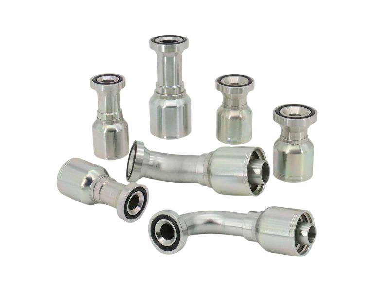
Both 11543-16-12 and 11543-16-16 are straight SAE Code 61 flange-head fittings with a 1-inch flange, but the first is listed for 3/4-inch hose ID and the second for 1-inch hose ID. The base series and flange size therefore do not identify the hose end. A recommendation made from “Parker 43, 1-inch flange” can select the wrong stem and ferrule combination even before pressure, material, orientation, and physical clearance are considered.
The Flange Series Must Be Identified First
Code 61 and Code 62 are different interfaces
SAE Code 61 and Code 62 four-bolt flange connections are separate dimensional systems, commonly associated with ISO 6162-1 and ISO 6162-2. They may look similar in a photograph, but the flange-head outside dimensions, thickness, clamp and bolt pattern are not the same. That difference is enough to prevent correct clamping or O-ring compression, so the pressure series cannot be guessed from nominal size.
“Parker 43” does not resolve the pressure series
The 43 Series name identifies a family of permanent crimp-style hose fittings, not a universal flange pattern. If the existing machine port is Code 62 or another flange system, the answer may require a different fitting family rather than a nominally similar 43 Series part. This is why a cross-reference should begin with the port standard and the complete original part number, not with a brand family name followed by an inch value.
| Required decision | What “1-inch flange” tells you | What remains unknown | Risk if guessed |
| Flange interface | A possible nominal size | Code 61, Code 62, or another pattern | Head, clamp, or bolts do not fit correctly |
| Hose connection | Nothing certain | Hose ID, construction, and fitting series | Stem or ferrule does not match the hose |
| Fitting geometry | Nothing | Straight, 22.5°, 45°, 67.5°, 90°, drop, and envelope | Hose cannot follow the required route |
| Application rating | Nothing | Pressure, impulse, temperature, fluid, and environment | Assembly is unsuitable for service |
| Assembly process | Nothing | Crimper, dies, crimp diameter, and preparation | Leakage, hose damage, or fitting separation |
A Flange Replacement Has Several Independent Interfaces
Confirm the flange head and sealing system
A four-bolt hydraulic flange connection normally seals with an O-ring at the flange head against the port face; the bolts and clamp halves retain the head and create the specified compression. Identification should therefore include the head OD, head thickness, bolt-hole spacing at the mating port or clamp, port-face condition, O-ring groove location and dimensions, and the applicable standard. Do not treat the clamp as proof of the head series, because loose hardware can be mixed during maintenance.
Confirm the hose end as a separate system
After identifying the flange interface, verify the hose manufacturer, hose series, construction, ID or dash size, and the fitting series approved for that hose. A one-piece fitting generally retains the stem and ferrule as one assembly, which can reduce errors caused by selecting a separate ferrule from the wrong family. It does not make the fitting compatible with every hose of the same nominal ID, and it does not supply a universal crimp diameter. The valid hose-and-fitting combination, preparation method, insertion depth, dies, crimper settings, and inspection limits must come from current data for the exact components being assembled.
Shape and Installed Geometry Can Still Reject the Part
Straight and elbow styles are not routing equivalents
Even after the flange code and hose size are known, the fitting style remains open. Parker’s 43 Series Code 61 listings include straight and several angled forms, and an old machine may depend on a specific elbow angle and drop to keep the hose away from a frame, cylinder, guard, or hot surface. Replacing an elbow with a straight head and forcing the hose to turn immediately can violate the hose’s minimum bend radius or load the flange connection sideways. Replacing one elbow with another that has a different centerline or body envelope can also create interference, so use the one-piece fitting cross-referencing process to organize rather than shortcut the comparison.
Orientation and envelope require an installed check
The required geometry includes the angle, drop, flange-head-to-hose centerline, overall length, ferrule envelope, hose OD, and straight section before the first bend. It also includes the clocking needed to aim the hose when the head is held by the split clamp. A loose part placed near the port does not reproduce the installed assembly because the finished crimp, hose stiffness, clamp position, and neighboring motion determine the actual occupied space. Clearance should be checked on an exact sample assembly or an accurate fixture through the equipment’s full operating range.
Build a Reliable Identification From the Old Assembly
Collect evidence before selecting a candidate
Stop the equipment, isolate the energy sources, release hydraulic pressure and stored energy, and follow the equipment manufacturer’s maintenance procedure before removing or measuring a hose assembly. Clean the old connection without damaging the flange face or O-ring groove, then record the full part number and any readable markings. Photographs are useful for documenting shape and condition, but they cannot prove the standard or pressure suitability by themselves. A structured one-piece fitting photo and detail checklist prevents the most important views from being omitted.
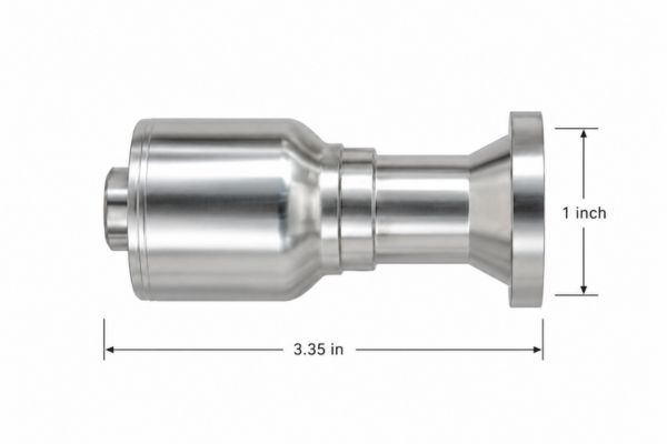
Collect these identification fields:
- Full original part number, equipment model, assembly location, and any controlled drawing reference.
- Nominal flange size, suspected code, head OD and thickness, port or clamp bolt spacing, and O-ring groove details.
- Hose manufacturer, series, hose ID or dash size, hose OD, and readable layline information.
- Straight or elbow style, angle, drop, overall dimensions, orientation, and available clearance.
- Working pressure, temperature, fluid, impulse or vibration conditions, and material or finish requirement.
- Crimping machine, dies, preparation method, and the current crimp-data source intended for the replacement.
Use dimensions to confirm, not invent, the standard
Compare the measured values with current drawings for the suspected standard and exact fitting suffix. Measurements should confirm a documented candidate; they should not be rounded until they resemble the nearest catalog size. Check several independent features, because a worn head, compressed O-ring, damaged clamp, or inaccurate tape measurement can mislead a single-dimension comparison. If Code 61 versus Code 62 remains uncertain, do not recommend a part from pressure alone—obtain the equipment port specification, original assembly record, or an authoritative drawing.
Approve a Complete Assembly, Not a Catalog Description
Screen the candidate in controlled stages
The candidate should pass a document review, dimensional inspection, hose-and-crimp review, and installed fit check before it becomes an approved replacement. A cross-reference is only a search aid; it does not prove that two products are fully interchangeable. For a low-risk sample, use the exact production hose, fitting, crimper, dies, and current assembly procedure, then record the finished crimp dimensions and inspection results. Never use a mismatched flange or improvised hardware to restore operation while waiting for clarification.
A practical approval record should show:
- The complete candidate part number and drawing revision.
- The confirmed flange standard, nominal size, dimensions, O-ring, clamps, bolts, and tightening procedure reference.
- The approved hose series and size, fitting family, assembly method, and crimp inspection limits.
- The pressure, temperature, fluid, material, finish, routing, and clearance requirements.
- The sample result, deviations, decision owner, and conditions that require reapproval.
An orderable recommendation should no longer depend on verbal interpretation. Its supporting record must show which number describes the flange, which describes the hose, how the connection seals, how the fitting is oriented, and which controlled assembly data applies. This approach also protects future replenishment: a later parts-counter employee can retrieve the approved configuration rather than repeating the same measurements during another outage. If any safety-critical parameter remains unknown, the correct result is “identification incomplete,” not the closest-looking 43 Series flange.
A focused clarification request
Ask for the smallest set of information that closes the actual identification gaps. Avoid responding with a long catalog or a list of possible parts, because that shifts the technical decision back to someone who supplied only a vague size. The request should make clear that flange size, flange code, and hose size are different fields and that a photograph supplements rather than replaces measurements.
Request the following:
- “Does 1 inch refer to the flange size or the hose ID?”
- “Is the flange confirmed as SAE Code 61, Code 62, or another standard?”
- “What is the complete existing part number, and are all suffixes readable?”
- “What are the flange-head OD and thickness, bolt spacing, O-ring details, and fitting angle?”
- “What hose manufacturer, series, dash size, and crimp specification are currently used?”
- “What are the working pressure, temperature, fluid, machine location, and clearance limits?”
Conclusion
A 1-inch flange cannot identify a Parker 43 flange replacement because nominal size answers only one part of a multi-interface decision. The recommendation must also establish the flange standard and pressure series, exact head dimensions and seal, complete part-number suffix, hose construction and ID, fitting shape and orientation, material and finish, application conditions, and valid crimp data. Parker’s own catalog shows why this matters: a 1-inch Code 61 flange head can be paired with more than one hose size, while Code 61 and Code 62 use different geometry. Ask for measured evidence and current drawings, then approve the exact finished hose assembly instead of assuming that brand family plus inch size proves interchangeability.
FAQ
Can a photo distinguish a 1-inch Code 61 flange from Code 62?
A clear, scaled photo can support preliminary screening, but final identification needs controlled dimensions, port information, markings, and the applicable drawing.
Does a 1-inch flange require a 1-inch hose?
No. Cataloged flange fittings can pair the same nominal flange size with different hose IDs, so both values must be stated independently.
Can the system pressure alone identify Code 61 or Code 62?
No. Pressure is an application requirement, not reliable physical identification; confirm the port standard and dimensions before selecting the fitting.
Are the O-rings and split clamps interchangeable between both codes?
Do not assume so, because the flange systems use different geometry and hardware requirements; select seals, clamps, and bolts from current data for the confirmed code and size.
If the old fitting says 43 Series, is the replacement decided?
No. The family reference must be combined with the complete suffix, flange code and size, hose series and size, shape, material, application limits, and crimp specification.