You send an old hydraulic hose to a supplier. The threads and length are measured, and the replacement looks almost identical. After installation, however, an elbow points toward the frame, the hose becomes tight at full cylinder extension, and the machine moves more slowly. The problem may not be hose quality. More often, the order failed to define the assembly’s function, flow, pressure, internal diameter, connection details, measurement points, and fitting orientation.
Why “Make It Like the Sample” Is Not a Complete Specification
What an old hose can reveal
An old assembly can provide useful physical information, including:
- Approximate hose size
- Fitting types
- Overall shape and length
- Protective sleeves or guards
- Fitting orientation
- Visible markings
The sample can also help the supplier identify whether the assembly uses straight, 45-degree, or 90-degree fittings. If its markings remain legible, they may indicate the hose family, size, pressure class, or applicable standard.
This makes the old hose a valuable reference, but not a complete specification.
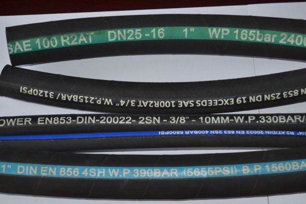
What the sample cannot reliably show
A supplier cannot determine maximum flow, pressure peaks, impulse frequency, allowable backpressure, or oil temperature by looking at an old hose.
The sample may also have stretched, twisted, softened, shortened, or permanently deformed during service. Its identification markings may be damaged, and one of its fittings may have been replaced during an earlier repair.
Two hoses with similar outside diameters can have different bores, reinforcement structures, working-pressure ratings, and minimum bend radii. The old assembly should therefore support the purchase specification rather than replace it.
Identify the Hose’s Function Before Selecting Its Size
Pressure and suction lines have different priorities
A pressure line carries oil from the pump or control valve to an actuator. Selection must consider normal working pressure, transient pressure peaks, impulse cycles, oil temperature, external heat, vibration, and movement.
A hose that tolerates steady pressure may not be suitable for a circuit exposed to repeated pressure impulses.
A pump suction hose has a different task. It must resist collapse under negative pressure while keeping inlet restriction low. An undersized suction hose can increase fluid velocity and pressure loss, contributing to pump noise, poor filling, or cavitation risk.
The hose construction must therefore provide adequate vacuum resistance as well as sufficient flow area.
Return and case drain lines still require careful sizing
A return line normally operates at lower nominal pressure than a main pressure line. However, it may still experience backpressure, temperature rise, and pressure spikes.
An undersized return hose, restrictive fitting, clogged filter, or small quick coupling can increase resistance and change machine behavior.
A pump or motor case drain may carry limited flow, but its allowable backpressure can be very low. A small hose bore or restrictive fitting may create enough pressure to affect shaft seals or internal component operation.
A useful request description might say:
This assembly is a pressure line from the valve block to the rodless side of the boom cylinder. It moves through the full cylinder stroke, passes through one clamp, and runs close to a sharp frame edge.
That sentence is more useful than “1/2-inch high-pressure excavator hose.”
Do Not Use Outside Diameter as a Substitute for Bore Size
Use flow velocity as an initial screening method
Two hoses can appear similar while having different internal flow areas. The inner tube, reinforcement layers, and outer cover all affect outside diameter. The fitting insert may reduce the passage further.
A preliminary size check can use average fluid velocity:
v = Q / A
For a circular flow passage:
A = πd² / 4
Where:
v is average fluid velocity
Q is volumetric flow
A is the flow area
d is the actual internal diameter
Assume a maximum flow of 40 L/min. The following figures demonstrate the method and are not performance guarantees for a particular hose product.
| Assumed actual bore | Average velocity | Initial interpretation |
| 9.5 mm | 9.41 m/s | Relatively high; check a larger bore and allowable pressure loss |
| 12.7 mm | 5.26 m/s | More moderate, but the complete circuit still requires verification |
| 15.9 mm | 3.36 m/s | Lower velocity, but the hose requires more installation space |
Balance pressure loss against size and flexibility
A larger bore normally reduces velocity and straight-hose friction. It may help lower pressure loss and heat generation, but the hose will usually be heavier, more expensive, and harder to route. It may also have a larger minimum bend radius.
A smaller hose can fit into a confined space more easily, but higher velocity and restriction may affect actuator speed or system efficiency.
Average velocity is only a screening calculation. Formal verification should also consider:
- Oil viscosity in hot and cold conditions
- Total hose length
- Fitting and adapter bores
- Elbows and bends
- Filters
- Valves
- Quick couplings
- Acceptable circuit pressure loss
If a machine becomes slower after hose replacement, the actual flow passage should be checked—not just the printed hose size or outside diameter.
Evaluate Pressure at the Complete Assembly Level
The lowest-rated compatible component sets the limit
A hydraulic hose assembly normally includes the hose, end fittings, seals, crimped interfaces, and any installed adapters or couplings.
The completed assembly’s allowable working pressure is limited by its lowest-rated compatible component. A high-pressure hose does not make an unsuitable fitting, seal, or crimp connection safe.
Compatibility is equally important. A hose and fitting may each have acceptable individual ratings but still be unsuitable as a combination if they have not been designed and validated for use together.
The supplier should confirm the complete hose-and-fitting system rather than combining parts based only on nominal size.
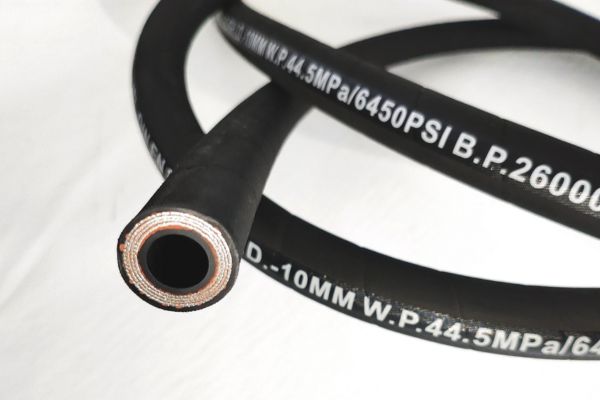
Do not treat a product-page maximum as a universal rating
A product page may display a broad pressure range covering several sizes or constructions. The highest value may apply only to a smaller bore or a specific reinforced version.
For example, a hose family may list different working pressures according to size. That does not mean every bore, fitting combination, temperature, and finished assembly can use the maximum value shown.
If the machine requires continuous operation at 28 MPa, a screenshot showing “35 MPa” is insufficient. The supplier should identify:
- Exact hose construction and size
- Working pressure for that size
- Compatible fitting series
- Crimp specification
- Temperature limits
- Relevant impulse performance
- Completed assembly rating
- Required inspection or test records
Specify Both Fittings by Their Sealing Interfaces
Thread size alone does not identify the connection
Descriptions such as “1/2-inch fitting,” “JIC,” “BSP,” or “metric fitting” are incomplete.
Each hose end should record:
- Thread standard
- Thread diameter
- Thread pitch
- Male or female configuration
- Fixed fitting or swivel nut
- Straight, 45-degree, or 90-degree body
- Fitting material and surface treatment
- Seal material, where applicable
- Mating port drawing or part number
The same thread description may be associated with different sealing methods. The true connection cannot be confirmed until both the thread and sealing interface are identified.
Threads can engage while the sealing faces remain incompatible
Hydraulic connections may seal through a 37-degree flare, 30-degree seat, 24-degree cone, 60-degree cone, face-seal O-ring, straight-thread O-ring, tapered thread, or flange interface.
Two parts may screw together without forming the correct seal. The installer may then apply additional torque or sealant without resolving the mismatch.
Useful identification photographs should show:
- The sealing face directly from the front
- A side view of the complete fitting
- Thread diameter measurement
- A thread-pitch gauge in position
- The mating machine port
- Visible markings or part numbers
Whenever possible, use the mating port drawing or original component number rather than relying only on visual comparison.
Decide Whether to Use Direct Fittings or Adapters
Adapters improve standardization but add connections
Adapters can protect an expensive valve, pump, or cylinder port from repeated hose replacement. They may also help standardize inventory by allowing several machines to use a smaller group of common hose assemblies.
This can simplify emergency replacement and reduce the number of special hoses that must be stocked.
The trade-off is that an adapter creates another joint, adds installation length, and introduces another possible leakage path. Its internal bore may also be smaller than the hose bore, creating a local restriction.
Direct custom fittings reduce joints but limit interchangeability
A hose manufactured with the exact machine-side fitting can be more compact and eliminate an extra connection. This is useful where clearance is limited or where a longer adapter assembly would interfere with nearby components.
However, a special fitting reduces interchangeability and may increase replacement lead time.
The decision should consider:
- Available installation space
- Port value and replacement risk
- Required flow passage
- Hose replacement frequency
- Local inventory
- Emergency availability
- Maintenance practices
The objective is a safe and serviceable connection, not simply the fewest components.
Define Finished Length and Measurement Points
The same stated length can produce different assemblies
“900 mm long” is not a complete instruction.
One person may measure between the ends of the nuts. Another may measure between the sealing faces. A third may record only the visible flexible hose section. All three orders may state 900 mm while producing different assemblies.
The drawing must show the measurement endpoints and required tolerance.
A common assembly calculation can be represented as:
Hose cut length = Finished assembly length − (C1 + C2)
Assume the required finished length is 900 mm, while the manufacturer dimensions for the selected fittings are 35.1 mm and 36.1 mm:
900 − 35.1 − 36.1 = 828.8 mm
This is only an illustrative cut length. Actual fitting dimensions, insertion depth, crimp-related changes, tolerances, and final inspection methods depend on the approved assembly system.
Verify length through the complete machine movement
The hose must fit when the machine is operating, not only when it is parked.
Check the routing with the cylinder fully retracted, fully extended, and at intermediate positions. Also inspect maximum steering, articulation, boom movement, suspension travel, and any service position relevant to the machine.
The assembly should not:
- Become tight
- Rub against a sharp edge
- Contact a heat source
- Buckle
- Fall below its minimum bend radius
- Pull sideways on a port
- Become trapped between moving components
Adding excessive length is not a universal solution. A hose that is too long may sag, rub, or become caught in the machine.
Define Elbow Orientation with a Repeatable Method
Use one fitting as the zero-degree reference
When one or both ends use elbows, angular orientation becomes part of the assembly specification.
Instructions such as “both elbows point upward” are unreliable because the meaning changes when the hose is turned over or viewed from the opposite end.
A repeatable instruction should:
- Identify the reference fitting
- Set that fitting to 0 degrees
- Define the viewing direction
- State clockwise or counterclockwise rotation
- Specify the second fitting’s angle
- Include an angular tolerance
A simple drawing or orientation diagram is normally the clearest solution.
Never twist the hose to correct an orientation error
An incorrectly oriented elbow may force the installer to twist the hose until the fitting aligns with the port.
This can preload the reinforcement, distort the natural bend, and alter how the hose moves during machine operation. The resulting damage may not be immediately visible.
The hose should enter each connection naturally. It should not act as a torsion spring to compensate for an incorrect assembly angle. If the fitting cannot align without twisting the hose, the orientation should be corrected before the machine returns to service.
Convert Cleanliness and Testing into Acceptance Criteria
External appearance does not confirm internal cleanliness
A hose can look clean while containing rubber particles, cutting debris, wire fragments, dust, or moisture.
These contaminants can damage pumps, valves, proportional controls, and other sensitive hydraulic components.
Where contamination control matters, specify:
- Cleaning method
- Applicable cleanliness target
- Inspection or verification method
- Whether cleaning occurs after final assembly
- End-cap requirements
- Packaging requirements
- Required records
Do not invent a universal cleanliness number when the machine manufacturer or project specification has not provided one. The requirement should reflect the system’s sensitivity and applicable maintenance standard.
“100% pressure tested” needs a defined procedure
A meaningful test requirement identifies:
- Test medium
- Test pressure
- Hold time
- Test temperature, where relevant
- Acceptance criteria
- Safety isolation
- Required test record
- Applicable procedure or standard
A proof-pressure test may identify certain leaks or assembly defects, but it does not replace correct hose selection, fitting compatibility, verified crimp dimensions, impulse validation, cleanliness control, or installation inspection.
Testing is one part of assembly assurance. It cannot compensate for missing design information.
Use a Complete Hydraulic Hose Assembly RFQ
Record the operating and installation conditions
A practical request for quotation should identify:
- Machine type and model
- Hose function
- Connection points
- Maximum continuous flow
- Normal working pressure
- Maximum pressure peak
- Oil type
- Oil and ambient temperatures
- Static or moving installation
- Required internal diameter
- Minimum bend radius
- Abrasion, weather, flame, or chemical exposure
- Clamp positions, sharp edges, and nearby heat sources
For case drain or other sensitive circuits, include the maximum allowable backpressure.
Define the finished assembly and quality requirements
For each fitting, record:
- Thread standard and size
- Thread pitch
- Male or female configuration
- Fixed or swivel design
- Fitting shape
- Sealing interface
- Material and surface treatment
- Mating port information
Also specify:
- Finished assembly length
- Measurement endpoints
- Length tolerance
- Elbow reference direction and angle
- Cleaning requirements
- End caps and packaging
- Inspection or pressure-test requirements
- Identification and traceability
- Quantity and delivery schedule
Attach the old hose, photographs, and drawings to this information. Do not use the sample as a substitute for the specification.
Conclusion
A replacement hose can copy the old assembly visually and still fail because its bore, sealing interface, length reference, elbow orientation, or routing behavior is wrong. A reliable order defines the hose’s function, flow, pressure, temperature, bore, fittings, finished length, movement, cleanliness, and testing requirements. This turns “make one like the old hose” into a repeatable specification that a qualified supplier can manufacture and inspect.