A poor pump-inlet fitting choice can restrict flow, admit air, distort the hose, and leave a pump noisy or starved even though the line never develops high pressure. Selecting one-piece fittings for suction line applications therefore requires more than matching a thread and hose dash size. The fitting passage, sealing interface, hose vacuum resistance, route, bend geometry, and reservoir connection must work as one inlet path.
Treat the Pump Inlet as a Complete Flow Path
The correct fitting is the one that helps the complete inlet path meet the pump manufacturer’s requirements without creating an air-leak path or local restriction. A pressure rating alone says little about those two suction-side duties.
Begin with the system requirement
Collect the pump model, required inlet condition, expected flow, speed range, fluid, temperature range, reservoir arrangement, elevation, and operating positions. Then map the line from the reservoir outlet to the pump port, including valves, strainers, adapters, fittings, hose, and bends. Each element consumes part of the available inlet margin, so judging a fitting in isolation can hide the actual bottleneck.
Cold fluid, a clogged strainer, a long hose, a high-mounted pump, or poor reservoir venting may make an otherwise acceptable route restrictive. Transient demand can also differ from steady operation. Use current equipment and pump data to define acceptable conditions, and state how the condition will be measured during validation rather than relying on a generic suction-line rule.
Understand what one-piece construction changes
A one-piece hose fitting has a stem and ferrule preassembled, attached, or retained together, with details varying by series. It can reduce separate ferrule selection and handling errors. It does not establish hose compatibility, vacuum capability, internal passage, thread identity, seal performance, or a correct crimp.
Selection still requires an approved hose-and-fitting combination. Confirm the hose manufacturer, series, construction, ID, fitting series, ferrule design, assembly equipment, die set, insertion method, and current crimp specification. A shared dash size identifies nominal sizing conventions; it does not prove that two hose and fitting products can be assembled safely.
Keep Restriction Low Without Guessing at Size
Suction fittings should provide the passage and geometry required by the actual inlet design. Choosing by port thread alone can leave a reduced bore, abrupt transition, or elbow that becomes the controlling restriction.
Compare the effective passage
Review the minimum internal passage through the stem, swivel, adapter, elbow, and mating port, not just the hose ID printed on a drawing. A large hose connected through a smaller internal feature may not deliver the expected benefit. Conversely, increasing nominal size without checking the pump port, route, and hose behavior can add bulk without solving the limiting condition.
Ask for dimensioned product data and compare every transition. Consider whether the connection includes a sleeve, insert, seal support, or swivel feature that changes the flow area. Do not infer bore from the hex size or outside appearance. Where calculations or simulations are used, verify their assumptions against the installed line and the fluid condition.
Account for geometry and surface condition
Abrupt direction changes and closely spaced restrictions can affect inlet performance differently from a straight, gradual route. Internal damage, contamination, excess approved sealant, or a displaced seal can further reduce the passage. Inspection should therefore cover both selected geometry and assembly cleanliness.
Do not reduce a fitting or hose merely to gain clearance until the responsible designer verifies the resulting restriction and hose requirements. A compact part can move the problem from packaging to pump reliability. Record the selected passage dimensions and connection stack so a later replacement does not introduce an unnoticed reduction.
Control Every Possible Air-Ingress Path
A suction connection may draw air without leaking visible oil. The sealing method and assembly condition must therefore be identified at every joint between the reservoir and pump.
Verify threads, seats, faces, and seals
Determine whether sealing occurs on tapered threads, a flare or cone seat, a flat face, an O-ring, a bonded seal, or another designed interface. Confirm the exact connection standard, diameter, pitch or TPI, straight or tapered form, sex, seat, seal location, and mating port. Similar-looking threads or successful engagement do not prove a compatible hydraulic seal.
Inspect seats and faces for scratches, corrosion, dents, embedded debris, and evidence of incorrect tightening. Verify O-ring identity, material, size, groove condition, fluid compatibility, and assembly instructions. Thread sealant is appropriate only where the connection design and current instructions require it; it cannot repair a mismatched seat, damaged face, wrong port, or cross-threaded joint.
Include swivels, adapters, and hose ends
A swivel may make installation easier, but its sealing interface adds another location that must remain airtight under the expected pressure direction, vibration, temperature, and movement. Adapters and reservoir ports add more mating surfaces. Use exact part data for the entire stack rather than approving only the hose fitting.
At the hose end, verify insertion, crimp, cleanliness, and the tube condition behind the ferrule. Side load, a bend too close to the fitting, or an unsupported hose can disturb the joint over time. If the assembly lacks traceable hose, fitting, and crimp data, treat its suction suitability as unverified even when it looks dry.
Match Hose Vacuum Resistance With the Fitting
The fitting cannot prevent a hose from flattening when the hose construction is unsuitable for the inlet condition. Hose vacuum data and fitting compatibility must be reviewed together before the assembly is released.
Check construction, temperature, and condition
Confirm hose ID, reinforcement, tube and cover materials, applicable vacuum rating, temperature limits, fluid compatibility, bend radius, and aging or service restrictions. A hose designed primarily for positive pressure may respond differently to external atmospheric loading. Never substitute another hose solely because its nominal size matches the fitting.
Temperature can change fluid viscosity and hose stiffness, while age, chemical exposure, abrasion, and prior kinking can reduce confidence in the installed hose. Inspect the full length for flattening, soft areas, reinforcement damage, cover separation, or permanent deformation. A suspect hose should not be kept in service by adding clamps or tightening its fittings.
Preserve the approved assembly relationship
Use current data linking the exact hose series to the one-piece fitting series and assembly process. Confirm cutting, skive or no-skive preparation, insertion, die selection, crimp diameter, and final inspection as applicable. No universal crimp value or insertion depth applies across product systems.
The finished assembly must also remain clean. Debris left in the hose, sealant displaced into a passage, or damage created during insertion can affect the pump inlet. Cap cleaned ends until installation, and document the assembly specification so field replacement preserves the verified combination.
Choose Straight or Elbow Fittings From the Route
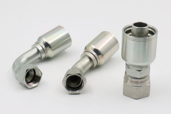
Straight fittings usually offer a simpler flow path, while elbows can prevent an immediate tight hose bend and solve a genuine packaging problem. Neither option is automatically superior; the better choice produces the most natural, serviceable route with acceptable restriction.
Evaluate direction change and bend radius together
A straight fitting followed by a forced hose bend may be worse than a correctly oriented elbow. An elbow with a restricted passage or poor sweep may also be worse than a well-routed straight connection. Compare the complete geometry, including the hose exit direction, required bend radius, body envelope, and distance to the first support.
Use a dimensioned layout rather than rotating a hose into place by force. Check equipment movement, pump vibration, thermal change, and service access. The hose should not be twisted, pulled taut, rubbed against structure, or bent sharply at the ferrule. Confirm that the chosen fitting orientation remains correct through all operating positions.
Check installation and removal space
Elbow sweep, swivel-nut rotation, wrench access, and neighboring components can determine whether a fitting can be assembled correctly. Poor access may encourage under-tightening, excessive torque, wrong tool angles, or damage to a sealing surface. A design that fits only before adjacent parts are installed also creates future service risk.
Review the installation sequence and removal path. Provide enough clearance for approved tools, visual inspection, and cap placement. If a swivel is used to manage orientation, verify its intended function and tightening procedure rather than using it as a substitute for an unsuitable route.
Use Evidence to Make the Final Selection
The selection record should connect each decision factor to a source of evidence. This prevents a convenient part number from becoming an unsupported standard for future repairs.
| Selection factor | Why it matters | Evidence to confirm |
| Pump inlet requirement | Defines the acceptable operating condition | Current pump and equipment data plus planned measurement method |
| Internal passage | Can create a controlling local restriction | Dimensioned fitting, adapter, port, and hose data |
| Sealing interface | Must prevent inward air leakage | Exact connection standard, seal details, and mating-component instructions |
| Hose vacuum resistance | Prevents collapse under expected conditions | Hose-series data for size, temperature, fluid, and vacuum service |
| Hose-and-fitting compatibility | Controls retention and sealing at the ferrule | Approved series combination and current crimp specification |
| Installed route | Changes bend, motion, side load, and serviceability | Layout drawing, movement review, and physical clearance check |
Where evidence conflicts, use the more application-specific requirement and involve the responsible manufacturer or system designer. Do not resolve uncertainty with a larger wrench, more sealant, or a visually similar fitting.
Follow a Pump-Inlet Selection Sequence
A repeatable sequence keeps thread matching from displacing the more important restriction, sealing, hose, and routing questions. Complete the steps before ordering, then verify them again on the installed assembly.
Move from system data to part confirmation
- Define pump, fluid, temperature, operating position, flow demand, and allowable inlet condition.
- Map the reservoir-to-pump path and identify every restriction and sealing interface.
- Select hose construction and ID from current application data, including vacuum resistance.
- Compare straight, elbow, and swivel arrangements using passage and routing evidence.
- Identify the exact thread, seat, seal, O-ring, adapter, reservoir port, and pump port.
- Confirm the hose-and-fitting series and current assembly specification.
- Review clearance, bend radius, movement, supports, cleanliness, and service access.
- Define safe startup measurements, acceptance criteria, and stop conditions.
Do not operate through pump noise, persistent aeration, or visible hose flattening. Stop the equipment, isolate the hydraulic system, release pressure and stored energy, secure raised loads, and follow the equipment manufacturer’s diagnostic procedure.
Record the approved configuration
Document the hose and fitting part numbers, assembly specification, adapter stack, sealing materials, route, support locations, and validation result. Photographs and a dimensioned sketch can help preserve orientation and clearance information, but they do not replace specifications.
The record should also identify alternatives that were evaluated and rejected. That detail prevents a future repair from reintroducing a reduced passage, wrong seal, or hose without verified vacuum resistance simply because it is available locally.
Installation-Readiness Checklist
Before installation, confirm:
- pump inlet requirements and measurement points are defined;
- fitting and adapter passages have been compared with the intended hose ID;
- threads, seats, sealing faces, O-rings, and port standards are fully identified;
- hose series, construction, vacuum data, fluid, and temperature suitability are documented;
- current crimp and inspection data cover the exact hose-and-fitting combination;
- straight or elbow geometry supports the bend radius without torsion or side load;
- wrench access, swivel movement, supports, cleaning, and removal clearance are adequate;
- reservoir outlet, venting, valve, and strainer conditions are included in the review;
- startup acceptance criteria and abnormal-condition stop rules are available.
Conclusion
One-piece fittings can support a reliable suction line when selection begins with the pump inlet rather than the thread catalog. Confirm the allowable inlet condition, map every restriction, compare the fitting’s true internal passage, and identify each sealing interface that could admit air. Match the hose’s vacuum resistance, construction, fluid limits, and bend radius to an approved fitting series and current crimp data. Then check straight or elbow geometry against the real route, movement, support, tool access, and service path. Before approving one-piece fittings for suction line applications, preserve the verified part numbers, assembly specification, connection details, and validation criteria. Abnormal noise, foaming, or hose deformation calls for shutdown and investigation, not tighter fittings or an improvised size reduction.
Frequently Asked Questions
Are elbows always too restrictive for a pump inlet?
No, an elbow may be appropriate when its passage and geometry meet the pump-inlet requirement. It can also prevent a damaging tight hose bend, so compare the complete route rather than rejecting elbows categorically.
Should a swivel be used on every suction line?
No, a swivel is useful only when its exact sealing, passage, orientation, and service characteristics suit the application. It adds an interface that must be identified and kept free of side load.
Can hose ID be selected from the pump port size alone?
No, port size is only one input. Flow demand, inlet limits, hose construction, line length, temperature, fittings, elevation, and reservoir arrangement also affect the decision.
What should be checked at the reservoir connection?
Confirm the outlet geometry, sealing method, internal passage, adapter stack, cleanliness, venting context, and route into the hose. Use equipment-specific data because reservoir layouts and pump requirements vary.
Can a suction air leak remain dry?
Yes, a below-atmospheric line can draw air through a small path without showing an external oil leak. Diagnose the entire inlet route and do not treat a dry joint as proof of airtightness.