Quick disconnect couplings, also called QD couplings, quick disconnect fittings, quick couplers, or QDCs, make liquid cooling and hydraulic systems easier to assemble, service, and maintain. They allow operators to connect or disconnect hoses, manifolds, cold plates, pumps, and other components without rebuilding the entire circuit.
However, a quick disconnect coupling is not automatically leak-free simply because it is new or properly selected.
Many QD leaks are caused during installation. The coupling may be tightened with the wrong torque, connected while the two halves are misaligned, assembled with a damaged O-ring, or placed into service before a proper pressure and leak test has been completed.
The basic rule is simple: A leak-resistant QD installation depends on correct torque, controlled alignment, clean sealing surfaces, healthy O-rings, and a documented commissioning test.
Why Do Quick Disconnect Couplings Leak?
When a quick disconnect coupling leaks, replacing the coupling immediately is not always the best first step. The root cause may be an installation or system-integration problem.
Typical causes include:
- Incorrect tightening torque
- Cross-threading or damaged threads
- O-ring damage during insertion
- Dry installation without compatible lubrication
- Axial, radial, or angular misalignment
- Incomplete engagement of the coupling halves
- Excessive side load from hoses or pipes
- Unsupported hose weight
- Incompatible sealing materials
- Contamination on the coupling face
- Pressure exceeding the coupling’s working rating
- Vibration or movement during operation
- Connecting different coupling series that appear similar but are not interchangeable
Step 1: Confirm That the QD Is Suitable for the Application
Before installation, verify that the coupling is correct for the system.
Check the coupling series
The male and female halves must belong to the same approved series or to a combination specifically listed by the manufacturer. Similar outside dimensions do not prove interchangeability.
Check:
- Manufacturer and product series
- Nominal size
- Valve configuration
- Connection type
- Seal material
- Working pressure
- Test pressure
- Temperature range
- Flow requirement
- Fluid compatibility
- Locking mechanism
- Required mounting hardware
A coupling that connects mechanically may still have an unsafe valve stroke, incorrect sealing geometry, insufficient pressure capability, or poor retention under vibration.
Check the pressure rating
The published working pressure of the coupling should meet or exceed the maximum pressure required by the system. The review should include:
- Normal operating pressure
- Startup pressure
- Shutdown pressure
- Pressure spikes
- Pump dead-head pressure
- Test pressure
- Transient pressure caused by valve closure
The system should not be judged only by its steady-state operating pressure. A coupling exposed to repeated pressure surges may experience accelerated wear even if its average operating pressure appears acceptable.
Check the temperature and fluid
The fluid and the sealing material must be chemically compatible.
Common questions include:
- Is the system using water, water-glycol, hydraulic oil, dielectric coolant, or another fluid?
- What is the minimum startup temperature?
- What is the maximum operating temperature?
- Will the coupling be exposed to temperature cycling?
- Is the coupling stored or transported at a different temperature?
- Can the fluid cause swelling, hardening, cracking, or softening of the O-ring?
Step 2: Inspect the Coupling Before Assembly
Never install a QD without a pre-installation inspection.
Inspect both halves for:
- Cracks or dents
- Damaged threads
- Bent components
- Contamination
- Corrosion
- Damaged locking sleeves
- Missing retaining rings
- Damaged valve faces
- Missing or incorrectly fitted O-rings
- Incorrect part number
- Packaging damage
The coupling face and internal cavity should be clean. Even a small metal chip, fiber, dust particle, or dried sealant fragment can create a leakage path or damage the O-ring during connection.
Step 3: Install the Threaded End With the Correct Torque
Many QD couplings connect to a manifold, valve block, hose adapter, or pipe through a threaded termination. The threaded end must be installed with the correct procedure for that specific sealing design.
Identify the sealing interface
The thread itself may not be the sealing surface.
A connection can seal through:
- An O-ring Boss seal
- An O-ring face seal
- A bonded sealing washer
- A tapered thread
- A metal-to-metal seat
- A flare
- A gasket
- A manufacturer-specific sealing interface
This distinction matters because the installation method changes with the sealing interface.
For example, an O-ring Boss connection depends mainly on the O-ring being correctly positioned and compressed against the port face. A tapered thread connection may require an approved thread sealant. A flare connection seals at the flare surfaces rather than at the thread.
Never apply the same sealing method to every QD connection.
Use the manufacturer’s torque specification
The correct torque value must come from:
- The coupling manufacturer’s installation instructions
- The project or equipment specification
Do not use a generic torque value just because the thread size appears similar.
Torque depends on:
- Thread size
- Thread material
- Surface finish
- Lubrication condition
- Seal type
- Port material
- Coupling body material
- Temperature
- Required O-ring compression
- Whether the connection is exposed to vibration
Too little torque may leave the seal insufficiently compressed. Too much torque may damage the O-ring, distort the port, stretch the thread, or crack a polymer component.
Use the correct wrench location
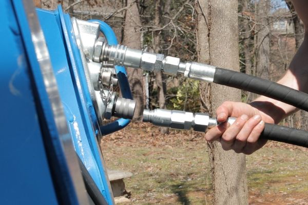
Apply the wrench only to the hex or machined wrench flats intended for assembly.
Do not clamp the wrench onto:
- The locking sleeve
- The coupling nose
- The valve face
- The hose connection area
- A thin-wall body section
Clamping the wrong area can distort the coupling and create a leak that is difficult to diagnose.
If the QD is being installed into a manifold or adapter, use a backup wrench where required. This prevents the coupling from transmitting installation torque into the hose, tube, manifold, or adjacent component.
Calibrate the torque tool
For repeated or production installation:
- Use a calibrated torque wrench.
- Confirm the calibration status before use.
- Verify the wrench on a suitable torque tester.
- Record the tool identification.
- Record the operator and date.
- Perform a first-piece or sample verification before batch assembly.
A torque value written on a work instruction is not enough if the tool is worn, out of calibration, or being used incorrectly.
Step 4: Install and Protect the O-Ring
The O-ring is often the smallest component in the assembly, but it has a major influence on leak performance.
Inspect the O-ring
Before installation, check that the O-ring has:
- The correct material
- The correct cross-section
- The correct inside diameter
- No cuts
- No nicks
- No flat spots
- No twisting
- No cracks
- No contamination
- No permanent deformation
Do not assume that an O-ring is acceptable because it looks clean in the package. Verify the part number and material where the application is safety-critical or chemically demanding.
Use compatible lubrication
Many O-rings should be lightly lubricated before installation, but the lubricant must be compatible with both the O-ring material and the system fluid.
Depending on the application, the manufacturer may specify:
- A compatible assembly grease
- A thin film of system fluid
- A special silicone-based lubricant
- A specific coolant-compatible lubricant
- No lubricant at all
The correct method must come from the coupling manufacturer or project specification.
Avoid twisting and cutting
During installation:
- Clean the groove and mating surface.
- Place the O-ring into the groove without twisting it.
- Apply a thin and even film of compatible lubricant.
- Insert the mating component slowly.
- Avoid pushing the component in at an angle.
- Stop if abnormal resistance is felt.
- Inspect the O-ring if the connection must be removed and reassembled.
Do not force the connection with a hammer or use a sharp tool to push the O-ring into position. A damaged O-ring may not leak immediately; it may leak only after pressure, temperature, or vibration changes.
Do not reuse a damaged or disturbed seal
Whether an O-ring can be reused depends on the manufacturer and the specific design. As a conservative assembly rule, replace an O-ring after it has been removed from a critical connection, especially if:
- It has been compressed for a long time.
- It has been exposed to high temperature.
- It has been exposed to chemicals.
- It has visible marks.
- It has been stretched during removal.
- The coupling has already experienced a leak.
- The connection is located near sensitive electronics.
Step 5: Control Alignment Before Connecting the QD Halves
Alignment is one of the most important factors in quick disconnect installation.
A QD coupling is designed to connect along a controlled path. If the male and female halves are forced together while misaligned, the result may be:
- O-ring shaving
- Uneven seal compression
- Excessive insertion force
- Valve damage
- Coupling body distortion
- Incomplete engagement
- Leakage under pressure
- Premature wear
Three types of misalignment
Axial misalignment
The two coupling halves are not at the same insertion depth or mounting height.
Possible causes include:
- Incorrect bracket height
- Unequal panel thickness
- Manufacturing stack-up
- A hose pulling one side of the assembly
- A manifold mounted too far forward or backward
The result may be incomplete engagement or insufficient seal compression.
Radial or lateral misalignment
The centerlines of the two coupling halves do not coincide.
Possible causes include:
- Incorrect hole location
- Poor fixture design
- Thermal movement
- Manufacturing tolerance accumulation
- A rigid pipe pushing the QD sideways
Radial misalignment may increase insertion force and cause the O-ring to scrape against the mating surface.
Angular misalignment
The two halves approach each other at an angle.
Possible causes include:
- A tilted flange
- Uneven fastener tightening
- Structural deformation
- Improper support
- Side load from a hose
Angular misalignment can produce one-sided O-ring compression and localized leakage.
Blind-mate QD installation
Blind-mate couplings are common in liquid cooling racks, manifolds, server trays, and modular equipment. The operator may not be able to see the coupling faces during connection.
This means that the equipment must provide the alignment.
Useful design features include:
- Guide sleeves
- Tapered lead-in surfaces
- Floating mounts
- Locating pins
- Captive mounting hardware
- Positive latching
- Mechanical hard stops
- Visual confirmation windows
- External support brackets
- Controlled tray travel
Step 6: Complete the Connection Without Forcing It
After alignment has been established:
- Confirm that both coupling halves are clean.
- Remove protective caps.
- Check that the locking mechanism is in the ready position.
- Bring the two halves together along the intended axis.
- Apply steady and controlled insertion force.
- Confirm the coupling reaches its specified engagement position.
- Check the sleeve, balls, latch, or retaining mechanism.
- Perform a visual or tactile confirmation.
- Secure the hose or pipe so it does not pull on the QD.
A positive click can indicate that a locking mechanism has engaged, but sound alone is not always sufficient. The equipment should also provide a clear position indicator or a defined mechanical stop.
Do not continue pushing if the coupling requires abnormal force. Excessive force often means that the halves are misaligned, the O-ring is damaged, the locking sleeve is not correctly positioned, or the coupling series is incorrect.
Step 7: Prevent Side Load and Hose Movement
A correctly connected QD can still leak if the surrounding hose or pipe creates continuous mechanical stress.
The coupling should not be used as a structural support for:
- A heavy hose
- A rigid pipe
- A suspended component
- A moving machine part
- A cable bundle
- A tray that is not properly guided
Use suitable supports, clamps, and strain-relief features. The support should stabilize the assembly without crushing the hose or transferring excessive load into the QD body.
Step 8: Perform a Controlled First Fluid Test
The first fluid test should be treated as a commissioning procedure, not a quick visual check.
Before introducing fluid:
- Confirm that all QDs are fully engaged.
- Confirm that the correct coupling series is installed.
- Confirm that torque records are complete.
- Confirm that the O-rings are approved.
- Confirm that the system is clean.
- Confirm that pressure sensors are working.
- Confirm that the leak detection system is active.
- Confirm that the emergency shutdown process is available.
- Protect nearby electrical equipment where necessary.
Use a gradual pressure increase
Do not immediately apply full operating pressure to a newly assembled system.
A controlled sequence may include:
- Fill or pressurize the system at a low level.
- Inspect each QD and connection point.
- Hold the pressure for the project-defined time.
- Increase pressure to the next step.
- Repeat the inspection.
- Continue until the required test pressure is reached.
- Record pressure, temperature, and time.
- Depressurize safely after the test.
The exact pressure steps and hold times must be defined by the system designer, equipment manufacturer, and applicable safety requirements.
Check for more than visible liquid
A leak may appear as:
- A visible drip
- A wet film
- A growing stain
- A pressure drop
- A coolant odor
- A change in fluid level
- Repeated air bubbles
- A leak detector alarm
- A temperature or flow abnormality
First Fluid Test Checklist
A practical commissioning checklist should include the following items.
| Check | Method | Acceptance Requirement |
| Part number verification | Compare installed parts with the bill of materials | Correct QD series and size |
| Coupling engagement | Visual and tactile inspection | Fully seated and locked |
| Torque verification | Review records or recheck selected connections | Meets approved specification |
| O-ring inspection | Sample inspection or replacement check | Correct, clean, undamaged |
| Alignment inspection | Fixture, gauge, or visual method | Within manufacturer tolerance |
| Low-pressure test | Gradual pressurization | No visible leakage |
| Pressure hold | Hold at defined test level | No unacceptable pressure loss |
| Bubble inspection | Observe transparent sections or vent points | No continuous abnormal bubbles |
| Alarm test | Simulate leak signal | Alarm responds correctly |
| Data recording | Log pressure, temperature, and flow | Complete commissioning record |
| Post-test inspection | Inspect after depressurization | No wetness, deformation, or movement |
Common Production Mistakes
“Tighten it a little more”
If a connection leaks, adding torque may make the problem worse. The real cause may be a cut O-ring, damaged port, cross-threaded connection, or misalignment.
The safer procedure is:
- Stop the system.
- Release pressure.
- Remove the connection safely.
- Inspect the seal and mating surfaces.
- Confirm the part number.
- Reassemble with the approved method.
- Retest.
Relying on operator feel
Experienced operators are valuable, but hand feel is not a substitute for a controlled process. Torque tools, alignment fixtures, visual indicators, and records reduce variation between operators and shifts.
Connecting under pressure
Never connect or disconnect a QD under pressure unless the coupling is specifically designed and approved for that operation.
Trapped pressure can create a dangerous release of energy and may prevent the valves from engaging correctly.
Losing torque records during shift changes
The next operator should know:
- Which parts have been assembled
- Which torque tool was used
- Which connections were tested
- Which items remain incomplete
- Who performed the inspection
- What abnormalities were found
A signed record is part of the assembly, especially for critical liquid cooling or hydraulic equipment.
Using incompatible sealants or lubricants
A lubricant that works with one O-ring material may damage another. A thread sealant that works on a tapered thread may interfere with an O-ring face seal.
Material compatibility must be confirmed before use.
Final Takeaway
Installing a quick disconnect coupling without leaks is not a matter of simply pushing the halves together or tightening the threaded end until it feels secure.
For blind-mate liquid cooling applications, the structure around the QD is just as important as the coupling itself. Guide sleeves, locating pins, floating mounts, latches, and visual confirmation features help keep the connection inside its designed tolerance range.