Repeated crimps that develop uneven flats, unusual marks, asymmetry, or changing measurements indicate a process problem, but they do not prove the dies are worn. Worn crimp dies can affect one-piece hose assemblies by changing how compression is distributed around the ferrule, yet incorrect setup, debris, poor die seating, measurement error, hose variation, or damaged components can create similar symptoms. A sound investigation starts by containing the affected work, documenting the pattern, and testing competing causes against evidence. It does not keep suspect dies in use or assign a wear limit without an approved tooling procedure.
Begin with the Pattern, Not a Presumed Cause
The first task is to describe what changed. A conclusion such as “the dies are worn” is premature until the team knows when the variation began, which configurations are affected, and whether the evidence follows the tooling.
Describe the observable symptoms
Record actual measurements, measurement positions, ferrule appearance, die marks, and any asymmetry around the circumference. Note whether the condition appears on one segment, repeats at the same angular position, changes between cycles, or affects only one hose-and-fitting combination. Photograph parts under consistent lighting when the quality system permits, while preserving their identity and sequence.
Do not classify every out-of-round result as die wear. A shifted hose, cocked fitting, incorrect die set, loose tooling, contamination, instrument error, or ferrule variation may produce a profile that resembles worn tooling. The observation should remain neutral: for example, “one flat is wider and readings vary by position,” not “die segment is worn.”
Establish the last known accepted state
Identify the last accepted tooling check, first-piece approval, or verified production result. Record the machine, die set, setup program, hose and fitting codes, instruction revision, operator or station, and measurement device. This reference helps define the trace-back window without inventing a fixed number of cycles.
If the symptom involves an installed hydraulic assembly, stop the equipment, isolate the system, release pressure and stored energy, secure raised loads, and follow lockout and manufacturer instructions before inspection. Never touch a suspected high-pressure leak or use a questionable assembly for diagnosis.
Contain Tooling, Product, and Records
Containment prevents uncertain tooling from creating more uncertain product. It also preserves evidence before cleaning, adjustment, or replacement changes the condition being investigated.
Stop and identify the scope
Take the suspect die set and related tooling out of service under the shop’s hold procedure. Label the machine setup so another operator cannot resume it. Segregate the current first piece, in-process assemblies, and finished assemblies produced since the last accepted check or other justified trace point.
The trace-back scope should consider:
- the tooling identity and any segment replacements;
- machine and setup records;
- hose, fitting, and ferrule lots;
- first-piece and periodic inspection results;
- measurement device history;
- maintenance, cleaning, or abnormal-event records;
- jobs run since the last accepted evidence.
Do not automatically scrap everything in the window, and do not release it merely because most pieces look normal. Place it on hold until a qualified review defines the applicable inspection, test, or disposition.
Preserve the as-found condition
Record die orientation, segment locations, seating, contamination, damage, and machine setup before disassembly or cleaning. Mark segment positions through an approved non-damaging method if the investigation needs to correlate a tool location with a ferrule feature. Preserve programs, settings, and instruction revisions used for the affected work.
Cleaning may be necessary later, but immediate cleaning can erase evidence of trapped debris, corrosion product, or uneven seating. Capture the as-found state first, then follow the approved inspection process.
Separate Die Wear from Setup and Component Variation
Fault isolation compares plausible causes rather than making one favored cause fit every observation. Change one controlled factor at a time where the approved investigation procedure allows.
Check setup and identity
Verify the exact hose manufacturer, hose series, size, fitting code, and approved crimp instruction. Confirm the machine, die set, adapters, program, and revision against the traveler. Matching dash sizes do not prove hose-and-fitting compatibility, and an incorrect die can be installed even when its external shape resembles the expected set.
Review hose preparation, insertion position, and fitting alignment. If only one assembly family shows the problem, compare its preparation and component records before blaming tooling used successfully on other approved configurations. If every configuration on the same die position shows a similar angular symptom, tooling or seating becomes a stronger hypothesis, but still requires inspection.
Check normal and abnormal component variation
Compare hose and fitting identities, lots, and dimensional inspection records within the approved system. A changed hose outside diameter, ferrule condition, mixed fitting code, or damaged part can influence the finished profile. Do not invent allowable component ranges; use current drawings, incoming inspection criteria, and manufacturer data.
Ask whether the symptom tracks the die set, the machine, the component lot, the operator method, or the measurement device. Evidence that moves with one factor is more persuasive than a general association with repeated production.
Read Surface Evidence Without Overclaiming
Uneven flats, marks, and asymmetry can guide the investigation, but surface appearance is screening evidence. It cannot alone establish tooling wear or assembly acceptance.
Correlate marks with die positions
Compare repeated ferrule marks with the recorded orientation of die segments. A recurring feature at the same tooling position may indicate damage, contamination, or seating trouble in that area. A feature that rotates with the part or appears randomly may point toward loading, component, or measurement variation instead.
Look for localized scoring, burr transfer, inconsistent flat width, unexpected ridges, or incomplete closure patterns. Record whether the feature appears before or after cleaning and whether it is present on a known reference piece. Do not polish, grind, stone, or otherwise alter tooling unless an approved repair procedure and qualified authority permit it.
Distinguish cosmetic evidence from functional evidence
A visible mark is not automatically a reject, and a smooth-looking ferrule is not automatically acceptable. Evaluate the part against the controlled visual and dimensional criteria for the exact assembly. If the procedure requires further test or engineering review, appearance cannot waive that requirement.
Pressure suitability and performance depend on the complete hose assembly, including the hose, fitting, preparation, crimp process, and application conditions. Tooling appearance cannot establish those properties.
Inspect Die Seating, Cleanliness, and Condition
Die condition includes more than gradual wear. Incorrect seating, foreign material, corrosion, segment damage, and mismatched pieces can all change the compression profile.
Examine the complete tool stack
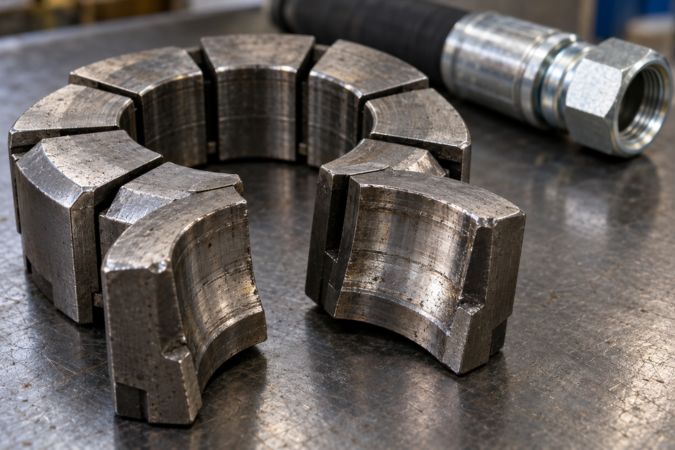
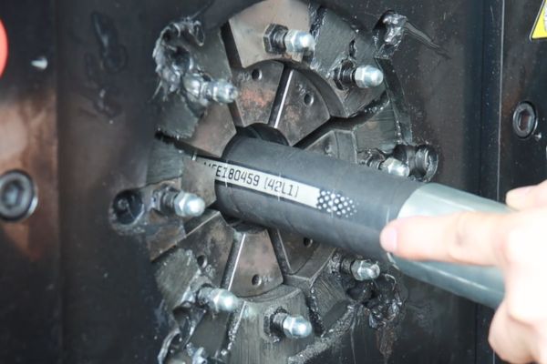
Inspect the die segments, master die or bowl, adapters, retainers, and seating surfaces identified by the equipment procedure. Confirm that all segments belong to the same controlled set and that identification is legible. Look for chips, cracks, damaged edges, fretting, unusual contact areas, or segment movement that differs from the expected condition.
Clean only after the as-found record is complete, using the approved method. Reinspect the seating faces and working surfaces under suitable lighting. If a condition cannot be judged reliably, keep the tooling quarantined for qualified assessment rather than returning it to service based on a quick visual check.
Avoid invented wear thresholds
There is no responsible universal statement that a die is acceptable for a certain number of cycles or until a particular visible amount of wear occurs. Allowable condition and replacement criteria depend on the equipment maker, tooling design, controlled maintenance program, and process capability evidence.
Do not continue using suspect dies because an average measurement remains within a target. Localized compression can be uneven even when one calculated value appears acceptable, and the approved method may require multiple positions or other profile checks.
Repeat Measurements with a Controlled Method
Measurement repeatability must be established before numerical variation is attributed to tooling. The same part measured differently can create a false trend.
Verify the instrument and technique
Confirm the device identity, calibration status, resolution, cleanliness, and zero or reference check required by the procedure. Use the specified measurement locations and avoid seams, flash, raised marks, or other excluded features. Hold the instrument consistently without excessive force or angular misalignment.
Repeat the measurement as the approved instruction requires, recording individual readings rather than only an average. Have a second qualified person repeat the method when the quality procedure calls for verification. If results differ materially by operator or technique, resolve the measurement system before adjusting the crimper or condemning the dies.
Compare evidence across controlled samples
Where the approved investigation permits, compare the affected result with a known accepted reference, a verified die set, or another controlled machine while changing only one factor. Do not create production assemblies from an unapproved combination merely for comparison. Any trial pieces remain identified and segregated until their disposition is recorded.
A symptom that follows the suspect die set under controlled conditions strengthens the tooling hypothesis. A symptom that remains with the machine, component lot, or measurement device points elsewhere. The goal is causal evidence, not a convenient explanation.
Decide on Tooling Inspection or Replacement
Only a qualified assessment under the approved procedure should release, repair, or replace suspect tooling. Operators should not create their own wear limits or repair methods.
Use cause–evidence–decision logic
| Possible cause | Evidence to seek | Controlled decision |
| Wear or die damage | Repeatable location, inspected surface change, symptom follows tooling | Quarantine; qualified repair or replacement review |
| Dirty or poor seating | As-found debris or incomplete contact; result changes after approved cleaning and setup | Correct setup; repeat first-piece release |
| Wrong setup or die identity | Mismatch with traveler, program, or instruction | Restore approved setup; assess affected product |
| Measurement error | Instrument or method problem; poor repeatability | Correct measurement system; re-evaluate held product |
| Hose or fitting variation | Symptom tracks identified component lot or preparation | Contain lot; inspect against controlled data |
The table does not define acceptance limits. It connects each hypothesis to the evidence needed before a disposition is made.
Requalify the setup after action
After approved cleaning, repair, replacement, or setup correction, repeat the required machine checks and first-piece inspection. Record the new tooling identity or maintenance action, actual measurements, visual results, and approval. Do not assume a replacement die recreates the prior setup without verification.
Trace and Disposition Affected Assemblies
Correcting the tool does not resolve product already made. The team must determine which assemblies could be affected and what evidence is needed for release, additional evaluation, or rejection.
Define the review window
Use the last accepted check, maintenance record, tooling event, measurement trend, and production traceability to establish a technically justified window. Include jobs that used the suspect configuration, not unrelated work merely because it occurred on the same day. Expand the scope when evidence shows the condition may have begun earlier.
For each held group, record hose and fitting identities, lots, production time or sequence, machine, tooling, program, inspection results, and the relationship to the observed fault. Do not rely on memory or reconstruct identifiers after labels have been lost.
Authorize disposition
Release, additional inspection, test, rework, or scrap decisions must follow the approved quality system and qualified technical review. Do not re-crimp or reuse a questionable hose assembly without a validated procedure. A passed sample does not automatically approve every unit in a variable population.
Conclusion
Inconsistent crimp profiles require containment and disciplined fault isolation, not an immediate claim that the dies are worn. Record the pattern, preserve the as-found setup, and trace product back to the last accepted evidence. Then compare tooling condition and seating with setup identity, hose and fitting variation, insertion, machine status, and measurement repeatability. Surface marks and asymmetry can focus the investigation, but a qualified assessment must determine whether a die is worn, damaged, repairable, or suitable for return to service. After any approved action, repeat first-piece release and document the result. This evidence-based approach to worn crimp dies in one-piece hose assemblies protects both the current process and assemblies already produced.
Frequently Asked Questions
Does an out-of-round crimp always mean the dies are worn?
No, setup, seating, contamination, component variation, loading, and measurement technique can create similar results. Isolate the cause with controlled evidence before replacing tooling.
Can dies stay in service if the average diameter is acceptable?
Not automatically, because an average may hide local variation or an abnormal profile. Follow the approved multi-position measurement and tooling-condition criteria, and quarantine suspect dies for assessment.
Should a damaged die segment be replaced by itself?
Only if the tooling manufacturer and approved maintenance procedure permit that action. Some sets require controlled matching or complete-set replacement, so do not improvise the repair.
How far back should affected assemblies be traced?
Use the last accepted check and available production, maintenance, and measurement evidence to define the window. There is no universal number of cycles that fits every process.
Can held assemblies be re-crimped after the dies are replaced?
Only under an approved, validated disposition that specifically permits re-crimping for that assembly. Otherwise, keep them segregated for qualified review, testing, rejection, or other authorized action.