One close-up is usually not enough to investigate a damaged hydraulic fitting. It may show a scratch but hide which end, part number, batch, thread, sealing face, hose, crimp, installation, or package it belongs to. To photograph one-piece fitting damage effectively, capture a sequence: overall identity, multiple views, the failure area, adjacent interfaces, scale, and relevant context. Preserve the original condition before cleaning whenever it is safe. Photos support technical review, but they do not prove root cause or replace measurements, material evidence, crimp data, or physical inspection. Above all, never approach a pressurized leak for a better image.
Make the Area Safe Before Capturing Evidence
Photography is secondary to stored-energy control. A pressurized hydraulic leak can penetrate skin, move a component, or release hot fluid even when it appears small.
Isolate and depressurize first
Stop the equipment, isolate the hydraulic system, release pressure and stored energy, secure suspended loads, and apply lockout procedures when required. Follow the equipment, hose, and fitting manufacturers’ instructions. Confirm that the component is safe to approach before taking close photographs or removing it.
Do not use a hand, cloth, paper, camera, or phone to search for a pinhole leak. Do not ask someone to stand near a live line as a scale reference. If an operating-condition record is necessary, use approved remote monitoring or site procedures without placing a person in the hazard zone.

Preserve the scene without creating a second failure
Once safe, record the installed state before loosening parts. Photograph routing, supports, bend location, clearance, contact points, orientation, nearby contamination, and visible fluid paths. Do not move the hose into a “better” pose until those views exist.
After removal, protect open ports from contamination and retain mating components when relevant. Avoid scraping threads, wiping sealing faces, cutting the hose, or discarding seals and packaging before the investigation owner decides what evidence is needed. If immediate cleaning is required for safety, document the condition and the cleaning step.
Capture a Minimum Four-Part Photo Set
A useful set moves from context to detail. Each image should answer one question while remaining linked to the same case and component.
Overview and identification establish what was examined
Take an overall image of the complete fitting or hose assembly from more than one side. Include both connection and hose ends, bends, swivel nuts, ferrule, and enough background to orient the part. Then capture markings, part number, hose layline, batch or lot, label, and any tag separately at readable focus.
Do not rely on a handwritten caption placed over a feature. Use a case card beside the part showing a non-sensitive case ID and image sequence, while keeping the original files unchanged. If no marking exists, photograph that absence and record how the sample was linked to the shipment or machine.
Failure-area and context views explain location
First photograph the damage with enough surrounding geometry to show where it is. Then move closer for surface detail. Take perpendicular and oblique angles because dents, raised burrs, cracks, coating loss, and scratches reflect light differently.
Context may include the installed port, adapter, clamp, guard, moving structure, abrasion point, packaging, adjacent parts, or fluid path. A removed close-up cannot show side load, interference, a tight bend, or carton damage. Preserve both levels of evidence.
| Photo | Framing | What it can show |
| Installation overview | Equipment area and full hose route from a safe position | Routing, supports, bend location, contact, orientation |
| Component overview | Entire fitting or assembly from several sides | Configuration, ends, ferrule, swivel, relative damage location |
| Identification | Marking, label, hose layline, batch, case card | Product and traceability clues |
| Damage close-up | Defect plus surrounding feature, then tighter detail | Scratch, dent, burr, fracture, coating loss, contamination |
| Scale view | Scale in the same plane without touching damage | Approximate feature size for triage, not certified measurement |
| Mating and packaging context | Port, adapter, seal, cap, inner pack, carton | Related damage, contamination, and transit evidence |
Control Lighting, Focus, Angle, and Scale
Technical photos should reveal surface shape and location without hiding uncertainty. Camera quality matters less than stable focus, appropriate light, and a repeatable sequence.
Use light to show form, not to dramatize it
Clean the camera lens and use diffuse light for general views. Add low-angle light to reveal raised material, dents, thread deformation, or coating texture. Avoid a flash reflection that turns a metal seat into a white patch. Take a second view when glare cannot be eliminated.
Stabilize the camera and tap or set focus on the feature. Fill enough of the frame to show detail, but keep an orientation image. Digital zoom can enlarge blur without adding information. Retain full-resolution originals and avoid filters, sharpening, annotation, or compression that changes edges.
Use scale as a reference, not a measurement report
Place a clean ruler, gauge card, or approved scale in the same plane as the damage. Do not rest it on a sealing face, thread, loose fracture, or contaminated fluid. Photograph the scale markings sharply and keep one image without the scale in case it obscures the feature.
Perspective and lens distortion make photo measurements approximate. If a dimension affects acceptance, use a calibrated instrument and record the method separately. A coin, finger, or unknown fastener is a poor scale because size varies and it can contaminate the evidence.
Photograph Threads and Sealing Surfaces Deliberately
Threads and sealing interfaces need their own sequence because a general component photo rarely shows lead damage, seat scratches, O-ring grooves, or contact paths clearly.
Rotate through the complete thread circumference
Capture the thread start, several side views, runout, and any local damage. Rotate the part in controlled increments while keeping orientation clear. Use oblique light to show flattened crests, crossed starts, dents, burrs, galling, coating buildup, or embedded debris.
For internal threads, illuminate the bore without inserting the light or camera against the feature. A mirror or suitable optical scope may be needed. Record areas that cannot be seen. Photos cannot prove thread form, pitch, taper, or class; use the specified gauges and measurements for those decisions.
Protect flare seats, faces, and grooves
Photograph the sealing surface before wiping it. Take a centered view to show the full seat or face and an angled view to reveal scratches, dents, chatter, residue, or corrosion. For an O-ring groove, capture the entry edge, groove, seal condition, and mating face separately.
Do not mark a scratch with a metal pointer or insert a gauge just for the photo. A paper or digital annotation can identify the area on a duplicate image while the original stays unaltered. Seat geometry and roughness require controlled inspection; an image only documents visible condition.
Record Ferrule, Hose, and Crimp-Related Damage
The fitting body is only one part of a hose-end investigation. Capture how the ferrule, stem, hose cover, reinforcement, and installed route relate to the reported condition.
Photograph the assembly before cutting it apart
Take the complete hose end from several angles. Show ferrule position, any gap or movement, hose insertion reference if externally visible, cover bulging, cuts, wire exposure, twist, kink, bend immediately behind the ferrule, and abrasion. Include the hose layline and opposite end when practical.
Do not pull, twist, or recrimp the assembly to demonstrate looseness. Such handling can enlarge damage and destroy the original relationship. If destructive examination is approved later, document each stage and keep removed pieces identified.
Link photos to assembly evidence
Record hose manufacturer, series, dash size, fitting part or series, crimp specification source, assembly equipment and die information when available, measured crimp data, date, and assembler or station identity under the quality procedure. Do not infer compatibility from a matching dash size or approximate diameter.
Photos may show deformation or pull-off, but they cannot identify the cause alone. Incorrect component matching, insertion, crimp, routing, pressure impulses, heat, fluid, external damage, and installation load may produce overlapping appearances. Preserve evidence for the broader review.
Include Installation and Packaging Context
Context explains forces and handling that a clean bench photograph removes. Capture it when damage may relate to movement, contact, transport, storage, or contamination.
Show the installed environment
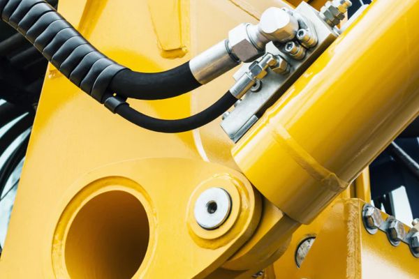
Photograph the port and adapter, hose route, clamps, guards, articulation points, heat sources, sharp edges, neighboring components, and available clearance after safe isolation. Use wide, medium, and close views. Note the machine position because routing can change through its motion range.
Avoid including people, serial numbers, customer names, addresses, or unrelated proprietary equipment unless necessary and authorized. A case image should contain enough technical context without exposing customer-sensitive information.
Preserve packaging evidence
Before unpacking further, photograph the outer carton on all sides, shipping label linked to the case, crushed or wet areas, punctures, tape, inner packs, separators, caps or plugs, loose parts, mixed labels, and where the damaged fitting sat. Do not rearrange the contents until an overview exists.
A damaged carton suggests a transport event but does not prove when the fitting damage occurred. An intact carton also does not clear the parts. Compare packaging, part-to-part contact, corrosion, missing caps, and batch evidence with receiving inspection.
Name, Link, and Preserve the Evidence Set
Good images lose value when files are renamed casually, separated from the case, or sent through a service that removes resolution and metadata.
Use a predictable sequence
Name files with a non-sensitive case ID, sample ID, view type, and sequence, for example CASE104-S2-thread-start-03. Keep a case index that links image numbers to part number, batch, shipment or equipment record, photographer, date, and a short factual description.
Retain original files in a controlled location. Work from copies for cropping, arrows, or callouts, and label edited copies. Do not overwrite originals. Record if the device clock was wrong or if compression occurred during transfer.
End with a capture checklist
- Confirm isolation, depressurization, stored-energy release, and safe access.
- Capture installation overview before moving or removing the assembly.
- Photograph the complete component, identification, and every side.
- Capture damage with orientation, close-up, multiple light angles, and safe scale.
- Document threads, sealing surfaces, ferrule, hose, and mating parts separately.
- Preserve residue and original damage before cleaning when safe.
- Photograph carton, inner packaging, labels, caps, and mixed-SKU evidence.
- Record inaccessible areas and measurements still required.
- Link originals to the case, sample, batch, and shipment without exposing private data.
- State clearly that photo interpretation is preliminary until physical evidence is reviewed.
Conclusion
Damage photography works as a sequence, not as a single dramatic close-up. Start with safety and the installed overview, then record product identity, full component geometry, the defect, adjacent threads or sealing surfaces, hose and ferrule condition, scale, and relevant packaging. Use controlled light, stable focus, and multiple angles while protecting the original evidence. Keep untouched files linked to the case, sample, batch, and shipment, and document anything the camera could not show. Photos narrow technical questions but cannot establish dimensions, compatibility, material, or root cause alone. That discipline gives reviewers useful facts without asking an image to prove more than it can. Before you photograph one-piece fitting damage, isolate the system, preserve context, and prepare a complete evidence set for measured inspection.
Frequently Asked Questions
What should be used as a scale reference in damage photos?
Use a clean ruler or approved gauge card placed in the same plane without touching the damage. Treat photo dimensions as approximate until a calibrated measurement confirms them.
Is video useful for a fitting complaint?
It can show orientation, movement, or the sequence around a safe inspection, but it should supplement focused still images. Never record close to an operating pressurized leak.
Should a dirty fitting be cleaned before photography?
Not before the original condition is documented when it is safe to preserve it. Afterward, use the approved cleaning method and capture a second set if inspection requires it.
Should damaged packaging be included in the photo set?
Yes. Record the unopened arrangement, labels, wet or crushed areas, inner protection, and part position because they may support a transit assessment without proving cause alone.
How should a pressurized leak be photographed?
Do not approach or search for it with a camera. Stop and isolate the equipment, release pressure and stored energy, secure loads, and inspect only after the system is confirmed safe.