Before a crimp cycle starts, ask one release question: is this machine configured for this exact hose-and-fitting combination under a current approved procedure? A reliable one-piece hydraulic fitting crimper setup links the identified hose, complete fitting code, machine, die set, program or adjustment method, tooling condition, and instruction revision. Entering the correct nominal crimp target is not enough when the wrong dies, stale program, uncertain calibration status, or mismatched components remain possible.
Use a Setup Release Gate Before Production
Treat setup as a controlled configuration that must be released, not as a collection of familiar operator actions. Production stays on hold until every required element points to the same approved assembly combination.
Define what is being released
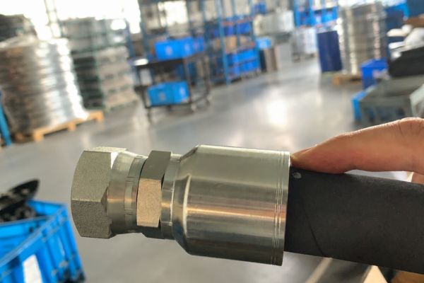
The release applies to a specific hose manufacturer, hose series, size, fitting code, and controlled crimp instruction on an identified machine with identified tooling. It does not approve every fitting in the same family or every hose with the same dash designation. A one-piece fitting keeps the stem and ferrule together, but that structure does not prove compatibility with an unlisted hose.
Write the assembly identity at the top of the traveler before checking machine values. Include the fitting orientation and connection when similar codes could be confused. If the instruction cannot be tied to that exact combination, stop and obtain controlled data rather than choosing a setup from memory or a neighboring catalog line.
Separate setup from compatibility
A machine can reproduce a programmed movement accurately while processing an unapproved hose-and-fitting pair. Setup verification therefore cannot replace the compatibility decision. Confirm first that current manufacturer data authorize the combination; then audit whether the crimper is configured to execute that approved process.
If an existing assembly must be removed for comparison, stop the equipment, isolate the hydraulic system, release pressure and stored energy, secure raised loads, and follow lockout and equipment instructions. Never open a pressurized connection or use a questionable assembly merely to see whether it operates.
Identify the Crimper and Die Set
Machine and tooling identity must be explicit because similar equipment may use different control logic, die nomenclature, correction factors, or maintenance status. Do not accept “the usual crimper” as a setup record.
Read permanent identifiers
Record the machine asset number, model or other controlled identity used by the shop. Confirm that the selected work instruction applies to that machine or approved machine group. If an adapter bowl, master die, die set, spacer, or other tooling element is part of the setup, identify each item according to the procedure.
Compare physical tooling marks with the traveler and setup document before installation. Tool location alone is not proof: a die returned to the wrong rack position can look familiar. Keep mixed or unreadable tooling in a hold area until its identity and condition are resolved.
Confirm correct installation
Clean and seat the tooling as the machine procedure requires. Check that mating surfaces are free of debris, that segments move freely and uniformly, and that retainers or positioning features are correctly engaged. A correct die set that is dirty, damaged, or incompletely seated can produce a different compression profile from the one assumed by the program.
Never invent die numbers, spacer combinations, force, pressure, or machine settings. Those details must come from the current manufacturer and process documentation for the exact equipment and assembly.
Verify Instructions, Program, and Revision
The workstation must use a current controlled crimp instruction. A valid target copied into an obsolete program does not make the setup current.
Link the source document to the program
Record the instruction number and revision, its effective date when controlled by the system, and the exact row or configuration used. Then open the machine program or setup record and compare its identity with that source. The program name should be specific enough to prevent an operator from choosing a similarly named hose or fitting family.
Check all controlled fields required by the procedure, not only the displayed target. Depending on the equipment, the approved setup may also govern tooling, machine mode, correction method, opening, sequence, or measurement workflow. This article cannot supply those values because they are machine- and combination-specific.
Prevent stale or informal data
Remove handwritten values and uncontrolled printouts from the active workstation unless the quality system explicitly controls them. A screenshot or old job traveler may document what was used previously, but it does not prove that the instruction remains approved after a hose, fitting, tooling, or program revision.
When the source and program disagree, stop. Do not select whichever value appears more conservative, average the two, or run a piece to decide empirically. Escalate the discrepancy to the document owner and preserve both references for investigation.
Check Tooling Condition and Calibration Status
Tool condition and machine status determine whether the configured process has a reliable physical basis. The setup gate must recognize expired, damaged, contaminated, or suspect equipment before a production piece is made.
Inspect the working surfaces
Examine dies and related tooling under suitable lighting. Look for contamination, corrosion, chips, burrs, cracks, unusual marks, uneven wear, damaged identification, or segment movement that differs from the approved condition. Do not create a universal wear threshold from visual judgment. If the tooling is questionable, remove it from service and obtain a qualified assessment under the shop procedure.
Confirm that cleaning did not leave foreign material on seating or working surfaces. Check the machine area for loose parts from the previous setup. A leftover spacer or incorrect component can invalidate an otherwise correct die selection.
Verify machine and measurement status
Review the machine’s calibration or verification status according to the controlled system. Confirm that required checks are current and that no unresolved alarm, maintenance hold, or out-of-tolerance history affects release. This article does not prescribe a calibration interval; use the equipment manufacturer’s requirements and the organization’s approved quality plan.
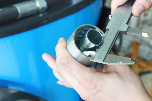
The measurement instrument used for the first piece also needs valid identification, suitable resolution, acceptable condition, and current calibration status. A machine setup cannot be released from a measurement taken with an inappropriate or uncontrolled tool.
Match Hose and Fitting IDs to the Traveler
Setup verification must use the components actually at the machine. Labels on a bin or work order do not replace physical identification when parts may have been mixed.
Confirm the hose
Read the hose layline or controlled identification and compare the manufacturer, series, size, and relevant lot information with the traveler. Verify the hose construction and preparation requirement from the current assembly instruction. Similar outside diameter or matching dash size cannot substitute for series identity.
Inspect the cut end and preparation for obvious damage, contamination, or deviation from the approved method. Confirm any required insertion-depth mark before the piece is loaded. Do not use the crimper to overcome difficult insertion or compensate for an unapproved preparation.
Confirm the fitting
Check the complete fitting code, series, size, orientation, end connection, and traceability information required by the process. For connection identification, distinguish thread form, diameter, pitch or TPI, straight or tapered thread, seat or sealing face, O-ring position, and male or female configuration. Do not identify the fitting from a photo or ferrule appearance alone.
Before release, the operator should be able to answer:
- Which controlled record approves this hose and fitting together?
- Which machine and tooling does that record require?
- Which program or setup revision is active?
- How was insertion confirmed before crimping?
- Which method and instrument will evaluate the first piece?
If any answer relies on memory or visual similarity, keep the job on hold.
Measure and Document the First Piece
The first piece tests the actual setup against the approved inspection method. It confirms a defined dimensional result and process execution; it does not by itself prove full compatibility or application performance.
Follow the approved measurement method
Allow the process and part to reach the condition required by the instruction before measurement. Use the specified locations, number of readings, instrument orientation, and method. Avoid measuring on an unsuitable feature, obvious flash, a mark, or another location excluded by the procedure. Record actual readings rather than only writing “pass.”
Inspect the crimp profile and component position for required visual conditions. Confirm that the hose did not shift, the ferrule and stem relationship is as specified, and orientation remains correct. If a result appears abnormal, separate possible measurement error from a true process result by checking the instrument, method, and reference before changing the machine.
Use a shop-floor signoff table
| Release item | Evidence to record | Release decision |
| Hose and fitting identity | Full codes, size, and traceability required by traveler | Match / Hold |
| Machine and tooling | Asset and tooling identifiers; condition acceptable | Match / Hold |
| Controlled instruction | Document and active revision | Current / Hold |
| Program or setup | Identifier matched to approved source | Match / Hold |
| Status controls | Machine and measurement device status | Valid / Hold |
| First piece | Actual measurements and required visual checks | Accept / Hold |
Signoff should identify the responsible operator or reviewer and the time or job reference required by the quality system. Keep the first piece segregated until release is complete.
Make Adjustments Only Through the Approved Procedure
An out-of-specification first piece is a signal to stop and investigate. Immediate adjustment can obscure whether the cause was component identity, insertion, measurement, tooling, program selection, or machine condition.
Investigate before changing values
Quarantine the first piece and prevent production from continuing. Reconfirm the hose, fitting, instruction, machine, dies, setup, insertion, and measurement method. Inspect for incorrect tooling seating, contamination, damage, or an unresolved machine status. Record the original configuration before any approved change so the evidence is not lost.
Do not re-crimp or salvage the failed assembly unless an approved procedure explicitly authorizes the disposition. Never adjust a setting by trial and error, borrow a value from another series, or continue producing while attempting to “dial in” the process.
Repeat release after an approved change
When a qualified authority approves a correction, document what changed and why. Return to the relevant setup checks, produce a new first piece as required, and repeat the complete measurement and signoff sequence. An adjustment does not inherit the earlier partial approval.
Apply the Final Go/No-Go Release
The final gate is binary: release only when all required evidence agrees. A single unresolved field keeps the setup in no-go status even if other checks look normal.
GO conditions
Release the setup when the exact hose and fitting combination is documented as compatible; machine, tooling, program, and instruction identities match; equipment and instruments have valid status; tooling condition is acceptable; preparation and insertion are confirmed; and the documented first piece meets the applicable criteria.
NO-GO conditions
Hold the setup for any identity mismatch, missing source, obsolete revision, suspect tooling, expired or uncertain status, unclear insertion, abnormal first piece, or undocumented adjustment. Label the condition, segregate affected components, and escalate to the responsible technical or quality authority. Production pressure does not turn incomplete evidence into approval.
Conclusion
A reliable crimper setup is a traceable match among the actual components, controlled process, equipment, tooling, and first-piece evidence. Begin by confirming that the exact hose-and-fitting pair is approved, then identify the machine and dies, verify the current instruction and active program, inspect tooling, and check machine and measurement status. Match the parts at the workstation to the traveler before crimping. Measure the first piece by the approved method and record actual results, remembering that one correct dimension does not prove compatibility or complete performance. If any result fails, preserve the original setup and investigate before an approved adjustment. Release a one-piece hydraulic fitting crimper setup only when every required field supports GO.
Frequently Asked Questions
Can I use the same crimper program for every fitting with the same dash size?
No, matching dash size does not prove that the program, tooling, or crimp instruction applies. Verify the exact hose series, fitting code, machine, and controlled setup record.
Does a correct first-piece diameter prove hose compatibility?
No, it confirms only the measured characteristic under the referenced method. Compatibility also depends on approved hose-and-fitting data, preparation, insertion, tooling, and any required performance evidence.
How often should a crimper be calibrated?
Use the equipment manufacturer’s requirements and the organization’s controlled quality plan. A universal interval cannot be assigned without considering the machine, process, usage, and applicable system.
What should happen when the die identification is unreadable?
Place the die in hold status and resolve its identity and condition through the approved tooling-control process. Do not select it by rack location, shape, or resemblance to another die.
Can an operator adjust the setup after a failed first piece?
Only through an approved procedure and authorized decision. First preserve the failed result, verify identity and measurement, investigate the setup, document the correction, and repeat required first-piece release.