
Hydraulic Hose Fitting Repair: Expert Tips for Quick Fixes
Hydraulic Hose Fitting Repair: Expert Tips for Quick Fixes Contact
Hydraulic Hose Fitting Repair: Expert Tips for Quick Fixes Contact
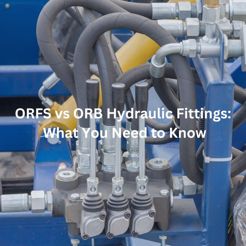
ORFS vs ORB Hydraulic Fittings: What You Need to Know
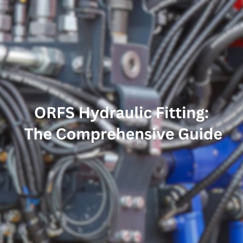
ORFS Hydraulic Fitting: The Comprehensive Guide Contact Us Introduction Hydraulic
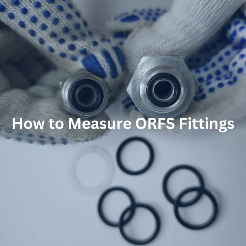
How to Measure ORFS Fittings Introduction ORFS (O-Ring Face Seal)
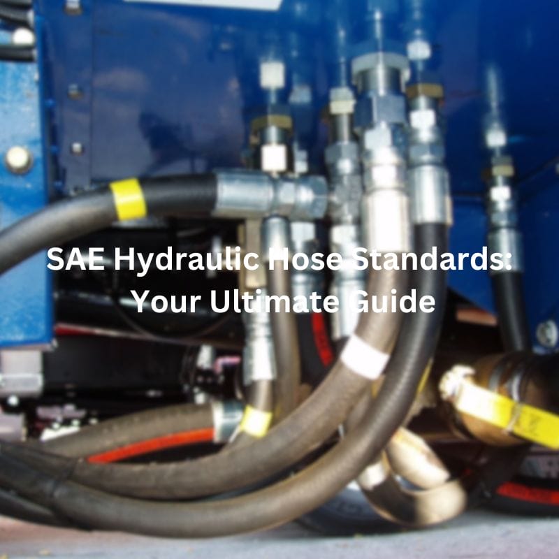
Understanding SAE Hydraulic Hose Standards: Your Ultimate Guide Contact Us
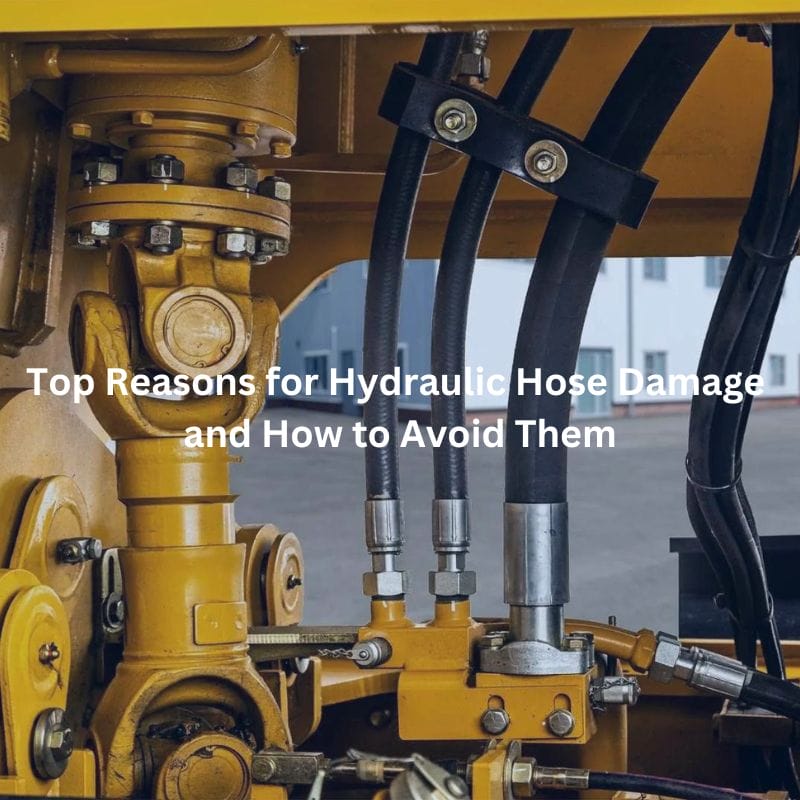
Top Reasons for Hydraulic Hose Damage and How to Avoid
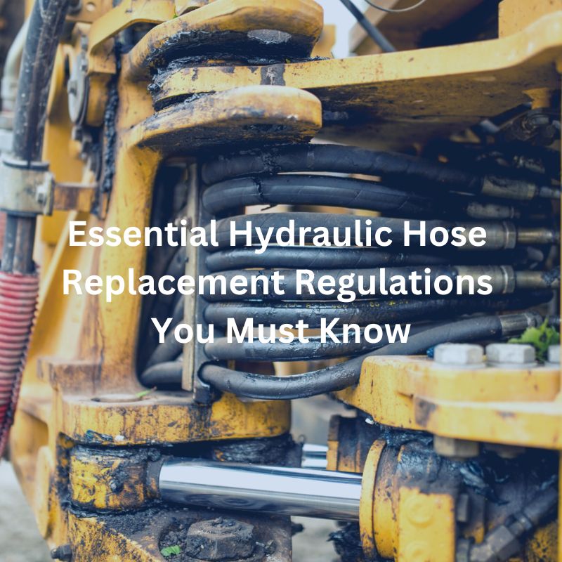
Hydraulic Hose Replacement Regulations You Must Know Contact Us Table

Hydraulic Hose Breakdown: Common Failures and Solutions Contact Us Table
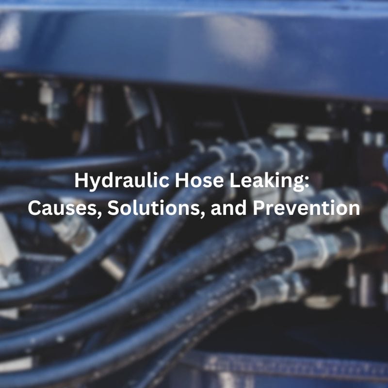
Hydraulic Hose Leaking: Causes, Solutions, and Prevention Contact Us Introduction
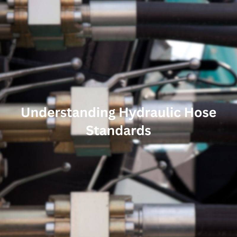
Understanding Hydraulic Hose Standards: Key Guidelines Contact Us Table of