Essential Hydraulic Hose Size Chart
Essential Hydraulic Hose Size Chart: Your Ultimate Guide Contact Us
Essential Hydraulic Hose Size Chart: Your Ultimate Guide Contact Us
How to Disconnect Hydraulic Hoses Contact Us Table of Contents

Hydraulic Hose Types: What You Need to Know Contact Us

Mastering Hydraulic Hose Repair: 5 Simple Steps to Follow Contact
Hydraulic Compression Fitting Pressure Ratings Explained Contact Us Table of
Top Tips for Repairing Leaking Hydraulic Fittings Easily Contact Us
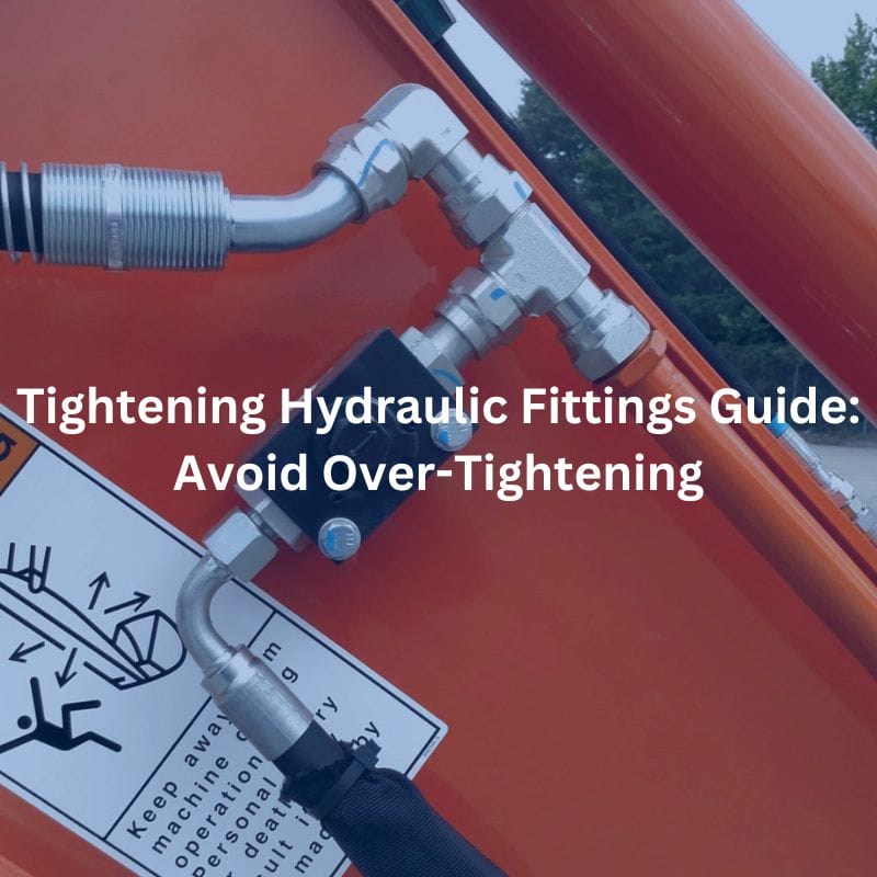
Tightening Hydraulic Fittings Guide: Avoid Over-Tightening Contact Us Table of
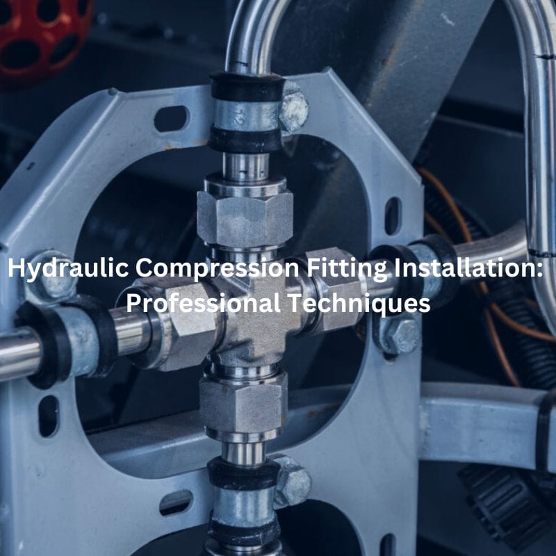
Hydraulic Compression Fitting Installation Tips Contact Us Table of Contents
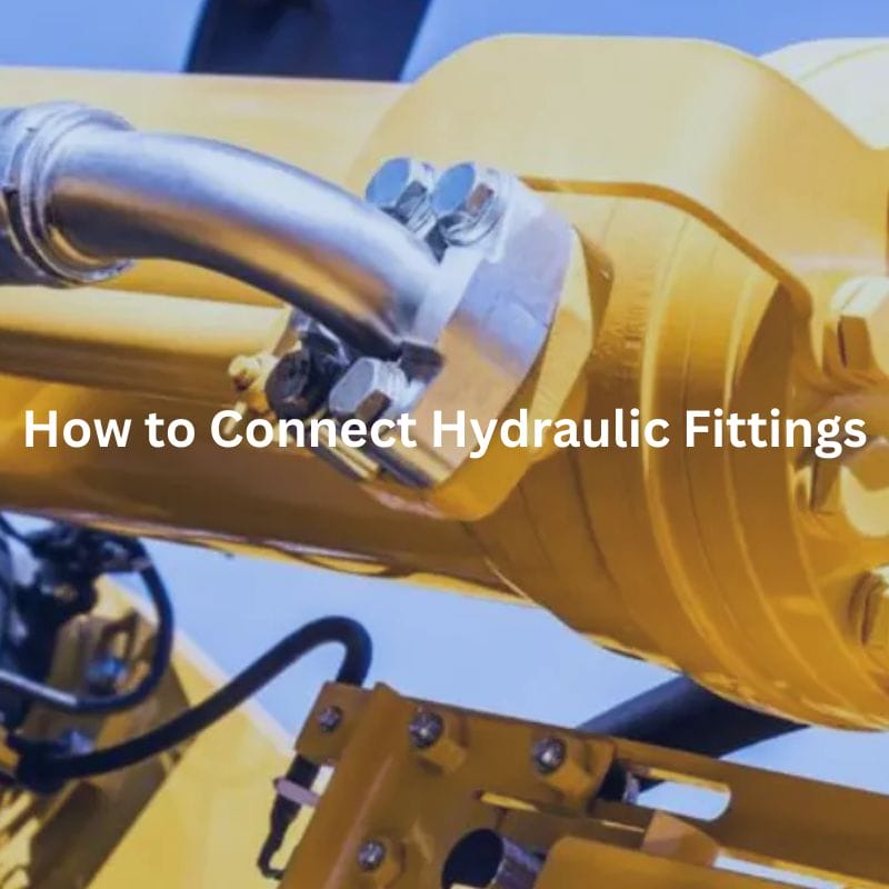
How to Connect Hydraulic Fittings Contact Us Table of Contents

Why More Engineers Are Choosing Swivel Hydraulic Fittings Contact Us