
How to Measure BSP Hydraulic Fittings
How to Measure BSP Hydraulic Fittings Contact Us Table of
How to Measure BSP Hydraulic Fittings Contact Us Table of

How to Measure Hydraulic Hose Fittings Table of Contents Introduction
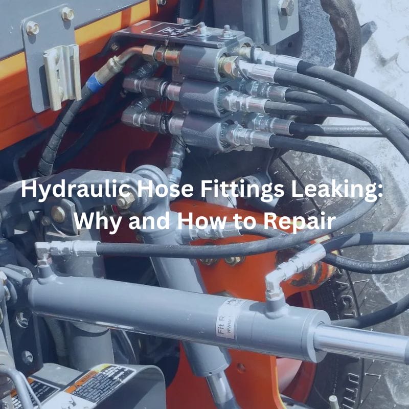
Hydraulic Hose Fittings Leaking: Why and How to Repair Contact
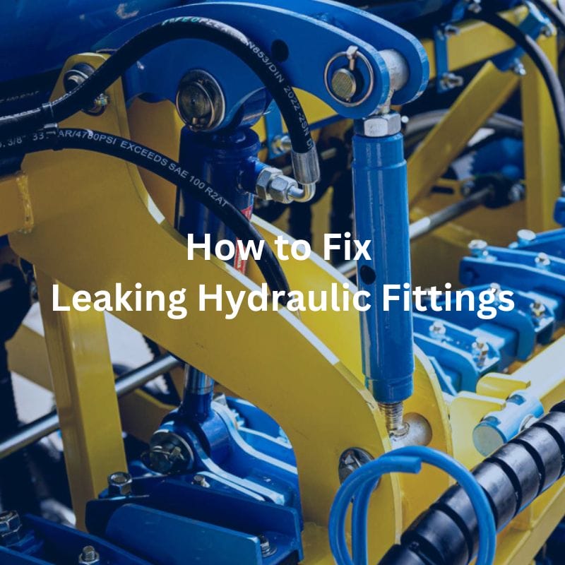
How to Fix Leaking Hydraulic Fittings Contact Us Table of
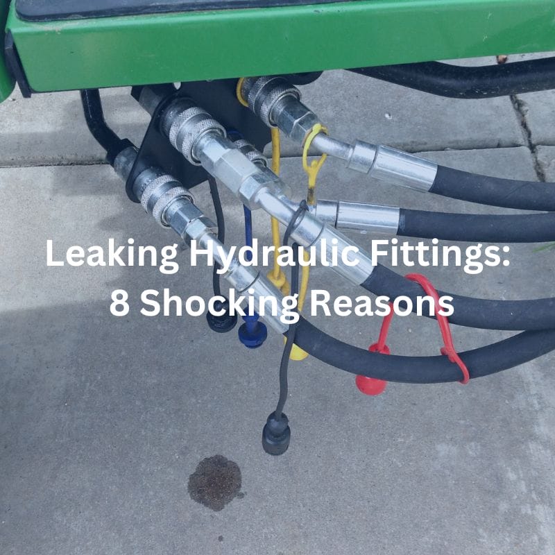
Leaking Hydraulic Fittings: 8 Shocking Reasons Contact Us Table of
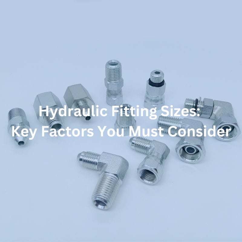
Hydraulic Fitting Sizes: Key Factors You Must Consider Contact Us

Hydraulic Hose Fitting Identification: Avoid Common Mistakes Table of Contents

Hydraulic Flange Fitting Size Chart: Your Ultimate Guide Contact Us
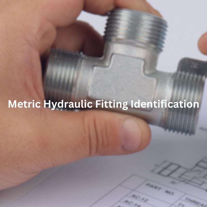
Metric Hydraulic Fitting Identification: Step-by-Step Guide Table of Contents Introduction
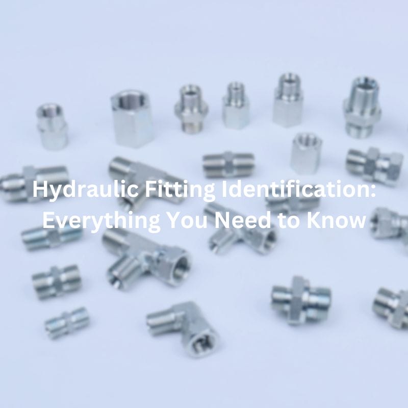
Hydraulic Fitting Identification: The Detail Guide Contact Us Table of