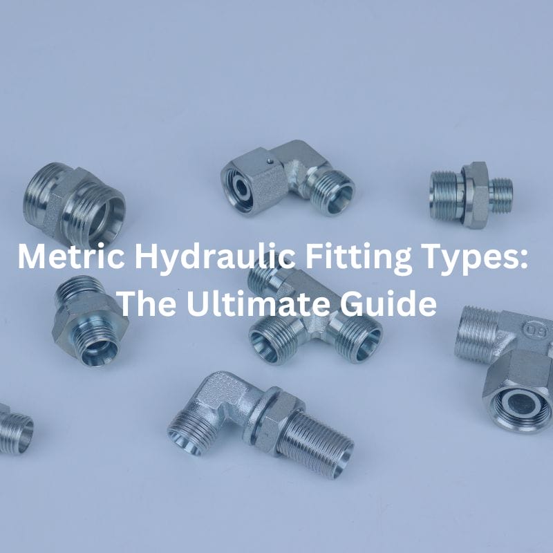
Metric Hydraulic Fitting Types: The Ultimate Guide
Metric Hydraulic Fitting Types: The Ultimate Guide Contact Us Table
Metric Hydraulic Fitting Types: The Ultimate Guide Contact Us Table
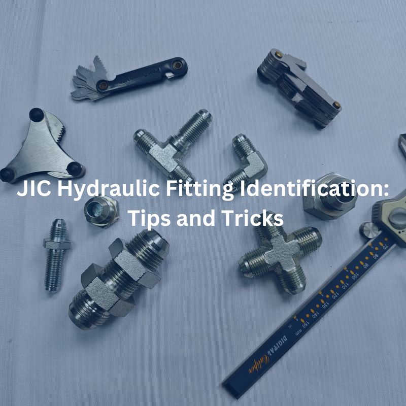
JIC Hydraulic Fitting Identification: Tips and Tricks Contact Us Table
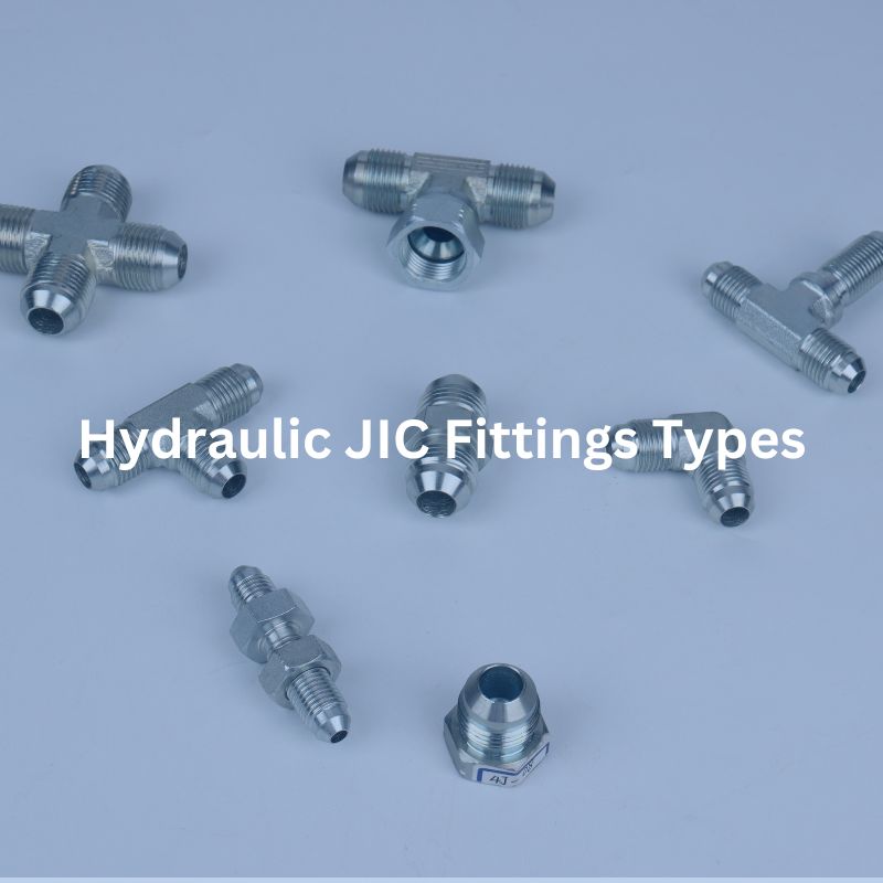
Hydraulic Fittings Types JIC: A Comprehensive Guide Contact Us Table

Types of Hydraulic Fittings with O Ring: A Detail Guide

BSPT vs BSPP Threads: Everything You Need to Know Table
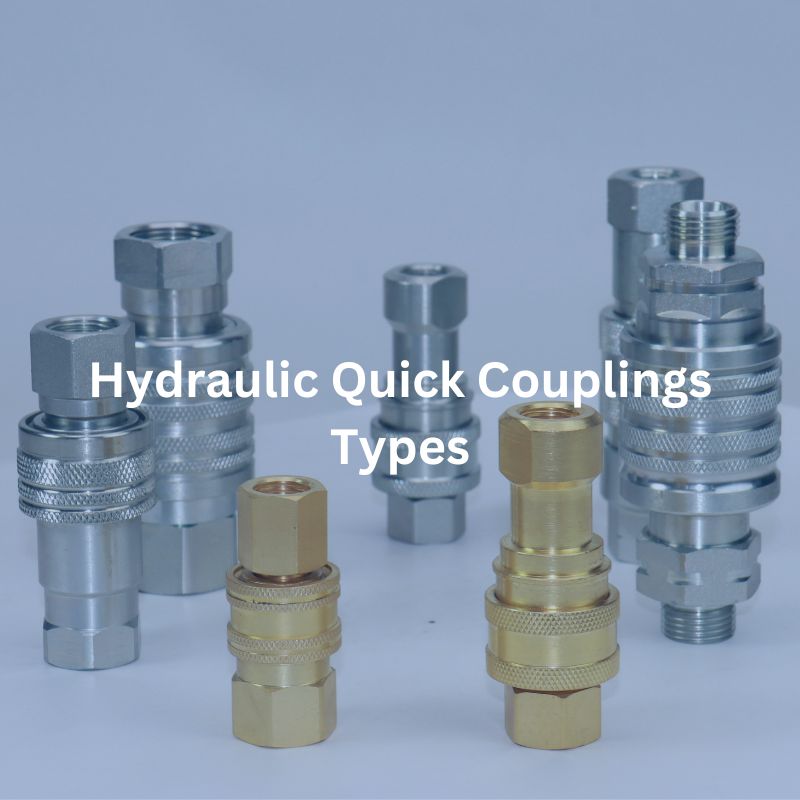
Hydraulic Quick Coupling Types: Comprehensive Guide Contact Us Table of
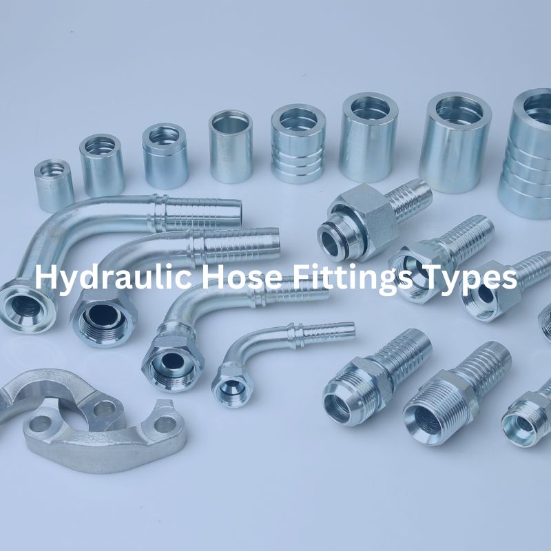
Hydraulic Hose Fitting Types: A Comprehensive Guide Contact Us Table
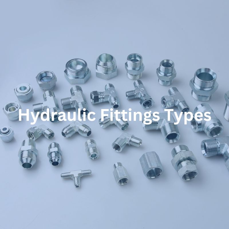
Hydraulic Fittings Types: The Ultimate Guide Contact Us Table of
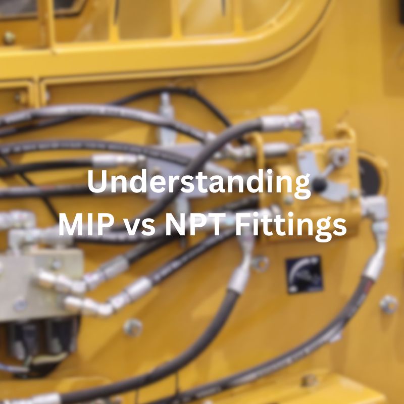
Understanding MIP vs NPT Fittings: Key Differences Introduction When it

What Are the Common Signs of Hydraulic Fitting Wear and