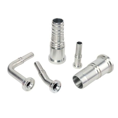
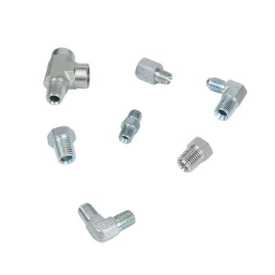
How to Identify Metric vs BSP Hydraulic Fittings

How to Identify Metric vs BSP Hydraulic Fittings

How to Identify Metric vs BSP Hydraulic Fittings

Table of Contents

Introduction

Using the wrong type can lead to leaks, system malfunctions, and even catastrophic failures, jeopardizing not only the machinery’s performance but also workplace safety. This article aims to demystify the process of distinguishing between Metric and BSP hydraulic fittings. By arming you with the necessary knowledge and tips, we endeavor to enhance your system’s efficiency and safety, ensuring that you choose the correct fitting type every time you encounter a hydraulic system. Understanding the subtleties of each fitting type not only optimizes operational performance but also minimizes risks associated with hydraulic systems.

Details on Metric Fittings

Metric hydraulic fittings are essential for the seamless operation of a variety of hydraulic systems, characterized by their specific dimensions, thread types, and sealing methods. Understanding these characteristics is crucial for ensuring compatibility and functionality within hydraulic systems.

Dimensions

When discussing the dimensions of Metric hydraulic fittings, it’s important to recognize that these components are meticulously standardized to ensure consistency across diverse applications. Metric fittings are measured using millimeters, which applies to both the outer diameter of the threads and the pitch, or the distance between each thread. This metric measurement system facilitates precise engineering and manufacturing across global industries.

Diameter of Threads

The diameter of Metric fittings can vary significantly depending on the application’s demand for strength and the space available for the fitting. Smaller diameters, such as M8 (8 millimeters), are typical in applications where space is limited and less fluid volume is required. These smaller fittings are common in light machinery or compact hydraulic systems within automotive contexts, where every millimeter of space must be efficiently utilized.

Pitch of Threads

The pitch in Metric fittings refers to the distance from the crest of one thread to the crest of the next. For example, an M8x1.0 fitting has a pitch of 1.0 millimeters, indicating very fine threading. Fine threads provide a higher degree of thread engagement and a better seal, which is crucial for systems operating under high pressure. On the other end of the spectrum, larger fittings like M48x2.0 have a pitch of 2.0 millimeters, which is suited for handling greater volumes and pressures, typical in industrial machinery such as construction equipment or heavy-duty manufacturing lines.

Common Sizes and Uses

The range from M8x1.0 to M48x2.0 covers a wide variety of applications. The smaller sizes (M8 to M16) are often used in precision applications such as hydraulic braking systems or fuel injection systems where tight seals and small clearances are paramount. Mid-range sizes (M18 to M30) are frequently found in commercial vehicles and agricultural equipment, balancing robustness and space efficiency. The largest sizes (M32 to M48 and beyond) are typically reserved for heavy industrial applications where large volumes of fluid must be moved reliably, such as in hydraulic presses or mining machinery.

Types of Metric Threads

Parallel (Straight) Threads

Description: As the standard thread type for Metric fittings, parallel threads maintain a consistent diameter across the entire length of the thread. This uniformity means that the threads do not taper towards the end, which is typical in some other thread types.

60-Degree Thread Angle: Metric threads are characterized by a 60-degree angle between the thread flanks. This angle is optimal for balancing force distribution across the thread faces, which is crucial when the fittings are subjected to high pressures.

Sealing Mechanism: Parallel threads themselves do not generally provide a seal but are used in conjunction with either O-rings placed in the mating face (face seal) or by compression of a soft sealing material as in a bonded seal. This arrangement is critical for preventing leaks and is especially effective in high-pressure systems.

Tapered Threads

Description: While less common in Metric system fittings and more frequently found in the NPT (National Pipe Taper) threads, tapered threads do feature in some Metric applications, particularly where a metal-to-metal seal is required. These threads taper, becoming narrower towards the end of the fitting, which allows them to form a seal as they are screwed into a receiving fitting.

Sealing Mechanism: Tapered threads rely on the mechanical deformation between the thread crests and roots for sealing, which occurs when the threads are tightened. This type of seal is generally used in applications where chemical compatibility or extreme temperatures preclude the use of elastomeric seals.

Buttress Threads

Description: Although not as common in hydraulic fittings, buttress threads are worth mentioning for their unique structure. These threads are designed to handle extremely high axial forces in one direction. They feature a normal 60-degree angle on one flank and a much steeper angle on the other.

Application: Buttress threads are typically used in applications involving large forces, such as in jacks, vises, and presses, where the load is predominantly in one direction.

Geographical Locations and Application Environments

Metric hydraulic fittings are predominantly used in regions where the metric system is the standard for measurement, which includes most of Europe, Asia, and South America. Their adoption is particularly widespread in industries where precision and standardization across international borders are crucial.

Countries and Regions

Countries such as Germany, China, Japan, and Brazil, with large manufacturing sectors, heavily use Metric fittings. These nations often have stringent standards that require the reliable performance of hydraulic systems in various applications.

Industries and Types of Machinery

Metric fittings are commonly found in automotive manufacturing, aerospace, and heavy machinery industries. For example, they are used in the hydraulic systems of cars, aircraft, construction equipment, and factory automation systems. The precision of Metric fittings makes them suitable for applications where exact fluid control is necessary, such as in robotic systems or in the hydraulics of precision machining tools.

Details on BSP Fittings

Classification and Characteristics

BSP (British Standard Pipe) fittings, crucial for their robust design and versatility, are widely utilized across various industries. These fittings adhere to British standards, making them vital in environments that demand tight seals and long-term durability.

China BSP Fittings Topa

Understanding BSP Fittings Dimensions

Thread Diameter

The diameter of BSP threads is crucial as it determines the scale and suitability of the fitting for various pipe sizes. Measured in inches, the diameter gives a clear indication of the fitting’s size, ensuring that it matches the corresponding pipes or hoses in the hydraulic system.

Common diameters include sizes such as 1/8”, 1/4″, 1/2″, 3/4″, and 1″, among others. Each size serves distinct functions, from light residential water systems to heavy industrial hydraulic applications.

Number of Threads Per Inch (TPI)

TPI is another critical dimension in BSP fittings that influences the tightness and seal quality of the connection. The thread count per inch impacts how the fitting will engage and seal with its mating component.

Higher TPIs typically mean finer threads, which can provide a more secure fit and better sealing capabilities. For instance, a higher TPI fitting might be used in applications where higher pressure tolerance is needed.

Thread Types
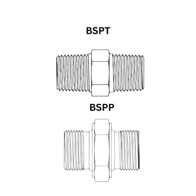
BSPT vs BSPP

BSPP (G): British Standard Pipe Parallel threads maintain a consistent diameter throughout, which prevents the sort of tapering typical of other thread types. This design is essential for applications requiring stable and uniform sealing pressure. BSPP fittings are generally used where the seal’s integrity is crucial, utilizing bonded seals or washers placed at the base of the thread to secure a leak-free connection.

BSPT (R): In contrast, British Standard Pipe Tapered threads narrow as they advance deeper into the fitting, providing a progressively tighter fit. This inherent taper allows for a metal-to-metal seal, which becomes more effective as the fitting is tightened, enhancing its ability to handle systems operating under variable pressures.

Sealing Features: The choice of sealing method is crucial in preventing fluid leakage and maintaining system integrity.

BSPP Fittings typically incorporate elastomeric seals such as O-rings, which are positioned to compress against the mating surface, thereby creating a high-integrity seal that can withstand fluctuations in pressure and temperature.

BSPT Fittings rely on the metal-to-metal contact between the tapered threads and the female receptacle. This contact forms a dynamic seal that adjusts under pressure and can be particularly effective in environments where chemical compatibility and temperature resistivity are necessary.

BSP fittings are predominantly used in the United Kingdom and many Commonwealth countries, where British standards have been historically implemented. These regions include parts of Africa, India, Australia, and the Middle East, where the legacy of British engineering continues to influence local industries.

How to Distinguish Between BSP and Metric Fittings

Distinguishing between BSP and Metric fittings is essential for ensuring the correct parts are used in hydraulic systems, which can prevent leaks and component mismatches that lead to system failures.

Identification Tools and Techniques

Tools Needed

Thread Gauge: A crucial tool that allows you to measure the threads per inch (TPI) for BSP fittings and the pitch for Metric fittings.

Calipers: Used to measure the outer diameter of the threads accurately.

Thread Pitch Gauge: Specifically helpful for quickly determining the pitch of Metric threads.

Magnifying Glass: Useful for closely examining thread shape and any markings that indicate thread type.

Reference Charts: Having charts that delineate BSP and Metric thread specifications can be a quick reference to confirm your measurements.

Step-by-Step Identification Guide

Step 1: Measure the Diameter

Use the calipers to measure the outer diameter of the threads. Record this measurement. Remember, BSP diameters are typically expressed in inches, while Metric diameters are measured in millimeters. This initial measurement is critical as it provides the first indication of the fitting standard.

Elimination Process When measure Hydraulic Hose Fittings

Step 2: Determine the Thread Pitch or TPI

For Metric fittings, measure the distance between thread peaks in millimeters (pitch). For BSP fittings, count the number of thread peaks per inch (TPI). Align the gauge appropriately with the threads and ensure it matches perfectly to avoid measurement errors. This step helps further differentiate the standard by focusing on thread spacing.

Step 3: Inspect the Thread Profile

Visual Inspection: Use a magnifying glass or thread profile gauge to examine the thread shape closely. It’s crucial to observe the angle and sharpness of the threads.

Metric Threads: Look for a 60-degree angle between the threads, which are typically sharper and more defined. Metric threads are known for their precise, angular profile, which contributes to their efficient sealing capability.

BSP Threads: Identify a 55-degree thread angle. BSP threads tend to have a more rounded and less sharp profile compared to Metric threads. This slight roundness helps in creating effective seals in high-pressure systems.

Step 4: Check for Standard Markings

Inspect the fitting for any manufacturer’s markings that indicate the standard. Commonly, fittings are marked with ‘M’ for Metric or ‘BSP’ for British Standard Pipe. These markings are usually found on the body or the side of the fitting and can be a quick way to identify the type without detailed measurement.

Step 5: Consult Reference Charts

After gathering all your data, refer to a reference chart that lists specifications for BSP and Metric fittings. Match your measurements and observations to the specifications on the chart. This step is crucial as it helps confirm your findings and ensures you have correctly identified the type of fitting.

Common Mistakes

Identifying hydraulic fittings correctly is critical to maintaining system integrity. Here are some common errors that occur during the identification of Metric and BSP fittings, along with practical tips to avoid them:

Confusing Metric and BSP Threads Due to Similar Sizes:

Metric and BSP threads can sometimes be similar in size but differ significantly in thread pitch and type, leading to incorrect identification and compatibility issues.

Misreading Thread Pitch and TPI:

Incorrectly measuring the thread pitch for Metric or threads per inch (TPI) for BSP can result in the selection of incompatible parts, which may cause leaks or thread damage when forced together.

Overlooking Thread Damage or Wear:

Worn or damaged threads can be misleading during measurements, potentially resulting in erroneous identification.

Assuming All Fittings with the Same Appearance are Identical:

Fittings might look similar but could have different specifications; relying solely on visual cues without precise measurement can lead to mistakes.

Conclusion

Throughout this article, we have explored the critical distinctions between Metric and BSP hydraulic fittings—two predominant types of fittings essential in various hydraulic systems across industries. Proper identification of these fittings is not only crucial for system compatibility but also for ensuring operational efficiency and safety.

FAQ

What are Metric hydraulic fittings?

Metric hydraulic fittings are based on the International System of Units (SI) and use millimeters to measure thread diameter and pitch. They typically feature a 60-degree thread angle and are common in systems outside of North America, particularly in Europe and Asia.

What are BSP hydraulic fittings?

BSP hydraulic fittings conform to British standards with specifications measured in inches. They can have either parallel (BSPP) or tapered (BSPT) threads, with a characteristic 55-degree thread angle, predominantly used in the UK and Commonwealth countries.

How can I identify whether a fitting is Metric or BSP?

Measure the outer diameter and thread count (TPI for BSP, pitch for Metric). Metric threads are sharper with a 60-degree angle, while BSP threads are more rounded with a 55-degree angle. Also, check for any standard markings on the fittings.

Can Metric and BSP fittings be interchanged?

Generally, Metric and BSP fittings are not interchangeable due to differences in thread forms and angles, which can lead to leaks and fitting damage if forced together.

Why is it important to use the correct type of hydraulic fitting?

Using the correct fitting type ensures compatibility and integrity of the hydraulic system, prevents leaks, and maintains operational safety and efficiency.

What tools are needed to measure and identify Metric and BSP fittings?

Digital calipers to measure the outer diameter, a thread pitch gauge to identify the thread pitch or TPI, and possibly a magnifying glass to examine the thread profile closely.


More Posts

Quickly Identify Hydraulic Fittings

Quickly Identify Hydraulic Fittings

Quickly Identify Hydraulic Fittings: What Should You Do?

Table of Contents

Introduction

Misidentification can result in the installation of incompatible or inadequate fittings, leading to leaks, system inefficiencies, or worse, catastrophic failures. Thus, technicians and engineers must be adept at quickly and accurately identifying various types of fittings to ensure they match the specifications and demands of their systems. This article aims to arm professionals with practical tips and essential tools for the swift identification of hydraulic fittings in various field settings.

Types of Hydraulic Fittings

Hydraulic fittings play a pivotal role in connecting components within hydraulic systems, ensuring fluid flows efficiently and without leaks under high pressure. Understanding the types, their applications, and identification tips is crucial for professionals who handle hydraulic machinery.

Hydraulic Hose Fittings

Description and Visual Identification Tips:

Hydraulic hose fittings are designed to connect hoses to components like hydraulic cylinders, valves, and pumps. They typically feature a barbed end to grip the inside of a hose and may have a threaded or flanged end to connect to the system. These fittings are often made from strong metals like steel or brass to withstand high pressures. Visually, hose fittings are recognized by their robust construction and multiple ridges or barbs.

Common Applications and Examples:

These fittings are used extensively in mobile hydraulics, construction equipment, and industrial machinery. For example, an excavator uses hydraulic hose fittings to connect its hydraulic hoses to the hydraulic pump and cylinders, facilitating the smooth operation of its moving parts.

Hydraulic Adapters

Functionality and Distinguishing Features:

Hydraulic adapters are used to connect different types of fittings and are essential for transitioning between various thread types or sizes. They often come in shapes such as straight, elbow, or tee, with male and female ends of differing types. Adapters can be identified by their geometric shapes and the presence of different threading on each end.

Material Types and Their Implications:

Materials commonly used for adapters include stainless steel, carbon steel, and brass. The choice of material affects the fitting’s corrosion resistance and suitability for different fluids and environmental conditions. Stainless steel adapters are preferred in corrosive environments, while brass is typically used for lower pressure settings.

Quick Couplings

How They Work and Common Uses:

Quick couplings, or quick-connect fittings, allow for fast connection and disconnection of hydraulic lines without the need for tools. These fittings generally have a male part (the plug) and a female part (the socket) that snaps together with a simple push-pull action. They are equipped with seals to prevent leaks during disconnection and connection.

Quick Identification Guide for Rapid Deployment:

Quick couplings are identifiable by their push-pull locking mechanism and the presence of a release sleeve on the socket. They are widely used in applications requiring frequent disassembly or where flexibility is needed, such as in agricultural implements or industrial machinery maintenance.

Banjo Fittings

Characteristics and Unique Identification Markers:

Banjo fittings are named for their distinctive shape that resembles a banjo. These fittings have a hollow bolt passing through a perforated circular plate, allowing fluid to flow through the bolt. They are easily identified by this unique structure.

Usage Scenarios and Compatibility:

Banjo fittings are commonly found in automotive fuel, oil, and hydraulic brake systems where space is limited and bending of hoses is required. Their design allows for a compact connection without excessive bending of the hydraulic hose.

Ferrule Fittings

Detailed Description and How They Differ from Other Fittings:

Ferrule fittings consist of a circular clamp (ferrule) that tightens around the hose to secure it to the fitting body. These are typically used with softer hoses to provide a tight seal by compressing the hose between the ferrule and the fitting body.

Importance in Hydraulic Systems:

The ferrule creates a seal that can withstand high pressures, making these fittings essential for high-pressure applications like chemical processing or oil and gas delivery. They differ from other fittings in that they provide a permanent, leak-proof seal that is crucial for maintaining system integrity.

Identification Marks on Fittings

Accurate identification of hydraulic fittings in the field can significantly streamline maintenance and setup processes. Manufacturers often utilize specific marking systems on fittings to aid in this identification. Two common methods include hexagonal markings and cap identifications.

Hexagonal Markings

Nut identify

Explanation of Markings Found on Hexagonal Fittings:

Hexagonal fittings often feature small notches or markings on their hexagonal surfaces. These markings are not merely decorative; they provide essential information about the fitting’s standard and specifications. Typically, these are machined into the fitting during manufacturing and are designed to be easily visible to aid quick identification.

Decoding the Meaning of Single vs. Double Notches:

Single Notch: Generally indicates that the fitting adheres to British standards (BSPP, BSPT). These fittings are commonly used in applications requiring a reliable seal in the presence of high fluid pressure.

Double Notch: Indicates that the fitting conforms to American standards (NPT, JIC). This differentiation is crucial as mixing components from different threading standards can lead to leaks or thread damage.

Understanding these markings can prevent costly errors in system assembly, ensuring compatibility and functionality.

Cap Identification

cap identification

How to Use Markings on Fitting Caps for Identification:

Manufacturers may also place identification marks on the caps of fittings. These caps protect the fitting during shipping and handling but can also serve as a quick reference point for technicians. Markings on caps can include the type of thread, size, and sometimes the material of the fitting. For example, a cap might be marked with “M16x1.5” indicating a metric thread with a diameter of 16 mm and a pitch of 1.5 mm.

Visual Examples for Clarity:

To aid in understanding, visual examples of cap markings include:

A cap marked with “SS” typically denotes stainless steel material, suggesting suitability for corrosive environments.

A cap with “3/8 NPT” indicates a 3/8 inch National Pipe Tapered thread, common in general industrial applications.

These cap identifications, combined with other markings, allow field technicians to quickly verify fitting characteristics without the need for additional tools or reference materials, streamlining maintenance and ensuring system integrity.

Thread Appearance

The thread type of a hydraulic fitting is crucial for ensuring compatibility and seal integrity within hydraulic systems. Different industries and regions might favor specific thread types based on standards and requirements. Recognizing these thread types visually can save time and prevent the common pitfalls of mismatching components.

Overview of Common Thread Types

Characteristics of Common Thread Types:

JIC (Joint Industry Council): JIC threads are characterized by their 37-degree flare seating surface and are often used in high-pressure applications. They are similar in appearance to AN (Aerospace Number) fittings used in military applications.

SAE (Society of Automotive Engineers): SAE threads are also flared (usually at 45 degrees) and are typically used in automotive and heavy equipment applications. They are robust and designed for medium to high-pressure conditions.

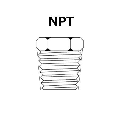
NPT (National Pipe Tapered): NPT threads are tapered and designed to provide a tight seal through the threading itself, making them ideal for plumbing applications. They require thread sealant or Teflon tape to ensure a leak-proof connection.

BSP (British Standard Pipe): BSP threads can be either parallel (BSPP) or tapered (BSPT). BSPP threads are commonly found in European equipment and require a bonded seal, while BSPT threads create a mechanical seal through thread engagement.

Metric: These threads are specified by the thread’s outer diameter and the pitch in millimeters, common in most non-North American equipment. Metric threads are straightforward and do not usually require flaring.

ORFS (O-Ring Face Seal): These have a flat sealing surface with an O-ring in a groove on the face of the fitting, providing an excellent seal. They are widely used in hydraulic systems where leakage is a critical concern.

Visual Comparison and Identification Tips:

Visually, JIC fittings can be distinguished by their shiny, metallic flare, while SAE fittings generally have a more pronounced thread and flared angle. NPT fittings taper towards the end, making them visually narrower at the tip than at the base. BSP threads are very uniform and symmetrical. Metric threads look very similar to BSP but are measured in metric units. ORFS fittings are recognizable by their flat face and visible O-ring.

Using Thread Charts and Gauges

How to Use Thread Charts Effectively:

Thread charts are essential tools for identifying thread types and sizes. These charts provide detailed illustrations and specifications of different threads. To use a thread chart effectively, measure the outer diameter of a male thread or the inner diameter of a female thread, then compare these measurements with the chart to determine the thread type and size.

Recommended Thread Gauges for Field Use:

Caliper-style Thread Gauge: Allows for quick and accurate measurement of the diameter and pitch of a thread.

Screw Pitch Gauges: Useful for determining the pitch of the thread by matching the teeth on the gauge with the thread.

Combination Gauges: These gauges combine features for measuring diameter, pitch, and thread type in one tool.

Carrying these gauges in the field allows technicians to quickly verify the thread type of a fitting, ensuring that replacements or repairs are done with the correct components, thus maintaining system integrity and function.

Determining Thread Angles

Thread angles are critical features in the identification and compatibility of hydraulic fittings, as they influence the type of seal formed and the fitting’s suitability for specific pressures and applications. Understanding how to measure and identify these angles can prevent equipment failures and maintain system integrity.

BSP vs NPT threads Topa

Thread Angle Identification

BSP (British Standard Pipe): BSP threads can be either parallel or tapered, but the thread angle is consistently set at 55 degrees. This angle helps in forming a tight seal when used with appropriate sealing washers or bonding compounds, particularly in high-pressure systems common in Europe.

Metric Threads: Metric threads, used predominantly outside of North America, generally feature a thread angle of 60 degrees. This angle is common across most metric fittings, making them slightly sharper compared to BSP threads. They are straightforward to identify due to their widespread use in automotive and industrial applications globally.

NPT (National Pipe Tapered): NPT threads have a unique feature of a 60-degree thread angle but are tapered, which allows the threads to form a seal as they are tightened. The tapering and angle are designed to mesh tightly as the male and female threads are screwed together, using the thread itself to form a seal, which is enhanced by thread sealants.

Practical Tips on Measuring and Identifying Thread Angles

Use a Thread Gauge: The most straightforward method to determine thread angles is to use a thread gauge, which can directly measure the angle formed at the thread’s peak. Simply place the gauge against the thread; if it fits perfectly, you have found the correct angle.

Calipers and Micrometers: For a more precise measurement, use calipers or micrometers to measure the outer and inner diameters of the threads. Once you have these measurements, refer to a thread identification chart to determine the angle based on known standards.

Visual Comparison: Often, a trained eye can distinguish between the slightly different angles of Metric (60 degrees) and BSP (55 degrees) threads through visual inspection, especially when they have samples for comparison. This method is quick and useful in field conditions where precise instruments may not be available.

Consult Technical Specifications: When possible, consult the technical specifications of the fitting. Manufacturers often provide detailed diagrams and specifications, including thread angles, which can be invaluable for verification.

When to Contact the Manufacturer

Unusual or Custom Fittings: If the fitting in question is not standard or appears to be custom-made for specific equipment, manufacturer insights can provide necessary specifications and replacement details.

Obsolete or Discontinued Parts: When dealing with older or discontinued models, the manufacturer can often suggest modern equivalents or provide sources for obtaining rare parts.

Safety-Critical Applications: For fittings used in critical safety applications, such as aerospace or chemical processing, confirming specifications with the manufacturer ensures compliance with safety standards and regulatory requirements.

Complex Assemblies: In systems with complex integration of various fitting types, manufacturers can offer assembly diagrams and compatibility guidance to avoid errors in reassembly after maintenance or repair.

Conclusion

The ability to quickly and accurately identify hydraulic fittings in the field is a critical skill for technicians and engineers working in the maintenance and assembly of hydraulic systems. Professionals should keep abreast of industry standards and new developments. The tips and strategies outlined in this guide are designed not only to improve individual skills, but also to foster a culture of precision and safety that benefits the industry as a whole. If you are still in any doubt, feel free to contact Topa!

FAQ

What are the most common types of hydraulic fittings?

The most common types include JIC (Joint Industry Council), SAE (Society of Automotive Engineers), NPT (National Pipe Tapered), BSP (British Standard Pipe), Metric, and ORFS (O-Ring Face Seal).

How can I visually distinguish between JIC and SAE fittings?

JIC fittings have a 37-degree flare, and SAE fittings typically have a 45-degree flare. The difference in the angle of the flare is visually noticeable when compared side by side.

What is the best way to determine the thread type of a hydraulic fitting?

Use a thread gauge to measure the pitch and diameter of the thread. Comparing these measurements with a thread identification chart can confirm the type.

Can NPT and BSP threads be interchanged?

No, NPT and BSP threads should not be interchanged. NPT threads have a different taper and pitch compared to BSP threads, which can lead to leaks and thread damage if forced together.

Why is it important to identify hydraulic fittings correctly?

Correct identification ensures compatibility and seal integrity, which are crucial for preventing leaks and maintaining system pressure and efficiency.

What tools are essential for identifying hydraulic fittings in the field?

Essential tools include calipers for measuring dimensions, thread gauges for identifying thread types, and possibly a reference book or mobile app with visual identifiers.

7 Common Mistakes When Measuring Hydraulic Fittings

7 Common Mistakes When Measuring Hydraulic Fittings

7 Common Mistakes When Measuring Hydraulic Fittings

Table of Contents

Introduction

Every connection in a hydraulic system is essential, as even the slightest miscalculation can lead to leaks, pressure drops, and failures that compromise the entire system’s integrity and safety. In this article, we will delve into the seven most common mistakes people make when measuring hydraulic fittings and provide practical tips on how to avoid them.

Using Inappropriate Tools

One of the most fundamental errors in measuring hydraulic fittings is the use of inappropriate tools. It’s a common scene in many workshops: a well-intended technician reaches for a standard tape measure or a ruler to size a hydraulic fitting. While these tools are handy for many tasks, they fall short of the precision required for hydraulic systems.

Commonly Misused Tools

Standard Tape Measures and Rulers: These tools are great for rough measurements but lack the precision for hydraulic fittings where even a millimeter can make a difference.

Adjustable Wrenches and Pliers: Often used to tighten or adjust fittings, these can damage the fitting if not sized correctly, affecting the integrity of the measurement and installation.

Appropriate Tools for Measuring Hydraulic Fittings

Calipers: Digital or Vernier calipers are perfect for measuring the outer diameter and thread pitch of hydraulic fittings. They provide the precision needed to ensure a perfect fit.

Thread Gauges: Essential for identifying the thread type and size, thread gauges help match the fitting precisely to its counterpart.

Micrometers: Used for highly precise measurements, especially in industrial applications where hydraulic fittings must meet stringent specifications.

hydraulic fittings measure tools Topa

Tips and Visual Comparisons

To help visualize the difference these tools can make, consider this simple guide:

Visual Tip: Always zero out your caliper before use to ensure accuracy. Check the caliper against a known measurement for calibration.

Comparison Image: Include an image showing a caliper measuring a hydraulic fitting next to a ruler holding the same fitting. This visual will highlight how the caliper provides a specific numerical measurement, whereas the ruler offers only a rough estimate.

Not Accounting for Thread Type

Hydraulic systems use a variety of thread types, each with specific characteristics and applications. Failing to identify and match these threads correctly can lead to improper fittings, leaks, and system failures. Understanding the different thread types and how to correctly identify them is crucial for anyone working with hydraulic fittings.

Overview of Different Thread Types

NPT (National Pipe Tapered): Common in North America, NPT threads are designed to create a tight seal through a taper that wedges the threads together, requiring the use of thread sealant.

BSP (British Standard Pipe): Used worldwide, BSP threads can be either parallel (BSPP) or tapered (BSPT). BSPP threads are generally used in water and gas fittings, requiring a bonded seal, while BSPT threads are often found in hydraulic systems.

Importance of Thread Types

Each thread type has a design that suits specific pressure ratings and sealing methods. Using the wrong type can prevent proper sealing and may damage components, leading to costly repairs and operational downtime.

How to Properly Identify Thread Types

Visual Inspection: Start by visually inspecting the fitting. Tapered threads narrow towards the end, while parallel threads maintain the same diameter.

Use of Thread Gauges: A thread gauge is an essential tool for identifying thread type and size. Simply match the gauge to the fitting’s threads to find the correct type.

Consult Specifications: Always refer to machinery or component specifications when available. These documents often list the required thread type.

Tips on Using Thread Gauges or Reference Charts

Regular Calibration: Ensure that your thread gauges are regularly checked for accuracy and are free from damage.

Clear Markings: Use gauges that have clear, legible markings to avoid confusion and errors in thread identification.

Ignoring Temperature and Pressure Factors

Temperature and pressure are critical factors that can significantly affect the dimensions and performance of hydraulic fittings. Ignoring these factors during measurement and installation can lead to improper fittings, resulting in leaks or mechanical failure under operational conditions.

How Temperature Affects Measurements

Expansion and Contraction: Materials expand when heated and contract when cooled. This thermal expansion can alter the effective size of hydraulic fittings. For instance, metal fittings may expand in high-temperature environments, leading to a looser fit once temperatures normalize.

Material Sensitivity: Different materials react differently to temperature changes. For example, metals typically expand more than plastics under the same temperature increase.

How Pressure Affects Measurements

Deformation: Under high pressure, materials may deform, especially if they are near their yield strength limits. This deformation can alter the sealing efficiency of hydraulic fittings.

Stress on Fittings: Continuous high-pressure loads can cause “creep,” a slow, permanent deformation of materials over time, affecting how fittings hold up.

Guidelines

Measure at Operating Temperature: Whenever possible, measure fittings at or near the operating temperature of the system to account for thermal expansion or contraction.

Use Temperature-Compensated Tools: Opt for measuring tools that are calibrated for use in varying temperatures or that can automatically compensate for temperature variations.

Allow for Pressure Variances: When designing systems that will operate under varying pressures, select fittings that can tolerate a range of deformations. For critical applications, consider using pressure-resistant fittings that are less likely to deform.

Material Selection: Choose materials based on their thermal and pressure characteristics suitable for the specific conditions they will encounter.

Overlooking Wear and Tear

Regular inspection and maintenance of hydraulic fittings are essential to ensure their functionality and safety. Over time, fittings can wear out, which not only impacts their effectiveness but also compromises the accuracy of measurements if not checked regularly. Here’s how to tackle the wear and tear of hydraulic fittings effectively.

rust Reusable Hydraulic Hose Fittings Topa

The Impact of Worn Fittings on Measurement Accuracy

Dimensional Changes: Wear and tear can lead to the erosion of material on hydraulic fittings, altering their original dimensions. This can result in improper fits, leaks, or complete system failures if the fittings are not compatible with the mating components.

Compromised Seals: As fittings wear out, the seals can become less effective, leading to leaks. Even small leaks can significantly affect the hydraulic system’s pressure and efficiency.

How to Inspect Fittings for Wear Before Measuring

Visual Inspection: Begin with a thorough visual inspection. Look for signs of erosion, rust, or any deformities on the fitting surfaces. Check for any visible cracks or scratches that could affect the fitting’s integrity.

Use Precision Measuring Tools: Utilize calipers or micrometers to measure the dimensions of the fittings. Compare these measurements against the specifications provided by the manufacturer to determine if the wear is within acceptable limits.

Check for Corrosion: Especially in systems exposed to harsh environments, check for signs of corrosion which can weaken fittings over time.

Suggest Maintenance or Replacement Intervals

Regular Scheduling: Establish a regular maintenance schedule based on the operational environment and the manufacturer’s recommendations. For example, in high-pressure systems or those in corrosive environments, more frequent checks are necessary.

Replacement Guidelines: As a rule of thumb, replace any fittings that show signs of significant wear or do not meet the dimensional specifications necessary for safe and efficient operation. Don’t wait for a failure to occur.

Record Keeping: Keep detailed records of inspections, maintenance, and replacements. This documentation can help predict wear trends and optimize maintenance schedules.

Preventive Tips

Lubrication: Regular lubrication can help reduce wear and tear by minimizing friction. Ensure that the correct type of lubricant is used for the specific material and operating conditions of the hydraulic fittings.

Upgrade Materials: Consider upgrading to more durable materials if current fittings wear out too quickly, especially in critical areas of the hydraulic system. Advanced materials like stainless steel or composites might offer better resistance to wear.

Neglecting Calibration of Measurement Tools

Accurate measurement is the cornerstone of properly fitting hydraulic systems, and the reliability of these measurements hinges on the precision of the tools used. Calibration of measurement tools ensures this precision is maintained over time. Neglecting this crucial step can lead to errors in measurement, resulting in improper fittings and potential system failures.

Importance of Regular Calibration

Accuracy Maintenance: Regular calibration helps maintain the accuracy of measurement tools. Over time, tools can drift from their original settings due to normal wear and tear.

Consistency: Calibration ensures that measurements are consistent over time and across different instruments and operators.

Compliance and Safety: Many industries have strict regulations regarding the accuracy of measurement tools, making regular calibration not just good practice but a legal requirement.

How to Calibrate Tools or Signs that Calibration is Needed

Signs Calibration is Needed:

Inconsistent Results: If measurements from the same tool vary without explanation or differ significantly from other instruments measuring the same item, it’s a strong indicator that calibration is needed.

Visible Damage or Wear: Any physical damage to measurement tools can affect their precision.

Time or Usage Milestones: Even absent visible signs, recalibrate tools at intervals recommended by the manufacturer or regulatory standards.

How to Calibrate Tools:

Use Standard Calibration Weights or Artifacts: For calipers and micrometers, use standard calibration weights or precision gauge blocks to check accuracy.

Professional Calibration Services: For complex tools or when high precision is necessary, it’s best to rely on professional calibration services that can provide certified accuracy.

Follow Manufacturer’s Instructions: Each tool may have specific calibration procedures outlined by the manufacturer, which should be followed meticulously.

Misreading Measurements

Misreading measurements can occur due to a variety of reasons, often leading to significant errors in the application of hydraulic fittings. Poor visibility or incorrect viewing angles are common culprits. Addressing these issues is critical to ensuring that measurements are accurate and reliable.

reusable hydraulic hose fittings measure length

Common Reading Errors Due to Poor Visibility or Angle

Poor Visibility: Inadequate lighting can make it difficult to see the markings on measurement tools clearly, leading to errors. Dust and dirt can also obscure scale markings on tools like calipers or rulers.

Incorrect Viewing Angle: Known as parallax error, this occurs when a measurement tool is not viewed directly from above. This skewed perspective can cause the reading to appear different from the actual measurement, leading to inaccuracies.

Techniques for Ensuring Accurate Readings

Enhance Lighting: Always work in well-lit areas to clearly see the tool markings. Use a portable lamp or flashlight if necessary to illuminate darker spaces.

Clean Tools Regularly: Keep the measurement tools clean and free of any debris that might interfere with the ability to read them accurately. A regular cleaning routine can prevent the build-up of grime that might obscure critical markings.

Direct Viewing: Make sure to view measurement scales straight on rather than at an angle. This direct approach minimizes parallax errors.

Use Digital Tools: Digital measurement tools, such as digital calipers, can significantly reduce reading errors as they display the measurement digitally, eliminating the need for interpreting fine lines.

Failing to Double-Check Measurements

In the precision-dependent world of hydraulic systems, failing to double-check measurements can lead to costly and potentially dangerous outcomes. Ensuring that every measurement is verified before proceeding with installations or adjustments is crucial for maintaining system integrity and performance.

The Consequences of Single Measurements

Increased Risk of Failure: A single unchecked measurement can be incorrect due to a variety of reasons such as tool error, human error, or environmental factors. This incorrect measurement can lead to improper fitting installations, resulting in leaks or pressure failures within hydraulic systems.

Costly Repairs and Downtime: Errors from incorrect measurements often result in system breakdowns that require costly repairs and cause significant operational downtime, affecting overall productivity and efficiency.

Safety Hazards: Inaccurate measurements can compromise the structural integrity of hydraulic systems, posing serious safety risks to operators and machinery.

Best Practices for Verification

Implement a Two-Check System: Always have measurements checked by a second person to eliminate the possibility of personal error or oversight.

Use Reliable and Calibrated Tools: Ensure that all measurement tools are regularly calibrated and maintained to provide accurate readings.

Document Measurements: Record all measurements in a logbook or digital system for accountability and future reference, which also aids in troubleshooting if discrepancies arise later.

A Checklist for Measurement Verification

To ensure thoroughness in measurement verification, follow this checklist:

Initial Measurement: Conduct the initial measurement with precision, taking care to position tools correctly and read them under proper lighting conditions.

Record Results: Write down the measurement immediately to avoid any memory errors.

Repeat Measurement: Use the same tool to measure the component again, or, better yet, a different tool calibrated to the same standard to verify consistency.

Independent Verification: Have another technician check the measurement using their tools and methods.

Compare With Specifications: Ensure that the measurement matches the specifications required for the part or system. Refer to technical drawings or manufacturer’s guidelines.

Check Environmental Factors: Consider any environmental factors that might influence the measurement, such as temperature and humidity, and adjust or compensate if necessary.

Conclusion

This guide is intended to enhance the practices of those working with hydraulic systems by providing actionable recommendations. By adhering to the best practices and validation processes outlined, technicians can ensure the reliability and safety of hydraulic installations, resulting in increased efficiency and longer system life.

FAQ

What is the most accurate tool for measuring hydraulic fittings?

Digital calipers are generally considered the most accurate tool for measuring the dimensions of hydraulic fittings, providing precise measurements critical for ensuring proper fit and function.

How often should measurement tools be calibrated?

Measurement tools should be calibrated regularly according to the manufacturer’s recommendations or at least once a year. More frequent calibration may be necessary if the tools are used heavily or in environments that could affect their accuracy.

How can I verify that my measurements are accurate?

To verify measurement accuracy, repeat the measurement with the same or a different calibrated tool, and if possible, have another technician confirm the measurements. Documenting all measurements and cross-referencing with specifications can also help ensure accuracy.

Can temperature affect the measurement of hydraulic fittings?

Yes, temperature can cause materials to expand or contract, which may affect the measurement of hydraulic fittings. It is important to measure fittings at a temperature close to their operating temperature to ensure accuracy.

What are the consequences of using worn or damaged hydraulic fittings?

Using worn or damaged hydraulic fittings can lead to leaks, pressure loss, and ultimately system failure. It is important to inspect fittings regularly for signs of wear and replace them as needed to maintain system integrity.

What is a thread gauge and why is it important?

A thread gauge is a tool used to measure the pitch or lead of screw threads. It is crucial to identify the correct thread type on hydraulic fittings to ensure compatibility and prevent leaks.

How to Install Quick Couplings

How to Install Quick Couplings

How to Install Quick Couplings?

Table of Contents

Introduction

Installing hydraulic quick connect fittings correctly is crucial for ensuring the efficiency and safety of hydraulic systems in various machinery and applications. These fittings offer a convenient way to connect and disconnect hydraulic lines without the need for tools, saving time and reducing the risk of fluid leaks. In this guide, we will walk you through the steps to install hydraulic quick-connect fittings properly, ensuring a secure and leak-free connection every time.

Overview of Hydraulic Quick Connect Fittings

What are Hydraulic Quick Connect Fittings?

Hydraulic quick connect fittings are specialized connectors used to swiftly join or disconnect hydraulic lines without the need for tools. These fittings are designed to facilitate efficient fluid transfer in hydraulic systems, commonly found in industrial machinery, construction equipment, and agricultural machinery. Their primary purpose is to simplify maintenance and reduce downtime by allowing for quick and easy connection and disconnection of hydraulic hoses and lines. Unlike traditional threaded or flanged connections, quick connect fittings minimize the risk of fluid leaks and contamination, enhancing the overall reliability and safety of hydraulic systems. Additionally, they are engineered to withstand high pressures and offer a secure, leak-free connection, making them an essential component in applications where efficiency and reliability are paramount.

Types of Hydraulic Quick Connect Fittings

Hydraulic quick-connect fittings come in various types, each suited for specific applications and offering unique advantages:

Ball-Type Quick Connect Fittings:

These fittings use a ball-locking mechanism to secure the connection. Ideal for general-purpose hydraulic systems and applications requiring frequent connections and disconnections.


Flat Face Quick Connect Fittings:

Designed with flat mating surfaces that eliminate fluid loss during connection and disconnection. Commonly used in construction and agricultural equipment where cleanliness is critical.

Wingnut-Type Quick Connect Fittings:

Feature a wingnut mechanism for manual tightening and loosening. Typically used in systems where hand-tightening is sufficient, such as low-pressure hydraulic systems.

Push-to-Connect Fittings:

Allow for quick connection by simply pushing the hose into the fitting. Suitable for applications requiring quick assembly and disassembly, such as in laboratory or testing setups.

Pre-Installation Preparation

Gathering Necessary Tools and Materials

Before beginning the installation of hydraulic quick-connect fittings, it’s essential to gather all necessary tools and materials to ensure a smooth and efficient process. Having the right tools and materials at hand can significantly streamline the installation and enhance safety and efficiency.


Essential Tools

Key tools required for the installation include:

Adjustable Wrenches: These are crucial for tightening and loosening various fittings and connectors. They provide the flexibility to adjust to different sizes of fittings, making them versatile for different tasks.

Torque Wrench: This tool is essential for ensuring that the fittings are tightened to the manufacturer’s specifications, preventing over-tightening which can lead to damage or leaks.

Cleaning Supplies

Clean Cloth or Rag: A clean cloth or rag is necessary for wiping connections and ensuring that no debris or contaminants are present on the fittings before installation. This helps in maintaining the cleanliness and integrity of the hydraulic system.

Mild Solvent: For more thorough cleaning, a mild solvent compatible with your hydraulic fluid can be used to clean the mating surfaces of the connectors, ensuring that all contaminants are removed.

Hydraulic Fluid

Compatible Hydraulic Fluid: Ensure you have the correct type of hydraulic fluid that is compatible with your system. Using the wrong fluid can lead to system failure or damage to the fittings and hoses.

Pressure Rating: Choose fittings that match or exceed the pressure rating of your hydraulic system to prevent failures.

Fluid Compatibility: Ensure the fittings are compatible with the type of hydraulic fluid used in your system.

Application Requirements: Consider the specific requirements of your application. For instance:

Flat Face Fittings: Ideal for applications where cleanliness is crucial, such as in construction or agricultural equipment.

Ball-type fittings: Versatile for general use in various hydraulic systems, offering easy connection and disconnection.

Safety Gear

safety protection Topasafety protection Topa

Safety gear is critical to protect against potential hazards during the installation process. Essential safety gear includes:

Safety Glasses: Protect your eyes from hydraulic fluid splashes and potential debris.

Gloves: Safeguard your hands from sharp edges and high-pressure leaks, providing both protection and grip.

Protective Clothing: Prevents skin contact with hydraulic fluids, reducing the risk of irritation or chemical burns.

Step-by-Step Installation Guide

Inspecting the Equipment

Before installing hydraulic quick connect fittings, it is crucial to thoroughly inspect all hoses and connectors to ensure they are in good condition. This step is essential to prevent potential failures and ensure a secure, leak-free connection.

Visual Examination of Hoses

Check for Wear and Damage:

Cracks: Look for any visible cracks along the length of the hoses, as these can weaken the hose and lead to leaks.

Abrasions: Inspect for any areas where the hose surface appears worn or abraded, which can be a sign of friction or rubbing against other components.

Bulges: Identify any bulges, which may indicate internal damage or weak spots that could burst under pressure.

Focus on Connector Areas:

Stress Points: Pay close attention to areas near the connectors, as these spots often experience the most stress and movement, making them more prone to wear and damage.


Inspection of Connectors

Check for Corrosion and Damage:

Corrosion: Look for any signs of rust or corrosion on the metal surfaces of the connectors, which can compromise the strength and integrity of the connection.

Damage or Deformation: Inspect for any visible damage or deformation, such as bent or misshapen connectors, which can prevent proper sealing.

Examine O-rings and Seals:

Intact O-rings: Ensure that all O-rings are present, properly seated, and free from cracks or wear. O-rings are crucial for creating a tight seal and preventing leaks.

Seal Integrity: Check that all seals are in good condition, without any signs of damage or deterioration.

Hydraulic Hose Inspection

Surface Inspection:

Check for Wear and Tear: Examine the entire length of the hose for signs of wear such as abrasions, cuts, or bulges. These can indicate weakened areas that are more susceptible to failure under pressure.

Inspect Outer Cover: Ensure the outer cover of the hose is intact without any significant signs of wear or exposure of the reinforcement layer.

Flexibility and Integrity:

Bend Test: Gently bend the hose to check for any stiffness, cracking, or brittleness. A hose that has become stiff or cracked should be replaced as it may not handle pressure well.

Check for Kinks: Ensure the hose does not have any permanent kinks or bends that could restrict fluid flow or cause undue stress on the hose material.

End Fittings Examination:

Inspect Fittings for Corrosion: Check the hose fittings for signs of corrosion or rust, which can weaken the connection and lead to leaks.

Verify Secure Attachment: Ensure that the fittings are securely attached to the hose with no visible gaps or looseness. This is especially important for crimped fittings.

Pressure Rating Verification:

Check Hose Specifications: Verify that the hose’s pressure rating matches the requirements of your hydraulic system. Using a hose with an inadequate pressure rating can lead to catastrophic failure.

Replacement of Damaged Components

Identify and Replace:

Damaged Hoses: If any hoses show signs of significant wear or damage, replace them with new ones to maintain system integrity.

Faulty Connectors: Replace any connectors that exhibit corrosion, damage, or deformation to ensure a secure and reliable connection.

Cleaning the Connectors and Hoses

Cleaning the connectors and hoses before installation is essential to prevent contamination and ensure a secure, leak-free connection. This step helps maintain the hydraulic system’s efficiency and prevents contamination-related issues.

Initial Cleaning

Wipe Down Exterior Surfaces:

Use a Clean, Lint-Free Cloth: Start by wiping down the exterior of the hoses and connectors with a clean, lint-free cloth to remove any surface dirt or debris. This preliminary cleaning helps ensure that no large particles are present that could enter the hydraulic system during installation.

Inspect for Remaining Debris: After wiping, inspect the components to ensure all visible dirt and debris have been removed.

Thorough Cleaning

Using a Mild Solvent:

Choose a Compatible Solvent: Select a mild solvent that is compatible with your hydraulic fluid. Compatibility is crucial to avoid chemical reactions that could damage the hydraulic components or the fluid.

Apply Solvent to Cloth: Dampen a clean cloth with the chosen solvent. Avoid soaking the cloth to prevent excess solvent from running into the connectors.

Cleaning Mating Surfaces:

Gently Wipe Mating Surfaces: Use the solvent-dampened cloth to wipe the mating surfaces of the connectors gently. Focus on removing any fine particles, grease, or residues that could interfere with the sealing surfaces.

Avoid Abrasive Materials: Do not use abrasive materials such as steel wool or harsh brushes, as these can scratch or damage the connectors, compromising their ability to form a tight seal.

Drying the Components

Air Drying:

Allow Components to Air Dry: After cleaning, place the connectors and hoses in a clean, dry area and allow them to air dry completely. Ensure they are not exposed to contaminants or moisture during the drying process.

Inspect After Drying: Once dry, inspect the components again to ensure no solvent residue remains and that all surfaces are clean and ready for installation.

Apply Thread Sealant

Install Quick Couplings

Select Appropriate Sealant:

When choosing a thread sealant, it is essential to select one that is specifically designed for hydraulic systems. Verify that the sealant or PTFE tape you select is compatible with the hydraulic fluid being used, as well as the temperature and pressure conditions of your system. This compatibility ensures the sealant will not degrade or react adversely with the fluid or system components.

Sealant Application:

For Liquid Sealant: Apply a uniform bead of the liquid sealant around the entire circumference of the male threads on the coupling. It is important to avoid excessive application, as too much sealant can be pushed into the hydraulic system, potentially leading to contamination or blockage.

For PTFE Tape: Wrap the PTFE tape around the male threads, starting at the end of the thread and working back towards the base. Overlap each layer of tape slightly, typically wrapping 2-3 complete turns. Ensure the tape is applied in the direction of the thread to prevent it from unraveling when the coupling is screwed onto the hose fitting.

Attach the Coupling

Initial Hand-Tightening:

Begin threading the coupling onto the hose fitting by hand. Turn the coupling clockwise until it is snug and you meet resistance. This initial hand-tightening helps align the threads properly and reduces the risk of cross-threading, which can damage both the coupling and the hose fitting.

Wrench Tightening:

After hand-tightening, use an appropriate-sized wrench to continue tightening the coupling. Apply steady pressure and turn the coupling an additional 1 to 1.5 turns beyond hand-tight. This ensures a secure fit without overtightening, which can strip the threads or damage the coupling and hose connection. Always check the manufacturer’s specifications for the recommended torque settings if available.

Testing

Re-pressurize the System:

Slowly reintroduce hydraulic pressure to the system.

Gradually restore hydraulic pressure to the system to avoid any sudden surges that could disrupt the new connections. Monitor the pressure gauge and increase the pressure incrementally, ensuring the system stabilizes at each step.

Check for Leaks:

Inspect the coupling area for any signs of leaks.

Carefully examine the coupling and surrounding areas for any signs of hydraulic fluid leaks. Use a clean, dry cloth or tissue to wipe around the connection, and watch for any dampness or fluid seeping out.

If leaks are detected, depressurize the system again before making adjustments. Tighten the coupling slightly more if necessary, or remove it to reapply thread sealant or PTFE tape, and then reattach following the previous steps. Re-test to confirm a leak-free connection.

Drying the Components

Air Drying:

Allow Components to Air Dry: After cleaning, place the connectors and hoses in a clean, dry area and allow them to air dry completely. Ensure they are not exposed to contaminants or moisture during the drying process.

Inspect After Drying: Once dry, inspect the components again to ensure no solvent residue remains and that all surfaces are clean and ready for installation.

Common Errors Prone to Occur

Cross-Threading:

Cross-threading occurs when the threads of the coupling and hose fitting are not properly aligned before tightening. This can damage the threads and create a poor seal, leading to leaks.

Over or Under Tightening:

Over-tightening can strip the threads or damage the coupling and hose fitting, while under-tightening may result in a loose connection and potential leaks.

Improper Sealant Application:

Using too much or the wrong type of thread sealant can lead to contamination of the hydraulic system or failure of the seal.

Ignoring Pressure Testing:

Failing to properly test the system for leaks after installation can result in undetected leaks and potential system failures.

Conclusion

In this comprehensive guide, we covered the essential steps for correctly installing hydraulic quick connect fittings. Proper installation and regular maintenance are crucial for ensuring the efficiency and safety of hydraulic systems. By following these guidelines, you can achieve secure, leak-free connections that enhance the performance and reliability of your hydraulic equipment.

FAQ

What are the benefits of using hydraulic quick couplings?

Hydraulic quick couplings allow for easy and quick connection and disconnection of hydraulic lines without the need for tools. They help reduce downtime, prevent fluid leaks, and simplify maintenance processes in hydraulic systems.

How can I ensure a secure connection when installing hydraulic quick couplings?

To ensure a secure connection, align the male and female connectors properly, engage the locking mechanism fully, and tighten threaded fittings to the manufacturer’s specified torque using an adjustable wrench. Always check for proper alignment and inspect for any leaks after connecting.

What safety precautions should I take when installing hydraulic quick couplings?

Always depressurize the hydraulic system before starting the installation. Wear appropriate safety gear such as safety glasses, gloves, and protective clothing. Ensure all connectors and hoses are clean and free from debris to prevent contamination.

How do I choose the right hydraulic quick coupling for my system?

Select hydraulic quick couplings based on the system’s pressure rating, the type of hydraulic fluid used, and specific application requirements. For example, use flat-face couplings for applications where cleanliness is crucial and ball-type couplings for general-purpose applications.

What should I do if I notice a leak after installing a hydraulic quick coupling?

If you notice a leak, immediately depressurize the system and check the alignment and tightness of the connectors. Re-tighten if necessary, and inspect the O-rings and seals for damage. Replace any faulty components and re-test the connection.

Can I reuse hydraulic quick couplings after disconnection?

Yes, hydraulic quick couplings are designed for repeated use. However, always inspect the couplings for wear, damage, or contamination before reconnecting. Ensure that the O-rings and seals are in good condition and replace them if needed to maintain a secure connection.

More Posts

How a Hydraulic System Works Efficiency & Optimization

How a Hydraulic System Works

How a Hydraulic System Works: Efficiency & Optimization

Introduction

Hydraulic systems are an integral part of modern machinery, transmitting power through fluid pressure and flow. Central to maximizing the potential of a hydraulic system are the twin principles of efficiency and optimization. Efficiency in a hydraulic system means achieving maximum output with minimum energy loss. Optimization, on the other hand, is the fine-tuning of system components and operations to achieve optimal performance. This paper will take an in-depth look at the fundamental aspects of hydraulic systems, highlighting their role in a variety of industries and the importance of optimizing these systems for efficiency.

Understanding Hydraulic Systems

Introduction to Hydraulic Principles

Hydraulic systems operate on a simple yet powerful principle: the ability to transmit force through a fluid, typically oil, under pressure. This is based on Pascal’s Law, which states that pressure exerted anywhere in a confined incompressible fluid is transmitted equally throughout the fluid such that it acts with equal force on equal areas, in all directions. This principle is foundational in hydraulic systems, enabling the exertion of high forces or the execution of precise movements in heavy machinery.

Exploring Key Components

Hydraulic Pumps: These are the heart of the hydraulic system, responsible for moving the fluid from the reservoir through the system. Different types of pumps include gear pumps, which are known for their durability and simplicity; vane pumps, offering variable displacement options; and piston pumps, known for their high pressure and efficiency.

Valves: Valves in a hydraulic system control the flow and direction of the hydraulic fluid. Directional control valves manage the path of the fluid, whereas pressure relief valves protect the system from excessive pressure. Control valves adjust the flow rate and thereby the speed of the actuators.

Actuators: Hydraulic actuators convert the energy of the hydraulic fluid into mechanical motion. Hydraulic cylinders provide linear motion, while hydraulic motors offer rotary motion, enabling the operation of various types of machinery.

Reservoirs: The reservoir holds the hydraulic fluid. Its roles include not just storage, but also cooling and filtering the fluid. Maintaining clean and temperature-controlled fluid is essential for the system’s performance and longevity.

System Dynamics and Component Interplay

In a hydraulic system, all components must work in concert for efficient operation. The pump sends hydraulic fluid into the system under pressure. This fluid travels through valves, which direct it to various actuators based on the operation’s requirements. The actuators then convert this hydraulic energy into mechanical energy, performing the needed work, whether it’s lifting, pushing, or rotating. After transmitting its energy, the fluid returns to the reservoir, where it is prepared for another cycle.

Hydraulic Fluids

The choice of hydraulic fluid is critical as it affects the efficiency and safety of the entire system. Different types of fluids are used based on the operational environment and machinery requirements. The fluid must have suitable viscosity for the system’s temperature range, good lubricating properties, and must be resistant to forming foam and emulsions.

hydraulic fluid Topa

Control Systems and Feedback Loops

Modern hydraulic systems often integrate electronic control systems and feedback loops. These systems allow for precise control of the hydraulic actuators, leading to more efficient, responsive, and sophisticated machinery operation. They can adjust the flow and pressure of the fluid dynamically, responding to the immediate requirements of the machinery and its load, thereby optimizing the performance and energy usage of the system.


Factors Affecting Efficiency in Hydraulic Systems

Efficiency in hydraulic systems is significantly affected by several factors including the properties and selection of hydraulic fluid, system design and layout, and the quality and compatibility of components.

Hydraulic Fluid Properties and Selection

The hydraulic fluid is a key element in any hydraulic system. Its properties directly impact the system’s efficiency. Fluid viscosity is crucial; too thick, and it will resist flow and increase the energy needed to pump it, too thin, and it will fail to lubricate effectively and lead to increased wear. The fluid should also have good lubrication properties to reduce friction and wear in the system. Additionally, its chemical composition should be stable under the range of operating temperatures and pressures. Selecting the right hydraulic fluid involves considering the system’s operational environment, including temperature extremes and potential contaminants.

Role of System Design and Layout

Efficient system design optimizes the flow of hydraulic fluid and minimizes energy losses. This involves proper sizing of components, including pipes, hoses, and valves, to ensure adequate flow while avoiding excessive pressure drops. The layout of the system should also be considered to prevent heat build-up and to facilitate maintenance and inspection. Design considerations also include the placement of components to minimize the length of hydraulic lines, reducing the potential for leaks and inefficiencies.

Importance of Component Quality and Compatibility

The quality of components in a hydraulic system plays a vital role in its efficiency. Higher-quality components tend to have better tolerances, more robust materials, and better resistance to wear and tear. Compatibility of components is also crucial. Components not designed to work together can cause inefficiencies in the system due to mismatches in size, pressure ratings, or material incompatibilities. Regular inspection and maintenance are key to ensuring the components function well together over the life of the system.

Each of these factors plays a substantial role in determining the efficiency of a hydraulic system. By understanding and addressing them, one can ensure the system operates at its optimal performance, reducing energy usage and increasing the lifespan of the components.

Common Challenges in Hydraulic Systems

Hydraulic systems are prone to several challenges that can affect their performance, efficiency, and longevity.

Leaks and Contamination

One of the most common issues in hydraulic systems is leaks. These can occur due to wear and tear on seals and hoses or through faulty connections. Leaks not only lead to a loss of hydraulic fluid but can also introduce contaminants into the system. Contamination, particularly by water, air, or particulate matter, can severely affect the system’s performance. It leads to corrosion, increased wear on components, and can significantly reduce the efficiency of the system.

Pressure Fluctuations and Overheating

Another challenge is the management of pressure fluctuations. These can arise from various factors, including air entrapment in the fluid or issues with the hydraulic pump. Inconsistent pressure can result in erratic system performance and can be damaging to the machinery. Overheating is a related concern and can be caused by inadequate cooling, environmental factors, or operating the system beyond its capacity. Overheating can degrade the hydraulic fluid, leading to reduced performance and potential damage to the system.

Wear and Tear of Components

Regular use of hydraulic systems inevitably leads to wear and tear of its components. This is a natural process but can be accelerated by factors such as contamination, inadequate maintenance, or operating the system in extreme conditions. Wear and tear can decrease the efficiency of the system and, if not addressed, can lead to system failure.

Proactive maintenance and monitoring of hydraulic systems are essential in addressing these challenges. Regular checks can identify potential leaks and contamination early, pressure levels can be monitored to ensure stable operation, and components can be inspected for signs of wear and tear.

Strategies for Optimization

Enhancing the efficiency of hydraulic systems is crucial for both performance and sustainability. This involves a systematic approach that includes regular maintenance and monitoring, employing advanced technological solutions, and retrofitting or upgrading existing systems to meet current standards of efficiency and performance.

Regular Maintenance and Monitoring

Comprehensive maintenance is the cornerstone of hydraulic system optimization. This involves regular inspections, proactive replacement of worn or damaged components and ensuring the integrity of seals and hoses to prevent leaks. Regularly changing hydraulic fluids and filters is also essential to maintain the cleanliness and efficiency of the system. Monitoring entails checking system pressures, temperatures, and fluid levels to detect any signs of malfunction or inefficiency early on.

Advanced Technologies for System Monitoring and Diagnostics

The integration of advanced technologies plays a pivotal role in the optimization of hydraulic systems. The use of sensors and real-time monitoring equipment allows for the continuous tracking of system performance. These technologies can provide valuable data on the system’s operational parameters, enabling predictive maintenance and immediate corrective actions. Diagnostic software and tools facilitate the quick identification of potential issues, reducing downtime and preventing major breakdowns.

Retrofitting and Upgrading Existing Systems

Upgrading and retrofitting existing hydraulic systems with new technology and components can significantly enhance their efficiency. This could involve installing more efficient pumps and motors, upgrading control valves for better flow regulation, or integrating advanced filtration systems. Retrofitting older systems with modern electronics and control systems can also provide finer control, increased precision, and improved energy efficiency. These upgrades not only improve performance but also extend the lifespan of the hydraulic systems, making them more sustainable and cost-effective in the long run.

In conclusion, optimizing hydraulic systems through these strategies is essential for maintaining their operational efficiency, reducing environmental impact, and minimizing operational costs. By combining regular maintenance, advanced technology, and strategic upgrades, hydraulic systems can achieve optimal performance and reliability.

Conclusion

Wrapping up, the exploration of hydraulic systems has highlighted their pivotal role across various industries. We’ve navigated through the intricacies of these systems, from understanding their basic components to delving into the advancements in hydraulic fluid technology. The significance of skilled operation and the impact of emerging technologies in enhancing efficiency were underscored. As we look ahead, the trends point towards smarter, more sustainable hydraulic systems. This journey reaffirms the necessity of continual efficiency optimization in hydraulic systems, balancing operational needs with environmental stewardship.


Conclusion

Hydraulic systems typically consist of a reservoir tank, hydraulic pump, pipes and hoses, motor, valves, actuators, and filters.

Hydraulic systems operate by using a fluid (usually oil) pumped from a reservoir through pipes and valves to an actuator, where it exerts force on a piston, creating motion .

The two primary types are open-loop and closed-loop systems. Open-loop systems do not maintain pressure when idle, while closed-loop systems maintain pressure and typically utilize a feed or charge pump.

Extreme temperatures can negatively impact hydraulic systems; high temperatures can decrease the viscosity of hydraulic oil, affecting its lubrication ability, while low temperatures can increase oil viscosity and make the system less efficient​.

Regular maintenance includes checking fluid levels and quality, inspecting for leaks, and changing filters to maintain system efficiency and prevent malfunctions.

Due to the high pressure under which hydraulic systems operate, it’s crucial to handle them carefully, adhere to safety guidelines, and perform regular checks to prevent accidents.

Common troubleshooting steps include checking for leaks, ensuring proper fluid levels, and inspecting components for wear and damage.

Factors include the required oil flow rate, desired working pressure, and the hydraulic cylinder’s oil volume displacement.

Hydraulic cylinder failures can often be attributed to side loading, which misaligns the cylinder and creates uneven forces on the piston rod.

Single-acting cylinders use hydraulic fluid for motion in one direction only, while double-acting cylinders use fluid for both extending and retracting movements​.

9 Shocking Flange Fitting Failures You Can Easily Avoid

9 Shocking Flange Fitting Failures You Can Easily Avoid

9 Shocking Flange Fitting Failures You Can Easily Avoid

Table of Contents

Introduction

This article delves into the critical role of flange hydraulic fittings within industrial piping systems, emphasizing their importance in maintaining fluid flow under various operational conditions. It outlines the potential risks associated with flange hydraulic fitting failures, including leaks and industrial accidents, thereby highlighting the necessity of proper understanding, installation, and maintenance of these components. Through this discussion, the article aims to provide insights into ensuring the safety and efficiency of industrial operations by focusing on the correct practices related to flange fittings.

Understanding Flange Hydraulic Fittings

Flange hydraulic fittings are components that connect sections of pipes, valves, pumps, and other equipment within piping systems. Their primary function is to facilitate the assembly and disassembly of these systems for maintenance and repair purposes. These fittings are available in a range of shapes and sizes, tailored to meet specific operational demands such as pressure, temperature, and flow rates.

Industrial Applications

Flange hydraulic fittings are utilized in a wide array of industries. Key sectors include oil and gas, water treatment, and manufacturing. Their use across these diverse fields underscores their critical role in maintaining operational continuity and safety. The deployment of flange hydraulic fittings in critical industrial applications underlines their essential role in the seamless operation of piping systems. Their design and functionality ensure that systems can handle the required pressures and temperatures, thus safeguarding against potential failures and ensuring system integrity.

The Top 10 Flange Hydraulic Fitting Failures

Using Mismatched Flange and Pipe Sizes

Risks of Mismatch

When flange and pipe sizes are mismatched, the consequences can be immediate and severe. Even the slightest discrepancy in size can lead to gaps that compromise the seal, resulting in leaks. These leaks not only pose risks to safety and environmental standards but also lead to operational inefficiencies, including the loss of valuable resources and potential shutdowns for repairs. Moreover, mismatches can introduce undue stress on the pipeline, accelerating wear and tear and leading to premature failure of components.

Ensuring Correct Sizing

Preventing the pitfalls associated with mismatched flange and pipe sizes requires a meticulous approach throughout the lifecycle of the piping system:

  • Design Phase: During the design phase, accurate specifications for both flanges and pipes must be established, ensuring that all components are compatible in size. This step often involves detailed engineering calculations and a thorough understanding of the operational requirements of the system.
  • Procurement Process: When ordering flanges and pipes, double-checking the specifications is crucial to avoid mismatches. This includes verifying the nominal size, pressure rating, and other relevant standards to ensure they match the system’s design specifications.
  • Installation and Assembly: During installation, careful examination of the flanges and pipes to ensure size compatibility is essential. This includes checking for any deviations in the specifications of the received components from those ordered.
  • Ongoing Maintenance: Regular maintenance and inspections should include checks for signs of leaks, which could indicate sizing issues or wear and tear that has led to a mismatch over time. Addressing these issues promptly can prevent more significant failures.

Ignoring Flange Ratings

Flange ratings are a crucial aspect of flange fittings in piping systems. These ratings indicate the maximum pressure the flange can withstand at a specific temperature. Flange ratings ensure the safe operation of piping systems under various conditions. They are determined based on standards such as ASME B16.5 or the equivalent, which consider factors like material strength and design.

Consequences of Ignoring Flange Ratings

Failure to adhere to these ratings can result in:

  • Leaks: When the system operates beyond the rated capacity, it may cause gasket failure or deformation, leading to leaks.
  • Flange Failure: Exceeding the pressure rating can cause the flange itself to fail, which might result in a burst or catastrophic failure of the piping system.
  • System Downtime: Any failure requires repairs or replacement, leading to operational downtime and financial losses.

Preventative Measures

  • Selection: Ensure that the selected flange meets or exceeds the system’s maximum operating pressure and temperature.
  • Installation: Proper installation according to the flange and gasket manufacturer’s guidelines is crucial to maintain the integrity of the flange connection.
  • Inspection and Maintenance: Regular inspections can identify potential issues before they lead to failure. Maintenance should include checking for signs of wear, corrosion, or damage.

Neglecting Proper Gasket Selection

hydraulic flange seal

Gaskets are essential for creating a leak-proof seal between flange connections in piping systems. The selection of gaskets involves choosing the right material and size to match the operational conditions of the system. The material of the gasket must be compatible with the fluids being transported in the system to prevent chemical degradation. Common gasket materials include rubber, PTFE, and graphite, each with distinct properties suitable for different applications. The size and thickness of the gasket must precisely match the flanges to ensure a complete seal. Incorrect sizing can lead to gaps or excessive compression, both of which can compromise the seal’s integrity.

Temperature and Pressure Considerations

Gaskets must be selected based on the temperature and pressure conditions of the system. High temperatures or pressures require gaskets made from materials that can maintain their sealing properties under these conditions.

Overlooking Bolt Tightening Sequence

Bolt tightening sequence is crucial for ensuring the integrity of flanged connections in piping systems. This sequence impacts how evenly pressure is distributed across the flange, affecting the overall seal and stability of the connection.

Impact of Incorrect Sequence

Not following the correct sequence can lead to uneven pressure distribution. This imbalance can cause areas of the gasket to be compressed more than others, leading to potential leaks and reducing the effectiveness of the seal. Over time, this uneven pressure can also contribute to the degradation of the flange and gasket, leading to potential failures.

Correct Sequence for Bolt Tightening

The standard practice involves tightening bolts in a star pattern, similar to the method used for car wheel nuts. This approach ensures that pressure is applied evenly across the entire flange. The process typically involves several passes at increasing torque values to gradually and evenly compress the gasket and secure the flange.

Initial Hand Tightening: Bolts should be initially tightened by hand to ensure that the gasket is positioned correctly and that there are no gaps.

  • First Pass: Using a torque wrench, the bolts are tightened in a star pattern to a specified fraction of the final torque value, often 30% to 50%.
  • Subsequent Passes: Additional passes are made, increasing the torque value with each pass until the final torque specification is reached.
  • Final Check: A final pass is made to verify that all bolts have been tightened to the correct torque.

Using Damaged or Worn Flanges

worn flange fitting Topa

The condition of flanges in a piping system is critical to maintaining the integrity and safety of the operation. Flanges that are damaged or worn can compromise the system, leading to failures that may have severe consequences.

Risks of Using Damaged or Worn Flanges

Using flanges that are not in optimal condition can lead to several issues:

  • Leaks: Damaged or worn flanges may not seal properly, leading to leaks that can affect system efficiency and safety.
  • System Failure: In severe cases, the failure of a damaged or worn flange can result in system breakdown, causing operational disruptions and potential safety hazards.
  • Increased Maintenance Costs: Using compromised flanges can lead to more frequent repairs and maintenance, increasing operational costs.

Importance of Regular Inspections

To prevent the risks associated with using damaged or worn flanges, regular inspections are essential. These inspections should assess the flanges for:

  • Physical Damage: Checks for cracks, warping, or other physical damage that could impair the flange’s ability to form a seal.
  • Corrosion: Inspection for signs of corrosion that can weaken the flange and make it susceptible to failure.
  • Wear: Evaluation of the flange surface for signs of wear that could prevent a proper gasket seal.

Corrective Actions

When damaged or worn flanges are identified, the following corrective actions should be taken:

  • Replacement: Flanges that are significantly damaged or worn should be replaced to ensure the integrity of the piping system.
  • Repair: In some cases, minor damage may be repairable. However, this should only be done if the repair can restore the flange to a condition where it can safely perform its intended function.
  • Upgrading: If recurrent issues with flanges are identified, it may be necessary to upgrade to flanges made of more durable materials or designs that better suit the operational conditions.

Incorrect Flange Alignment

Flange alignment in piping systems plays a crucial role in ensuring a tight and efficient seal between connections. Proper alignment is necessary to distribute pressure evenly and maintain the integrity of the seal, preventing potential leaks and failures.

Consequences of Misalignment

Misalignment of flanges can result in several issues within the piping system:

  • Uneven Pressure Distribution: When flanges are not aligned correctly, it can lead to uneven pressure distribution across the gasket. This uneven pressure can cause the gasket to fail, resulting in leaks.
  • Increased Stress on Piping Components: Incorrect alignment may also put additional stress on pipes, flanges, and bolts, leading to accelerated wear, fatigue, and eventual failure of these components.
  • Reduced System Efficiency: Leaks and failures due to misalignment can significantly reduce the efficiency of the piping system, leading to increased maintenance costs and downtime.

Ensuring Correct Alignment

To avoid the issues associated with incorrect flange alignment, the following steps should be taken:

  • Use of Alignment Tools: Specialized tools and techniques should be employed to ensure flanges are aligned correctly before bolting. This may include the use of flange alignment pins or levels.
  • Inspection and Adjustment: Flanges should be visually inspected for alignment as part of the assembly process. Any misalignment detected should be corrected before proceeding with the bolting and sealing process.

Failure to Use the Correct Lubrication

Lubrication in flanged connections is critical for the proper tightening of bolts and effective compression of gaskets. It plays a pivotal role in achieving the desired seal integrity and longevity of the flange assembly.

Consequences of Inappropriate Lubrication

Using incorrect or inadequate lubrication can lead to several issues:

  • Compromised Bolt Integrity: Incorrect lubrication may affect the torque applied to bolts, leading to under or over-tightening. This can strain the bolts, reducing their lifespan and potentially causing them to fail.
  • Gasket Performance: Without proper lubrication, gaskets may not compress evenly or sufficiently, resulting in leaks. This undermines the integrity of the flange connection and the overall system.
  • Leakage and Reduced Flange Life: Inadequate lubrication can accelerate wear on both the gasket and the flange surfaces, leading to early failure and reduced operational life of the flange assembly.

Selecting the Correct Lubrication

To ensure the longevity and reliability of flange connections, the correct lubrication must be selected based on:

  • Compatibility with Gasket Material: The lubricant should not degrade the gasket material. Compatibility charts or manufacturer recommendations can guide the selection process.
  • Operating Conditions: The lubricant must withstand the environmental and operational conditions (e.g., temperature, pressure, exposure to chemicals) of the system without losing its properties.
  • Ease of Application: The chosen lubricant should be easy to apply uniformly across all bolt threads and gasket surfaces to ensure consistent performance.

Not Accounting for Thermal Expansion

Thermal expansion is a natural phenomenon where materials expand upon heating and contract when cooled. In piping systems, temperature variations are common, and if not properly accounted for, thermal expansion can significantly affect flange connections.

Effects on Flange Connections

  • Misalignment: As materials expand or contract, flange connections can become misaligned, leading to leaks and reduced efficiency.
  • Stress: Thermal expansion can introduce additional stress on flange connections, potentially leading to deformation or failure.
  • Seal Integrity: Changes in material dimensions due to thermal expansion can compromise the integrity of seals, increasing the likelihood of leaks.

Mitigation Strategies

To mitigate the risks associated with thermal expansion in flange connections, the following strategies can be employed:

  • Expansion Joints: Incorporating expansion joints into piping systems can accommodate thermal expansion and contraction, reducing stress on flange connections.
  • Material Selection: Choosing materials with similar thermal expansion coefficients for both flanges and adjoining pipes can minimize the differential expansion effects.
  • Design Considerations: Piping systems should be designed to allow for movement due to thermal expansion. This may include the strategic placement of loops or bends that can absorb the expansion.

Poor Welding Practices

Welding is a critical process in the fabrication and maintenance of flange connections in piping systems. The quality of welding directly impacts the integrity and reliability of the connection, making it essential to ensure high-quality welding practices.

Implications of Substandard Welding

  • Compromised Connection Integrity: Poor welding can lead to weak joints that may fail under normal operating pressures, causing leaks or catastrophic failures.
  • Increased Maintenance and Repair Costs: Substandard welding often requires rework, leading to increased maintenance costs and operational downtime.
  • Safety Hazards: Faulty welding can pose significant safety risks, including the potential for explosive failures in systems carrying hazardous materials.

Ensuring High-Quality Welding

To prevent flange failures due to poor welding practices, several measures should be implemented:

  • Certified Professionals: Only welders certified in the appropriate welding techniques should be employed. Certification ensures that welders have the necessary skills and knowledge to produce high-quality welds.
  • Appropriate Welding Procedures: Welding procedures should be selected based on the materials being joined, the operating conditions of the system, and the specific requirements of the connection. These procedures should be strictly followed to ensure consistency and quality.
  • Pre-Welding Preparation: Proper preparation of the welding surfaces is essential. This includes cleaning the surfaces to be joined and ensuring that they are properly aligned and fit for welding.
  • Quality Control Measures: Implementing quality control measures, such as non-destructive testing (NDT) and inspection by qualified personnel, can help identify and rectify any defects in welds before the system is put into operation.

Conclusion

Meticulous attention to every detail, from the initial selection of components to installation to ongoing maintenance, is required to prevent flange fittings failures from occurring. Preventing flange joint failures is a collective endeavor that requires the participation of all stakeholders. By adhering to the guidelines outlined in this discussion, industries can achieve a higher standard of safety and efficiency and ensure that their operations continue to run smoothly and without disruption.

FAQ

What is a common cause of flange hydraulic fitting leaks?

Flange hydraulic fitting leaks often occur due to improper bolt tightening. Uneven or insufficient tightening can cause the gasket to misalign, leading to leaks. To avoid this, use a torque wrench and follow the manufacturer’s recommended torque specifications for uniform bolt tightening​

How can I prevent flange misalignment during installation?

Misalignment can cause stress on the flange and lead to failures. Ensure that the flanges are aligned correctly before tightening the bolts. Use alignment tools and check for any angular or parallel misalignment to prevent undue stress on the system

Why is gasket selection crucial for flange fittings?

Using the wrong gasket material or size can lead to seal failure. Select a gasket that matches the chemical compatibility and temperature requirements of your hydraulic system. Refer to the manufacturer’s guidelines for the appropriate gasket type

What are the risks of using damaged or worn-out flanges?

Damaged or worn-out flanges can compromise the integrity of the seal and lead to leaks or bursts. Regularly inspect flanges for signs of wear, corrosion, or damage, and replace any faulty components immediately to maintain system safety

How does improper flange assembly affect performance?

Incorrect assembly, such as improper bolt sequence or uneven torque application, can cause uneven gasket compression, leading to leaks. Follow a star or cross pattern when tightening bolts and ensure even pressure is applied across the flange face

What should I consider when selecting flange materials?

Selecting the wrong flange material can result in corrosion or mechanical failure. Choose materials that are compatible with the operating environment and the fluids being transported. Consult with material compatibility charts and industry standards to make informed decisions​

More Posts

How to identify NPT hydraulic fittings

How to Identify NPT Hydraulic Fittings?

How to Identify NPT Hydraulic Fittings?

Introduction

NPT (National Pipe Taper) hydraulic fittings are designed with tapered threads and are essential for creating leak-proof connections in a wide range of machinery and equipment. The unique taper of NPT fittings allows for a tighter seal when screwed into their counterparts. This guide is designed to provide a thorough understanding of NPT fittings, from their characteristics and applications to best installation practices and safety precautions, to ensure that readers have a better understanding of hydraulic NPT fittings.

Understanding NPT Fittings

NPT, which stands for National Pipe Taper, is a U.S. standard that specifies the design of tapered threads used to seal pipes and fittings. This design is crucial in hydraulic systems, where creating tight, leak-proof seals is essential for maintaining system pressure and fluid integrity. NPT fittings are widely used in various applications, including in the construction, manufacturing, and automotive industries, where hydraulic systems play a critical role. Their ability to create a seal that can withstand high pressure makes them indispensable in systems that transport fluids or gases.

Historical Background and Standardization

The standardization of NPT fittings was a response to the need for a consistent and reliable way to connect piping and components in hydraulic systems. This standardization has its roots in the early development of plumbing and engineering, where the efficiency and safety of fluid transport systems were paramount. Over the years, the specifications for NPT fittings have been refined to meet the evolving demands of hydraulic systems, ensuring they provide reliable seals under a wide range of conditions.

Key Characteristics

Taper Angle: The taper angle of NPT threads is precisely 1° 47′ 24″ (or 1.7899°), a specification that ensures a tighter fit as the fitting is screwed into its mating component. This angle allows the threads to interlock more effectively, increasing the pressure that the connection can withstand before leaking. The taper creates a seal by the interference between the male and female threads, which compresses and deforms slightly, filling any gaps that could lead to leaks.

Thread Count: NPT threads are characterized by their thread count, which is the number of threads per inch. This count varies depending on the diameter of the fitting, with larger diameters generally having fewer threads per inch. The thread count is crucial because it influences the compatibility of fittings and the quality of the seal they can achieve. A higher thread count can provide a finer thread, which may be better suited for applications requiring precise control over the connection’s tightness.

The Physical Characteristics of NPT Fittings

Thread Shape and Taper

The defining feature of NPT (National Pipe Taper) fittings is their conical thread shape, which facilitates a deeper engagement between the male and female threads over the length of the fitting. This characteristic design not only enhances the mechanical strength of the connection but also significantly improves the seal’s integrity as force is applied. The taper angle, precisely calculated, allows for the threads to interlock more snugly as they are tightened, compressing against each other to form a seal that is resistant to fluid or gas leaks.

NPT Fitting drawing Topa

Measurement Techniques

Diameter: The diameter of NPT threads is a crucial measurement, as it dictates the size of the fitting required for a specific application. It is typically measured across the outermost edges of the thread. This measurement helps in determining the nominal size of the pipe and fitting, ensuring compatibility between components in the hydraulic system.

Thread Pitch: Another critical measurement is the thread pitch, which refers to the distance from one thread to the next. This is usually measured in threads per inch (TPI). The thread pitch is essential for identifying the thread size and ensuring that the fitting will correctly mate with its counterpart. A correct thread pitch is vital for achieving a tight seal, as mismatched threads can lead to leaks or damage to the threads themselves.

Tapered Appearance

The tapered design of NPT threads is not just a distinctive physical characteristic but also a functional feature that ensures a tight seal. The taper allows the threads to engage more deeply as they are screwed together, creating a pressure-tight seal that improves with increased force. This visual cue can be quickly identified by observing the narrowing of the threads from one end to the other, distinguishing NPT fittings from parallel thread fittings which do not have this feature.

Step-by-Step NPT Thread Identification

Measuring the Outer Diameter:

Tools Needed: Calipers are the preferred tool for this measurement due to their precision.

Process: Place the calipers around the largest point of the thread to obtain an accurate outer diameter measurement. This dimension is critical for identifying the nominal pipe size, as NPT thread sizes are often referred to by the nominal pipe size they are intended to seal.

Counting the Thread Pitch:

Tools Needed: A thread gauge is specifically designed for this task, offering a range of graduated teeth corresponding to different thread pitches.

Process: Match the teeth of the gauge with the threads of the fitting until a perfect alignment is found, indicating the thread pitch in threads per inch (TPI). This step is vital for ensuring that the thread pitch matches that of the component it will connect to, as mismatched pitches can prevent proper sealing and may damage the threads.

Comparing Dimensions:

Process: Once the outer diameter and thread pitch have been determined, these measurements should be compared to standard NPT size charts. These charts provide the nominal sizes and TPI for standard NPT threads, allowing for the identification of the thread type.

Importance: This comparison is essential for selecting the correct fitting for the application, ensuring that the components will properly mate and maintain the system’s integrity and performance.

Comparison with Other Hydraulic Fitting Types

Understanding the differences and similarities between NPT fittings and other common hydraulic fitting types such as JIC, ORFS, and BSPP is crucial for selecting the appropriate connection for hydraulic systems. Each fitting type has unique characteristics that make it suitable for specific applications.

JIC (Joint Industry Council) Fittings

JIC fittings are recognized for their 37° flare seating surface, which contrasts sharply with the tapered threads of NPT fittings. This flare provides a metal-to-metal seal that is both robust and reusable.

ORFS (O-Ring Face Seal) Fittings

ORFS fittings use a flat sealing surface along with an O-ring located in a groove on the face of the fitting. This design offers a high-integrity seal, reducing the risk of leaks. Unlike the metal-to-metal seal of NPT and JIC fittings, the ORFS’s O-ring provides a more forgiving seal that compensates for surface imperfections. ORFS fittings are commonly used in applications where leaks cannot be tolerated, such as in environmentally sensitive or high-pressure systems. Their reliable seal makes them suitable for both static and dynamic applications.

BSPP (British Standard Pipe Parallel) Threads

BSPP threads are parallel, not tapered like NPT threads, and they typically include an O-ring or bonded washer for sealing. This characteristic enables a seal on the threads’ periphery rather than through thread engagement. BSPP fittings are often found in applications where a secure seal is needed but where the fitting will not be subjected to the same kind of mechanical strain that might favor a tapered thread. They are commonly used in lower-pressure fluid systems and in many hydraulic systems outside of North America.

JIC vs NPT vs BSP

Key Considerations in Selection

Seal Integrity: When selecting between these fitting types, the critical consideration is the type of seal required. NPT’s tapered threads provide a solid mechanical lock, but they may require sealants to ensure a leak-proof connection. In contrast, JIC and ORFS fittings provide metal-to-metal and O-ring seals, respectively, which can offer more reliable sealing without additional materials.

Pressure Ratings: The application’s pressure demands can also dictate the fitting choice. JIC and ORFS fittings are generally suitable for higher pressure systems than NPT or BSPP, though specific ratings can vary by manufacturer and material.

Reusability: For applications requiring frequent disassembly, JIC and ORFS fittings may offer advantages in terms of reusability compared to NPT fittings, which can deform upon re-tightening.

Installation Tips and Best Practices

Installation Guide

The proper installation of NPT hydraulic fittings is crucial for the performance and longevity of hydraulic systems. Here’s a step-by-step guide to ensure optimal installation:

Cleaning Threads: Begin with clean threads on both the male and female components. Any debris, dirt, or metal shavings can compromise the seal, leading to leaks. Use a clean, lint-free cloth to wipe down the threads.

Applying Appropriate Sealant: While NPT fittings are designed to create a tight seal, the application of an appropriate thread sealant can prevent potential leaks. Teflon tape or liquid pipe thread sealants are commonly used. When applying Teflon tape, wrap it in the direction of the thread’s turn, typically 2-3 wraps are sufficient, ensuring the tape does not extend over the end of the fitting to avoid entering the hydraulic system.

Tightening to Correct Torque: Over-tightening can cause damage to the threads or the fitting itself, leading to cracks or splits, while under-tightening may result in leaks. It is essential to tighten NPT fittings to the manufacturer’s recommended torque settings. A torque wrench can be used to achieve the correct torque.

Troubleshooting Common Issues

Even with careful installation, issues can arise. Here are common problems and solutions:

Leaks: If a leak is detected, first check if the fitting is tightened to the correct torque. If it continues to leak, disassemble, inspect for damage or improper sealant application, and reassemble with fresh sealant.

Cross-threading: This occurs when threads are misaligned during installation, causing damage. If you encounter resistance when threading by hand, stop and realign. Cross-threaded fittings should be replaced to ensure integrity.

Over-tightening: Can lead to thread or fitting damage. If over-tightening is suspected, inspect the fitting and threads for damage. Replace if necessary and reinstall to the proper torque specification.

Under-tightening: Results in insufficient pressure to form a complete seal. If a fitting is found to be under-tightened, carefully tighten to the recommended torque, checking for leaks after adjustment.

Maintenance and Inspection

Regular maintenance and inspection are critical to ensuring the longevity and reliability of NPT hydraulic fittings within hydraulic systems. Establishing a routine for checking these components can prevent premature failure, avoid costly downtimes, and maintain system integrity. Here are key practices for maintaining and inspecting NPT fittings:

Scheduled Checks

Frequency: The frequency of inspections should be based on the system’s operational intensity and the environmental conditions to which it is exposed. High-pressure systems or those in harsh environments may require more frequent checks.

Wear and Damage: Look for signs of wear, such as thread damage, cracks, or corrosion on the fittings. Even minor damage can compromise the fitting’s integrity and the system’s pressure-holding capabilities.

Leak Detection: Regularly check for leaks around NPT fittings. Use appropriate methods such as visual inspection, pressure tests, or leak detection fluids. Early detection of leaks can prevent significant system damage and fluid loss.

Preventive Measures

Cleaning: Keep the area around fittings clean from debris and contaminants that could enter the system during maintenance or component replacement.

Lubrication: Where applicable, ensure that moving parts connected to or including fittings are adequately lubricated to prevent seizing or wear.

Replacement of Worn Out Parts: Replace any fittings showing signs of wear or damage immediately. Using damaged fittings can lead to system failures.

Safety Tips

Depressurize the System: Always ensure the hydraulic system is fully depressurized before starting any work on it. Accidental release of pressurized fluid can cause serious injuries.

Check for Leaks Safely: Use appropriate methods to check for leaks, such as paper or ultrasonic leak detectors. Avoid using your hands, as hydraulic fluid under pressure can penetrate the skin.

Follow Correct Installation Procedures: Incorrect installation can lead to leaks or bursts. Ensure you’re following the manufacturer’s guidelines for installing and tightening NPT fittings.

Be Aware of Environmental Hazards: Hydraulic fluid spills can create slip hazards. Clean up spills promptly and use absorbent materials to reduce the risk of falls.

Conclusion

The proper identification and utilization of NPT hydraulic fittings are paramount. As we’ve explored, NPT fittings are integral to the seamless operation of hydraulic systems, offering unique advantages in creating secure, leak-proof connections. However, their effectiveness hinges on the correct application of knowledge regarding their characteristics, installation, and maintenance practices. Misidentification or incorrect use can lead to system failures, posing risks not only to the hydraulic system’s integrity but also to operational safety.

FAQ

What are NPT hydraulic fittings?

NPT (National Pipe Tapered) hydraulic fittings are commonly used in hydraulic systems in North America. They are tapered threads designed for sealing and preventing leaks in hydraulic and pneumatic applications.

How can I visually identify an NPT thread?

NPT threads are tapered, meaning the thread diameter decreases slightly over the length of the fitting. This tapering is a key visual clue. Additionally, NPT threads often require a sealing compound, such as Teflon tape, to ensure a leak-proof connection.

What tools are needed to identify NPT threads?

Essential tools for identifying NPT threads include a thread gauge (to measure the number of threads per inch) and calipers (to measure the outer and inner diameters of the threads). These tools help ensure accurate identification and matching of the fittings​.

How do I determine the size of an NPT fitting?

Measure the outer diameter of the male thread and the inner diameter of the female thread using calipers. Compare these measurements against standard NPT size charts to determine the correct fitting size. For example, a 1/4″ NPT fitting has an outer diameter of approximately 0.54 inches.

What are common applications for NPT fittings?

NPT fittings are widely used in hydraulic and pneumatic systems across various industries, including agriculture, construction, and manufacturing. They are preferred for their reliable sealing capabilities in high-pressure environments​.

What are the signs of wear or damage in NPT fittings?

Look for visible signs of thread wear, corrosion, or damage to the sealing surfaces. Regular inspections help identify potential issues early, preventing leaks and maintaining the integrity of the hydraulic system

More Posts

What are Flange Plugs Installation & Maintenance Tips

What are Flange Plugs

What are Flange Plugs: Installation & Maintenance Tips

Introduction

In the world of industrial equipment and machinery, flange plug caps, while not as visible as other components, are essential in a variety of industries, from plumbing to heavy machinery. Their primary function is to securely close flanges, a method of connecting pipes, valves, pumps, and other equipment to form piping systems. They are designed to ensure that the connection is not only airtight but also secure and leak-proof. The purpose of this article is to take an in-depth look at the installation and maintenance of flange plugs to ensure their longevity and reliability.

Understanding Flange Plug

Definition and Basic Function

In the world of industrial equipment, flange plug caps, play a critical role, albeit often out of the limelight. Essentially, these are components used to cap off or block pipe ends in a system, ensuring no unwanted escape of materials. This function is not only about stopping flow but also about maintaining pressure and preserving the integrity of the system. Flange hydraulic plugs are particularly crucial in high-pressure environments where the secure containment of gases or liquids is paramount. They fit snugly into the flange, a flat rim or collar typically at the end of a pipe, providing a tight and secure closure. This is vital for preventing leaks and ensuring the safety and efficiency of the entire system.

Types of Flange Plug Caps

Diving deeper into the types of flange plug caps,, it becomes clear that diversity is key. The variety in materials and designs is extensive, catering to a broad spectrum of industrial needs. Materials range from robust metals like steel, known for its strength and durability, to versatile plastics, chosen for their resistance to corrosion and chemicals. The choice between a metal and a plastic flange plug, for example, hinges on factors like the type of fluid being transported, the environmental conditions, and the pressure requirements of the system. Besides material, the design also varies, with some plugs intended for temporary use during maintenance, while others are permanent fixtures. This variety allows for tailored solutions, ensuring that each system gets the specific type of flange plug it requires for optimal performance.

Advantages of Using Plugs

Benefits in Plumbing and Piping

Flange hydraulic plugs, while seemingly modest in their appearance, significantly boost the efficiency and reliability of plumbing and piping systems. Their primary role is to provide a secure and leak-proof seal, a critical function in systems that transport fluids under varying pressures. This sealing capability is essential, not only for maintaining the desired pressure within the system but also for ensuring the safety and integrity of the entire setup. The strength and durability of flange plug caps, make them a cost-effective solution. By offering a long-term sealing option, they reduce the frequency of maintenance and replacement, leading to cost savings and reduced operational downtime. In high-pressure environments, the robustness of flange plug caps, becomes even more apparent, as they can withstand intense pressure without succumbing to wear and tear, thus maintaining system integrity and reducing the risk of costly failures.

Environmental and Safety Benefits

The environmental and safety advantages of using flange plug caps, are equally significant. In terms of environmental protection, these plugs play a pivotal role. They prevent the accidental release of substances, which could be harmful to the environment. This is particularly crucial in industries dealing with hazardous materials, where leaks or spills could have severe environmental repercussions. From a safety perspective, flange pipe plugs contribute to creating a safer workplace. By preventing leaks and spills, they minimize the risk of accidents and potential hazards that could endanger workers. This aspect is particularly vital in settings where the release of gases or liquids could pose a risk of fire, explosion, or exposure to toxic substances. The robust design of these plugs, tailored to withstand various environmental and operational conditions, further bolsters workplace safety by enhancing the reliability and resilience of industrial systems.

Installation of Flange Plug Caps

Preparation and Tools Required

Before embarking on the installation of flange plug caps,, a comprehensive preparation process and the right set of tools are imperative. Essential tools include an appropriate set of wrenches or socket sets, suitable for the specific size of the flange plug. Additionally, safety equipment like gloves and protective eyewear is non-negotiable to ensure personal safety. The selection of the correct flange plug is crucial; it must correspond to the size and material of the pipe or valve it is intended for. If the system requires, a thread sealant should be on hand to ensure a watertight seal. Prior to installation, it’s vital to conduct a thorough inspection of the system where the flange plug will be fitted. This includes ensuring the pipe or valve is completely depressurized, cleaned, and free from any residual fluids or debris. It is also essential to check the compatibility of the flange plug material with the system to prevent any chemical reactions or material degradation.

flange Plug installation

Step-by-Step Installation Guide

The installation process of a flange plug, while straightforward, requires careful attention to ensure a secure and leak-proof seal. The first step involves cleaning the flange surface thoroughly, removing any rust, debris, or remnants of previous sealants. If the plug is threaded, apply a suitable thread sealant evenly on its threads. This helps in preventing leaks and ensuring a tight fit. Carefully align the plug with the flange, ensuring that it is seated properly. Using the correct size wrench, start tightening the plug in a crisscross pattern. This method ensures even distribution of pressure and prevents potential warping or damage to the flange. It’s important not to over-tighten the plug, as this could strip the threads or crack the flange. Once the plug is securely fitted, perform a visual inspection to check for proper alignment and seal. If applicable, gently repressurize the system and check for any signs of leakage. For ongoing maintenance, it’s advisable to periodically inspect the flange plug for signs of wear or damage, ensuring the ongoing integrity of the system.

Maintenance and Troubleshooting

Regular Maintenance Tips

Regular maintenance of flange plug caps, is not just about prolonging their lifespan; it is about ensuring the ongoing efficiency and safety of the entire system they serve. Routine checks should be conducted, focusing on the physical condition of the flange plug caps,. This includes looking for any visible signs of wear and tear, such as cracks or erosion, especially in environments where they are exposed to harsh chemicals or extreme temperatures. Additionally, it’s crucial to check for any signs of leakage around the plug. If the system involves fluids or gases under high pressure, even the smallest leak can be a precursor to larger problems. Cleaning the plugs and the surrounding areas regularly is also important to prevent any build-up of debris, which can compromise the plug’s integrity. It’s recommended to follow a maintenance schedule, which can be as frequent as monthly or quarterly, depending on the usage and environmental conditions.

Common Issues and Troubleshooting

When it comes to troubleshooting common issues with flange plug caps, it’s important to first understand the typical problems that can arise. One of the most common issues is the loosening of the plug over time. This can be due to several factors, including thermal expansion, vibration, or even improper installation. If a plug becomes loose, it’s vital to re-tighten it according to the manufacturer’s specifications, ensuring not to overtighten, as this can damage the plug or the flange. Another common issue is corrosion, which can be identified by a change in color or the appearance of rust. Corroded flange plug caps, should be replaced immediately to prevent system failure. In situations where problems persist or the cause of the issue is unclear, seeking professional help is advisable. A professional can provide a comprehensive inspection and recommend appropriate solutions, ensuring the continued effectiveness and safety of the system.

Advanced Applications of Flange Plug

Flange plug caps, though small in size, play a monumental role in a variety of industrial and commercial contexts. Beyond the conventional uses in plumbing and piping, their applications extend into sectors like oil and gas, chemical processing, and even aerospace. For instance, in the oil and gas industry, flange plug caps, are integral in ensuring the safe handling and transportation of petroleum products. Their robustness and ability to withstand extreme pressures and temperatures make them indispensable in this high-stakes environment. In chemical processing plants, flange plug caps are used to maintain the integrity of reactors and storage tanks, especially those containing corrosive or reactive chemicals. These plugs prevent any potential leaks, thus averting possible hazardous situations. Similarly, in the aerospace industry, they are used in fuel and hydraulic systems of aircraft, ensuring the reliability and safety of these critical systems.

The Economic Impact of Flange Plug

Cost-Efficiency Analysis

Understanding the cost-efficiency of flange hydraulic plugs requires a thorough analysis of their economic impact compared to other sealing solutions. Flange hydraulic plugs stand out for their cost-saving potential, particularly when evaluated over the long term. The initial investment in flange hydraulic plugs is generally moderate, and when this is juxtaposed with the longevity and durability they offer, the cost benefits become clear. They require less frequent replacement and maintenance, which translates to lower ongoing costs. This aspect is crucial in large-scale operations where the costs of downtime and maintenance can quickly escalate. The reliability of flange plugs in providing a secure seal also means a reduced likelihood of system failures and subsequent financial losses, making them a financially prudent choice in the long run.

Impact on Business Operations

The role of hydraulic plugs in enhancing the efficiency and productivity of business operations is significant. Their robust design and reliable performance ensure that systems operate smoothly, reducing the frequency and duration of downtimes. This is particularly important in industries where continuous operation is key to profitability. The dependability of hydraulic plugs in maintaining the integrity of systems means that businesses can avoid costly interruptions caused by system failures or leaks. Additionally, the simplicity of their installation and maintenance means that they do not require specialized skills, further reducing operational costs. The economic impact of these factors is substantial, contributing positively to the overall financial health of businesses that rely on efficient and uninterrupted system operations.

Conclusion

In this comprehensive look at flange plug caps, we delve into their basic nature, various applications, and the key role they play in different industrial environments. We also cover the key aspects of installation, maintenance, and the significant economic impact that these small but mighty components have on business operations. In addition, we address the legal and compliance aspects that are integral to the use of these devices. In conclusion, we make it clear that the proper understanding, installation, and maintenance of flange plug caps is critical to the safety, efficiency, and legal compliance of any operation.

FAQ

What is a flange plug?

A flange plug is a component used to seal or close off the end of a flanged pipe or fitting, preventing fluid or gas flow.

What materials are flange plug caps made from?

Flange hydraulic plugs are commonly made from materials like carbon steel, stainless steel, aluminum, and plastic, depending on the application requirements.

Can hydraulic plugs handle high-pressure applications?

Yes, hydraulic plugs designed for high-pressure applications are available, typically made from robust materials and designed to withstand significant pressure levels.

What are the common types of flange plugs?

Common types include blind plugs, threaded hydraulic plugs, and slip-on plugs, each suited for different sealing needs and installation methods.

How to install a flange plug properly?

To install a flange plug, align it with the flanged opening, insert bolts, and tighten evenly in a crisscross pattern to ensure a secure and leak-free seal.

What are the maintenance tips for flange plug?

Regularly inspect for signs of wear or corrosion, ensure bolts are tightened to the correct torque, and replace seals or gaskets as needed to maintain integrity.

How do I select the correct flange plug size?

Select the flange plug size based on the nominal pipe size (NPS) and flange rating, ensuring compatibility with the flanged connection.

Are flange plug caps reusable?

Depending on the material and condition, many flange fitting plugs can be reused after inspection and proper cleaning, though seals or gaskets may need replacement.

More Posts

How to Choose the Right Quick Coupling for Your Needs

How to Choose the Right Quick Coupling for Your Needs

How to Choose the Right Quick Coupling for Your Needs

Introduction

In a variety of industrial applications, choosing the right quick couplers is a critical decision that affects the efficiency, safety and overall performance of hydraulic and pneumatic systems. Therefore, it is important to fully understand the specific requirements of each industry, the environmental conditions in which the couplings will operate, and the compatibility with existing systems during the selection process. This article provides a comprehensive overview of how to select the right quick coupler for your industry needs by delving into technical aspects, industry-specific considerations and practical tips.

Understanding Quick Coupler

Quick couplers, fundamental in a range of industries, are mechanisms designed to connect and disconnect fluid lines swiftly and securely, without the need for intricate tools or procedures. Their primary function is to facilitate the easy and efficient management of fluid or air transfer in various systems, a task crucial in maintaining operational continuity and safety.
To expand on their definition, quick couplings are devices that provide a fast and convenient way to connect and disconnect hoses or pipes. They are typically used in situations where frequent changes of lines are necessary or where speed and flexibility are required. The basic functionality of these couplings lies in their ability to allow for immediate control of the flow of materials – be it liquid, gas, or air – thereby preventing leaks and maintaining the pressure integrity of the system.

Types of quick release couplings

The market for quick release couplings is diverse, with a range of types designed to meet specific needs and applications. Some of the common types include:

Threaded Couplings: Utilized in applications where a secure connection is essential, these couplings involve screwing two parts together to form a tight seal.

Push-to-Connect Couplings: Known for their ease of use, these couplings allow for a connection to be made by simply pushing the coupling components together.

Camlock Couplings: Widely used in industrial applications, these couplings use a camming or latching mechanism to securely lock the coupling halves.

Flat Face Couplings: Designed to prevent spillage and contamination, these are used in environments where cleanliness is paramount.

Ball and Sleeve Couplings: These couplings use a ball-locking mechanism inside a sleeve and are common in applications involving hydraulic systems.

Each type serves distinct purposes, factoring in the fluid type being transferred, the required pressure levels, and the environmental conditions of operation. For instance, materials used in manufacturing these couplings, such as stainless steel, brass, or plastic, are chosen based on their compatibility with the fluids, durability, and resistance to various factors like corrosion or UV exposure.

Understanding these quick couplers’ basic principles and the variety available is crucial in making an informed selection that aligns with specific industrial needs. This knowledge is not just a matter of operational efficiency but is fundamentally linked to ensuring safety and longevity in a range of mechanical and industrial applications.

Factors to Consider When Choosing Quick Connectors

When it comes to selecting the right quick coupler for any industrial application, several critical factors must be considered to ensure optimal performance and safety. Each aspect plays a pivotal role in determining the suitability of a quick release coupling for a specific purpose.

Material

The choice of material for quick connect hydraulic fittings is foundational to their performance and longevity. Materials commonly used include stainless steel, brass, and plastic. Stainless steel is prized for its strength and corrosion resistance, making it ideal for harsh environments. Brass is often chosen for its corrosion resistance and compatibility with a wide range of fluids. Plastic couplings are lightweight and economical, suitable for less demanding applications. The selection depends largely on the type of fluid being transferred, the ambient conditions, and the required durability.

Size and Compatibility

The size of the quick coupler must match the size of the hoses or pipes it is intended to connect. An improperly sized coupling can lead to leaks or a complete failure of the connection. Compatibility with the existing system is equally crucial. This includes not only physical dimensions but also the design standards and operational parameters of the system. A thorough understanding of the system’s requirements is necessary to choose a coupling that will integrate seamlessly.

Pressure Ratings

Quick release couplings must be able to withstand the operational pressures of the system. Each coupling is rated for a maximum operating pressure, and selecting a coupling that meets or exceeds the system’s requirements is essential. Failure to do so can result in dangerous situations, including the rupture of the coupling or the connected hose.

Environmental and Operational Conditions

The operating environment plays a significant role in the selection process. For applications exposed to extreme temperatures, corrosive substances, or UV radiation, couplings must be chosen that can withstand these conditions without degrading. Additionally, factors like vibration, pulsation, and the presence of abrasive materials in the fluid can influence the choice of coupling.

Taking these factors into account is imperative in choosing the right quick coupler. This careful consideration not only ensures the smooth operation of your system but also contributes to the safety and reliability of the entire operation.

Industry-Specific Requirements

Hydraulic Quick coupler factory Agriculture

The selection of quick couplers is not uniform. Different industries have unique needs and environments, and therefore specific requirements for quick-release couplings. Understanding these requirements is essential to ensure that the quick connector selected is suitable and improves the efficiency and safety of your operations.

Different applications

For example, in Agriculture, couplings are often exposed to dirt, fertilizers, and varying weather conditions. Durability, corrosion, and wear resistance are key. In addition, ease of use is critical, as equipment may need to be quickly replaced or repaired in the field. Therefore, quick-disconnect hydraulic fittings used in irrigation systems must be robust, easy to handle, and resistant to environmental factors.

Moving to manufacturing, the focus shifts to precision and reliability. Here, quick-disconnect hydraulic fittings are used in a variety of applications, from pneumatic tools to hydraulic systems. The couplings must be able to withstand constant use, high pressures, and sometimes abrasive fluids. The requirement for minimal leakage and the ability to maintain a secure connection even in the presence of vibration and motion is paramount.

In the aerospace, the stakes are even higher. Couplings here are used in critical applications, such as fuel, hydraulic, and air systems of aircraft. They must adhere to stringent safety standards, handle extreme pressures and temperatures, and be lightweight yet durable. Aerospace quick connect hydraulic fittings often require custom designs and materials, like titanium or specialized alloys, to meet these demanding specifications.

Each of these industry examples highlights the diversity in the application and the necessity for specialized quick couplers. The selection process must consider the specific challenges and operational demands of the industry to ensure that the coupling not only fits but also contributes to the optimal functioning of the system.

The Role of Safety and Regulations

Role in Hydraulic Systems

In the selection of quick-disconnect hydraulic fittings, safety, and adherence to regulatory standards are paramount. The consequences of choosing a coupling that fails to meet safety requirements can be severe, ranging from equipment damage to serious workplace accidents. It is crucial to understand and comply with the safety standards and regulations that govern the use of quick connectors in various industries.

Safety standards for hydraulic quick disconnect fittings vary depending on the industry and the specific application. In general, these standards address issues such as the maximum pressure the coupling can handle, the materials that can be safely used based on the fluids being transferred, and the environmental conditions the coupling can withstand. For instance, couplings used in the oil and gas industry must adhere to standards that ensure they can handle the high pressures and potentially corrosive nature of the materials being transferred.

Regulatory compliance is another critical factor. Various international and national bodies set regulations for hydraulic quick disconnect fittings to ensure safety and reliability. In the United States, for example, the Occupational Safety and Health Administration (OSHA) sets guidelines for the safe use of quick hydraulic couplings, especially in hazardous work environments. Similarly, the International Organization for Standardization (ISO) provides standards that are widely adopted in many countries, ensuring a high level of safety and interoperability of components.

Practical steps

Ensuring safety in the workplace with the right coupling choice involves several practical steps:

– Regularly inspect couplings for signs of wear, corrosion, or damage.
– Train staff on the proper use and maintenance of quick couplers.
– Implement a maintenance schedule that includes routine checks and timely replacement of worn or damaged parts.
– Choose couplings with safety features such as secure locking mechanisms to prevent accidental disconnections.

In summary, knowing and complying with safety standards and regulations is not only a legal requirement, but also an essential practice for maintaining a safe working environment. Proper selection, use, and maintenance of quick-release couplings are critical.

Cost Considerations

Overview of Varieties

When it comes to selecting hydraulic quick disconnect fittings, cost considerations play a significant role. It’s a delicate balance between ensuring quality and managing expenses. This decision-making process involves understanding the long-term value of a coupling versus the immediate cost savings that might be achieved with a less expensive option.

How to choose

The first step in balancing quality and cost is to recognize that the cheapest option is not always the most cost-effective in the long run. Initial savings may be overshadowed by frequent replacements, maintenance costs, or even system failures. For example, a low-cost coupling might suffice for a light-duty application with minimal pressure requirements. However, in high-pressure systems or corrosive environments, investing in a higher-quality, more durable coupling is necessary to prevent leaks, breakdowns, and potential safety hazards.

In contrast, long-term investment in quality quick couplers can lead to substantial savings over time. High-quality couplings generally offer better performance, longer lifespan, and fewer maintenance issues, thereby reducing downtime and repair costs. This is especially true in industries where equipment reliability is crucial, and system failure can result in significant financial and operational setbacks.

It’s also important to consider the total cost of ownership, which includes the purchase price, installation costs, maintenance expenses, and the potential cost of system downtime due to coupling failure. A comprehensive cost analysis can provide a clearer picture of the long-term financial implications of the coupling choice.

Ultimately, the key is to find the best value – a coupling that meets the system’s requirements at a reasonable cost without compromising on quality and reliability. This approach ensures that the coupling serves its purpose effectively while aligning with budget constraints.

Common Mistakes to Avoid

Selecting and using hydraulic quick disconnect fittings may seem straightforward, but there are common pitfalls that can lead to inefficient operation, increased costs, or even safety hazards. Being aware of these frequent errors can help in making more informed decisions and ensuring the optimal use of quick couplings.

Selecting the wrong material

One common mistake is selecting the wrong material. Different materials offer varying levels of strength, corrosion resistance, and compatibility with fluids. Choosing a material without considering these factors can result in premature failure of the coupling. For instance, using a brass coupling in a system that handles corrosive fluids can lead to rapid degradation.

Ignoring size and compatibility requirements

Another error is ignoring size and compatibility requirements. It is crucial to select a coupling that precisely matches the size specifications of the existing system. An incorrect size can cause leaks or fail to withstand the system’s pressure, leading to potential accidents or system downtime.

Overlooking pressure ratings

Overlooking pressure ratings is also a critical mistake. Quick hose couplings are rated for specific pressure ranges, and using a coupling in a system with a pressure higher than its rating can lead to catastrophic failures. Always ensure that the coupling’s pressure rating meets or exceeds the system’s maximum operational pressure.

Overlook the importance of environment

Additionally, many  importance of environmental and operational conditions. Couplings used in extreme temperatures or exposed to harsh environmental conditions require specific designs and materials to ensure reliable performance. For example, couplings used outdoors in marine environments should have high corrosion resistance.

Neglecting proper installation

Finally, a mistake often made is neglecting proper installation and maintenance. Improper installation can lead to leaks and system failures, while lack of regular maintenance can result in unnoticed wear and tear, ultimately leading to coupling failure.

By avoiding these common mistakes, you can ensure that your quick hydraulic couplings function effectively, last longer, and contribute to the overall safety and efficiency of your systems.

Conclusion

In summary, choosing the right quick release coupling requires careful consideration of materials, size and compatibility, pressure ratings, and environmental factors. Each aspect plays a vital role in ensuring the efficiency, safety, and longevity of your system. Remember, the most cost-effective choice is to find the best value with long-term performance and reliability. Proper installation and maintenance can further extend the life and enhance the functionality of these important components. We encourage you to continue your research and make a decision that is smart, safe, and best suited to the needs of your industry.

FAQ

How to choose the right material for a quick connector?

When selecting the material, consider the operating environment’s corrosiveness, temperature, and pressure requirements. Common materials include stainless steel, brass, and carbon steel.

What are the types of hydraulic quick connect fittings available?

Common types include push-to-connect, threaded, and flange connections. Choose based on the system’s connection method and usage scenario.

How to ensure compatibility of hydraulic quick connect fittings?

Ensure compatibility by checking the coupling’s connection size, sealing method, and material against the existing system specifications.

Do quick connect fittings require seals, and how to select the right ones?

Yes, hydraulic quick-connect fittings typically require seals. Select seals by considering the type of media and operating temperature, with common materials being Viton and NBR.

How do I determine the appropriate size for a quick connect fittings?

Determine the right size by understanding the system’s flow rate and pressure requirements. Standard sizes include 1/4 inch, 3/8 inch, and 1/2 inch.

How to maintain and care for quick couplings?

Regularly inspect seals and connection parts, remove dirt and debris, and avoid using incompatible lubricants and cleaners.

More Posts

How to Determine Reusable Hydraulic Fittings Pressure Rating

How to Determine Reusable Hydraulic Fittings Pressure Rating

How to Determine Reusable Hydraulic Fittings Pressure Rating

Introduction

Ensuring the safety and efficiency of hydraulic systems hinges significantly on understanding the pressure rating of reusable hydraulic fittings. These fittings, integral to hydraulic systems, are designed to withstand specific pressure levels, ensuring that the system operates smoothly and safely. The pressure rating of a fitting is a critical specification that denotes the maximum pressure the fitting can safely handle. This rating is not merely a technical detail but a fundamental aspect of hydraulic system design and maintenance, as it directly impacts the system’s reliability and longevity.

How to Determine Pressure Ratings for Reusable Fittings

The pressure rating of reusable hydraulic fittings is the maximum pressure a fitting can safely handle without risk of failure. It is crucial for ensuring the safe and efficient operation of hydraulic systems, preventing leaks and bursts. To determine the pressure rating, consult the manufacturer’s specifications, which detail the maximum operating pressure and material strength. Additionally, pressure ratings can be verified through testing methods such as hydrostatic and burst pressure tests. Selecting fittings with appropriate pressure ratings is essential to match the system’s requirements and maintain its integrity and performance. Always adhere to these ratings for optimal safety and functionality.

Understanding Pressure Ratings

Definition of Pressure Rating

Pressure rating refers to the maximum pressure that a hydraulic fitting can endure without failing. This rating is crucial as it determines the suitability of a fitting for various hydraulic applications, ensuring system reliability and safety. It serves as a benchmark for selecting appropriate fittings that can handle the specific pressures encountered in a hydraulic system, thereby preventing leaks, bursts, and other failures that could compromise system integrity. Understanding the pressure rating helps in choosing fittings that are capable of withstanding the operational demands of hydraulic systems, thus maintaining optimal performance and avoiding potential system breakdowns.

Factors Affecting Pressure Ratings

Material Composition

The materials used in manufacturing fittings significantly impact their pressure ratings, playing a crucial role in determining the fitting’s overall strength, durability, and suitability for various hydraulic applications. High-strength materials, such as stainless steel, are often preferred for high-pressure systems due to their superior mechanical properties. Stainless steel, known for its excellent tensile strength and resistance to corrosion, typically offers higher pressure ratings compared to other materials. This makes it an ideal choice for demanding environments where fittings must endure extreme pressures and harsh conditions without compromising performance.

When selecting hydraulic fittings, it is essential to consider the specific requirements of the application, including the expected pressure levels, environmental conditions, and compatibility with the hydraulic fluid. By choosing fittings made from materials with appropriate strength and durability characteristics, engineers can ensure that the fittings will perform reliably under the system’s operating conditions, maintaining safety and efficiency.

material Topa China factory

Design and Construction

The structural design of a hydraulic fitting is a critical factor influencing its pressure rating and overall performance in hydraulic systems. Key elements such as the thickness of the walls, the type of connection, and the overall geometry play vital roles in determining how well a fitting can withstand internal pressures and mechanical stresses without leaking or failing.

Temperature Variations

Fluctuations in temperature can significantly affect the pressure rating of a fitting. As materials expand or contract with temperature changes, their ability to withstand pressure may be compromised. For instance, high temperatures can weaken some materials, reducing their pressure tolerance, while low temperatures might make them more brittle and susceptible to failure.

Industry Standards

Standards set by organizations such as the International Organization for Standardization (ISO) and the Society of Automotive Engineers (SAE) provide guidelines to ensure fittings meet minimum pressure requirements. These standards help standardize pressure ratings across different manufacturers and applications, ensuring consistency and safety in hydraulic systems. Adherence to these standards is crucial for maintaining the reliability and safety of hydraulic fittings.

Methods to Determine Pressure Ratings

Manufacturer Specifications

Consulting the technical datasheets provided by manufacturers is essential for determining the pressure rating of reusable hydraulic fittings. These datasheets offer comprehensive information, including the maximum operating pressure, material specifications, and adherence to industry standards. Manufacturers conduct rigorous testing and provide these details to ensure users can select fittings that meet the required pressure capabilities for their specific applications. Reliance on these specifications ensures that the fittings are used within their designed limits, maintaining system safety and performance.

Testing Procedures

Hydrostatic Testing

Hydrostatic Testing

Hydrostatic testing is a widely used method to verify the pressure rating of hydraulic fittings. This test involves filling the fitting with water and pressurizing it to a specified level. The objective is to check for leaks or any signs of failure under pressure. During the test, the fitting is exposed to pressures beyond its typical operating range, creating a safety margin that helps confirm its reliability under various conditions. By identifying potential weaknesses or leaks, hydrostatic testing ensures that the fitting can withstand the operating pressures it will encounter in real-world applications. This method is crucial for validating the durability and integrity of the fitting, ensuring it can maintain its performance under normal and extreme conditions.

Burst Pressure Testing

Burst pressure testing subjects the hydraulic fitting to increasing pressure until it bursts. This test is designed to determine the maximum pressure the fitting can endure before failure. The process involves gradually increasing the pressure applied to the fitting until it reaches a point where it can no longer contain the pressure and ruptures. Burst pressure testing provides critical data on the ultimate strength of the fitting, allowing engineers to establish a safe operating pressure that is significantly lower than the burst pressure. This ensures a substantial safety margin, helping to prevent failures during unexpected pressure spikes in the system. By understanding the burst pressure, engineers can select fittings that not only meet the required specifications but also provide additional safety and reliability in hydraulic systems. This method is essential for ensuring that the fittings used in hydraulic systems can handle both normal operating conditions and occasional pressure surges without catastrophic failure.

Calculation Methods

Basic Formula

The pressure rating of a hydraulic fitting can be determined through calculation using the fundamental formula: Pressure (P) = Force (F) / Area (A). This formula requires knowledge of the force exerted on the fitting and the area over which it is applied. By applying this formula, users can estimate the fitting’s capacity to handle specific pressure levels, ensuring it is suitable for the intended application. This method provides a straightforward approach to assessing the pressure handling capabilities of hydraulic fittings based on their physical dimensions and the forces they encounter.

Example Calculation

To illustrate how to use the basic formula, consider a fitting with an internal diameter of 0.5 inches and a force of 1000 pounds. The pressure rating can be calculated as follows:

Step 1: Calculate the Area (A)

Formula: Area (A) = π * (Diameter/2)^2

Calculation:

Diameter = 0.5 inches

Radius = Diameter / 2 = 0.5 / 2 = 0.25 inches

Area (A) = π * (0.25 inches)^2

Area (A) ≈ 3.14 * (0.25 inches)^2

Area (A) ≈ 3.14 * 0.0625 square inches

Area (A) ≈ 0.196 square inches

Step 2: Calculate the Pressure (P)

Formula: Pressure (P) = Force (F) / Area (A)

Calculation:

Force (F) = 1000 pounds

Area (A) = 0.196 square inches

Pressure (P) = 1000 pounds / 0.196 square inches

Pressure (P) ≈ 5102 psi

With a force of 1000 pounds applied to a fitting with an internal diameter of 0.5 inches, the calculated pressure rating is approximately 5102 psi. This value indicates the maximum pressure the fitting can handle under the given conditions. By using this method, engineers and technicians can quickly estimate the pressure rating of fittings based on their dimensions and the forces they need to withstand, aiding in the selection of appropriate fittings for various hydraulic applications.

Practical Tips for Ensuring Correct Pressure Ratings

Inspection Tips

Visual Inspection:

Routine Checks: Regularly inspect fittings for any signs of wear, corrosion, or damage. Look for visible defects such as cracks, pitting, or deformation, which can significantly compromise the pressure rating and overall integrity of the fittings.

Indicators of Damage: Pay attention to discoloration, rust, or any physical changes in the fittings, as these are often indicators of material degradation or stress.

Checking for Wear and Tear:

Seals and Threads: Ensure that all seals are intact and threads are not worn out or stripped. Worn seals and threads can lead to leaks and reduce the fitting’s ability to maintain the required pressure rating.

Regular Replacements: Replace seals and gaskets periodically to maintain optimal performance and pressure integrity.

Maintenance Practices

Regular Inspection Schedules:

Scheduled Maintenance: Implement a structured maintenance schedule that includes routine checks of all hydraulic fittings. This proactive approach helps in the early detection of potential issues, ensuring fittings are always in good working condition.

Documentation: Keep detailed records of inspections, including dates and findings, to track the condition of fittings over time and plan for replacements or repairs.

Cleaning and Lubrication:

Cleanliness: Regularly clean fittings to remove dirt, debris, and contaminants that could interfere with their operation and pressure rating. Use appropriate cleaning solutions that do not damage the fitting material.

Lubrication: Properly lubricate fittings to prevent corrosion and ensure smooth operation. Use lubricants compatible with the fitting materials and the hydraulic fluid in the system.

Safety Considerations

Importance of Safety Margins:

Higher Ratings: Always select fittings with a pressure rating higher than the system’s maximum operating pressure. This safety margin accounts for unexpected pressure spikes and variations, ensuring the system operates within safe limits.

Standard Practice: A common practice is to choose fittings with a pressure rating at least 1.5 times the maximum system pressure, providing a buffer against potential overpressure situations.

Using Pressure Relief Valves:

Overpressure Protection: Install pressure relief valves in the system to protect against excessive pressure build-up. These valves automatically release pressure if it exceed the system’s safe operating limits, preventing damage to fittings and other components.

Regular Testing: Test pressure relief valves regularly to ensure they function correctly and provide the necessary protection.

Common Mistakes and How to Avoid

Importance

Adhering to manufacturer guidelines is crucial for ensuring that hydraulic fittings are used within their specified pressure ratings. These guidelines provide essential information on the proper installation, maintenance, and usage of fittings, helping to prevent system failures and ensuring optimal performance.

Avoidance Tip

Cross-Check with Datasheets: Always refer to and cross-check the manufacturer’s datasheets for detailed information on pressure ratings, installation procedures, and material compatibility. This ensures that fittings are used correctly and within their designed specifications.

Incorrect Installation

Common Errors:
Improper Tightening: Over-tightening or under-tightening fittings can lead to leaks or damage, compromising the pressure rating.
Misalignment: Incorrect alignment during installation can cause undue stress on fittings, reducing their ability to maintain the specified pressure rating.

Avoidance Tip:
Follow Procedures and Use Proper Tools: Adhere to recommended installation procedures provided by the manufacturer. Use appropriate tools and torque settings to ensure fittings are tightened correctly and aligned properly, maintaining their integrity and pressure rating.

Ignoring System Changes

Impact:
Changes in system pressure or temperature can significantly affect the performance and integrity of hydraulic fittings. These changes can lead to fittings operating outside their specified pressure ratings, increasing the risk of failure.

Avoidance Tip:

Regularly Review System Specifications: Continuously monitor and review the system’s operating conditions, including pressure and temperature. Adjust or replace fittings as necessary to ensure they remain suitable for the system’s current specifications.

Conclusion

Determining the pressure rating of reusable hydraulic fittings is critical to ensure the safety and efficiency of hydraulic systems. The pressure capacity of a fitting can be accurately assessed by referring to the manufacturer’s technical data sheet, performing verification methods such as hydro testing and burst pressure testing, and using basic pressure formulas. Understanding and applying these methods will ensure that hydraulic systems operate within safe limits and extend equipment life.

FAQ

The pressure rating of a reusable hydraulic fitting is the maximum pressure it can safely handle without failing. This rating is crucial for ensuring the fitting’s reliability and the overall safety of the hydraulic system.

Temperature variations can significantly impact the pressure rating. High temperatures can weaken materials, reducing their pressure tolerance, while low temperatures can make materials more brittle, increasing the risk of failure under pressure.

Manufacturer specifications provide detailed information on the maximum operating pressure, material properties, and compliance with industry standards, ensuring that fittings are used within their designed limits and maintaining system integrity.

You can verify the pressure rating through manufacturer datasheets, hydrostatic testing, and burst pressure testing. These methods help ensure that the fitting meets the required pressure capacity and performs reliably under operating conditions.

Consider the system’s maximum operating pressure, potential pressure spikes, material composition, design features, and the operating temperature range. Also, ensure the fitting complies with relevant industry standards and provides a suitable safety margin.

Hydraulic fittings should be inspected regularly as part of a routine maintenance schedule. Look for signs of wear, corrosion, or damage, and ensure seals and threads are intact to maintain the fitting’s pressure rating and prevent system failures.

Contact Topa

Save 30% on maintenance costs with our easy-install hydraulic fittings. Contact Now!