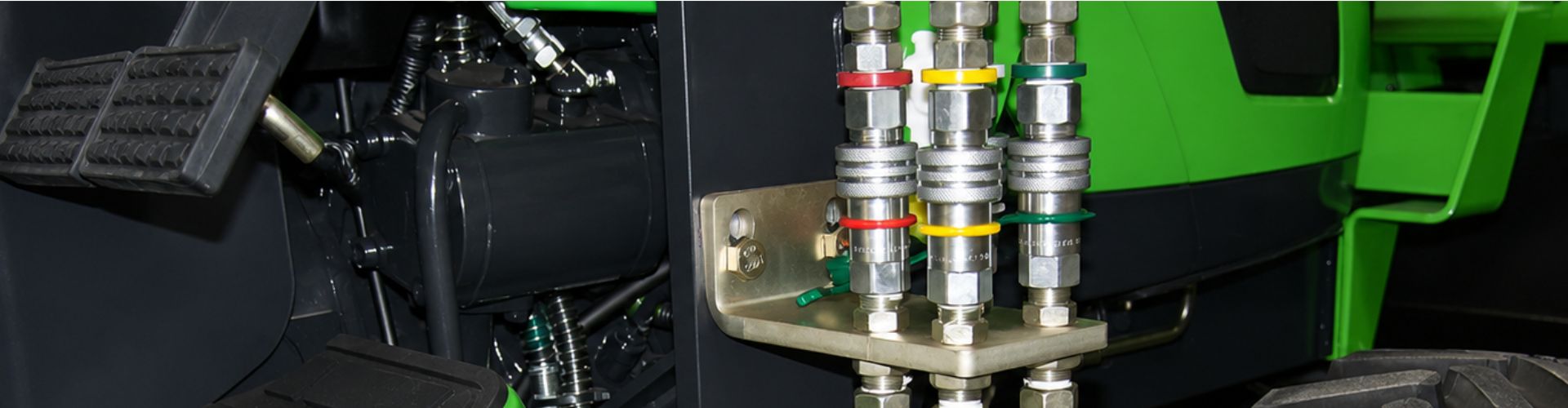
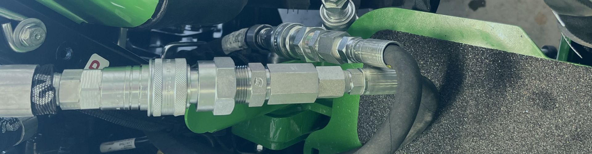
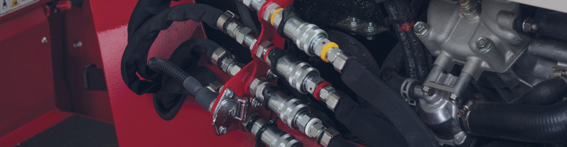
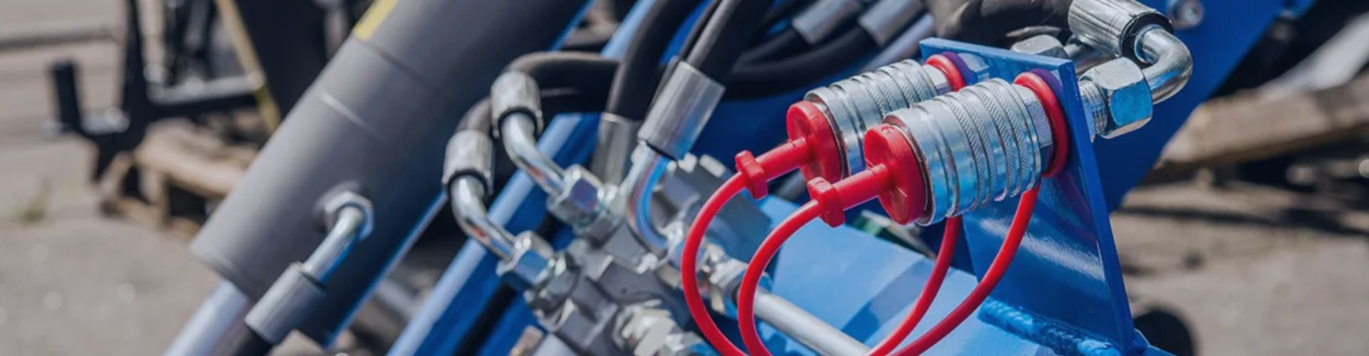
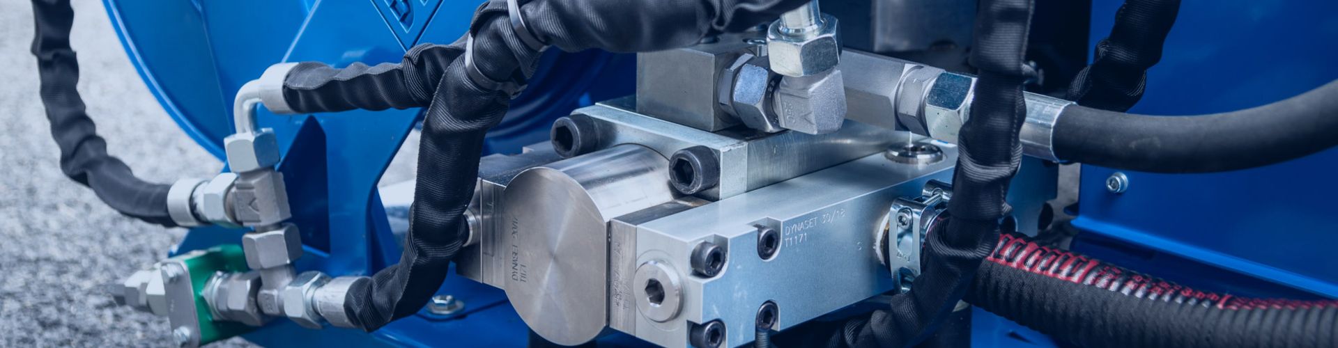
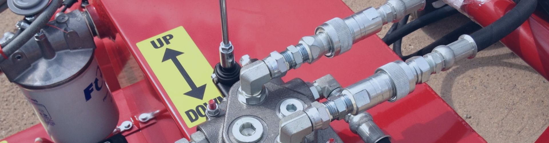
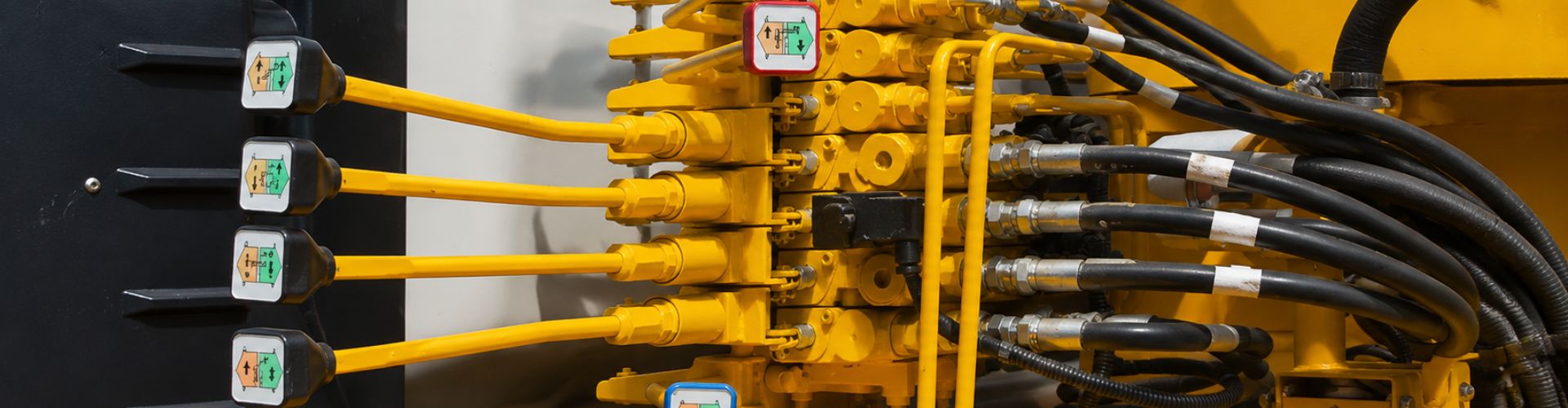
Quick Coupling vs Threaded Fitting Which is Right

Quick Coupling vs Threaded Fitting: Which is Right?

You need to connect hydraulic lines, but making the wrong choice leads to leaks, inefficiency, and costly downtime. It’s a decision that can impact your entire operation’s productivity.

Use threaded fittings for permanent, high-strength connections. Choose quick couplings for applications requiring frequent, fast connection and disconnection, like on attachments. This simple rule guides you to the right choice every time.

What is the Core Difference in How They Work?

You see two different fittings. They both connect hoses, but choosing the wrong one can cost you valuable time and money.

Threaded fittings, like JIC or ORFS, use wrenches to create a high-strength, permanent seal. Quick couplings use a sleeve and locking-ball mechanism for instant, tool-free connection, with internal valves to prevent fluid loss.

Hydraulic Quick connector Material Topa

The Mechanics of a Threaded Fitting

Threaded fittings achieve their seal through immense clamping force.

The Anatomy of a Quick Coupling

Quick couplings are engineered for speed and convenience. Their design is more complex, with multiple moving parts working together.

When Are Quick Couplings the Obvious Choice?

You’re constantly swapping hydraulic attachments. Wasting time with wrenches and cleaning up oil spills is killing your productivity.

Quick couplings are essential for any application requiring frequent connection and disconnection. They are perfect for agricultural implements, construction attachments, and mobile diagnostic equipment. Speed and convenience are their primary benefits.

valve Quick Coupling

Agricultural and Forestry Attachments

Think of a tractor. It needs to connect to a plow, a seeder, a baler, and a mower. Or a forestry machine swapping between a harvester head and a grapple. Using threaded fittings here would be a nightmare. Quick couplings allow for these changes to happen in seconds, without tools and with minimal fluid loss.

Construction Equipment Versatility

Excavators and skid steers are tool carriers. The value of the machine is its ability to use different attachments.

Quick couplings, especially spill-free flat-face models, are the only practical way to manage this rapid swapping of tools on a job site.

Diagnostic and Testing Points

Quick couplings aren’t just for heavy attachments. They also play a key role in system monitoring. By placing them at critical test points, maintenance crews can:

This avoids opening permanent lines, reducing downtime and the risk of contamination. A small investment in couplings translates into faster troubleshooting and safer maintenance.

When Should You Always Use Threaded Fittings?

Quick couplings are great for speed, but they’re not the answer to every problem. In many cases, threaded fittings are the safer, stronger, and more reliable choice. They’re designed for permanence and can withstand the harshest pressures, vibrations, and environments.

Permanent, High-Pressure Connections

Threaded fittings shine where a connection isn’t meant to come apart. Examples include:

In these cases, the system operates under constant high pressure. A threaded connection, tightened to the correct torque, provides the clamping force needed to maintain a leak-free seal day after day.

Topa metric hydraulic fitting various threads

Environments with Extreme Vibration

Machines like crushers, drilling rigs, or heavy mining equipment generate strong shock loads. Quick couplings could loosen or wear out here. Threaded fittings are better because:

Critical Safety Applications

When a leak could endanger workers or damage expensive equipment, threaded fittings are the obvious choice. For example:

These applications demand maximum security. Threaded fittings with either a flare or O-ring seal eliminate unnecessary risk.

Compact or Confined Installations

Quick couplings are bulky and add length to a line. Threaded fittings, on the other hand, fit neatly into tight assemblies. They are often the only practical option in:

How Do They Compare on Pressure Rating and Flow?

You chose a fitting, but now your hydraulic attachment feels sluggish. The wrong connection type is choking your system’s performance and wasting power.

Threaded fittings typically offer higher pressure ratings and less flow restriction. Quick couplings, because of their complex internal valves, introduce a pressure drop and often have a lower maximum working pressure than a similarly sized threaded fitting.

Hydraulic Adapters materials

Pressure Rating

Threaded Fittings

Quick Couplings

Flow Characteristics

Threaded Fittings

Quick Couplings

The Impact of Pressure Drop

Every component in a hydraulic system creates some restriction to flow, which results in a loss of pressure. The complex path fluid takes through a quick coupling’s valves creates a much higher pressure drop than the smooth, open path of a threaded fitting. This robs your attachment of power and generates waste heat. Sizing the quick coupling correctly for your system’s flow rate is critical to minimize this effect.

What Are the Interchangeability Standards?

You bought a new quick coupler, but it won’t connect to your existing equipment. Now your job is on hold, and your brand-new part is useless.

Threaded fittings use well-defined global standards (JIC, BSPP) that are usually interchangeable. Quick couplings have many different profiles (ISO A, ISO B, Flat Face) that are physically incompatible with each other. Verifying the profile is essential.

Hydraulic Quick coupler Manufacturer in China Topa

Common Quick Coupler Profiles

The Simplicity of Threaded Standards

Threaded fittings are much easier to manage. Global standards ensure near-universal interchangeability, meaning parts from different manufacturers will fit if they follow the same specification.

What is the Difference in Cost and Longevity?

Cost

Threaded Fittings

Quick Couplings

Longevity

Threaded Fittings

Quick Couplings

Conclusion

Choose correctly to maximize reliability and efficiency. Use permanent threaded fittings for the machine’s core system and select quick couplings for attachments and points that require frequent access.

At Topa, we know every minute of downtime means lost opportunities. That’s why we offer a complete range of hydraulic fittings, hoses, and quick couplings designed for reliability and fast delivery. All products are inspected 100% before shipment to guarantee performance in your toughest applications.

Now is the perfect time to place your order. By confirming your purchase early, you secure competitive pricing, shorter lead times, and priority in our production schedule. Whether you need standard parts or customized solutions with logo and packaging, our team is ready to support you.


FAQ

What materials are quick couplers and threaded fittings made from?

Most are made from carbon steel with zinc plating. For corrosive or marine environments, stainless steel or brass options are also available.

Do quick couplers and threaded fittings come in different sizes?

Yes. Standard sizes range from 1/8” to 2” depending on the series. Always match the fitting size to your hose and system flow requirements.

Are replacement seals available for quick couplers?

Yes. O-rings and valve seals can be replaced to extend service life. Using the correct material (NBR, Viton, EPDM) ensures compatibility with your hydraulic fluid.

Can threaded fittings and quick couplers handle different fluids?

Both can be used with hydraulic oil, water-glycol, and some synthetic fluids. Always check material compatibility before use.

Do these products meet international standards?

Yes. Threaded fittings are produced to SAE, ISO, DIN, or BSP standards. Quick couplers follow ISO 5675, ISO 7241-1 A/B, or ISO 16028 profiles for interchangeability.

What is the temperature range for quick couplers and threaded fittings?

Typically –20°C to +120°C with standard seals. For higher or lower temperatures, special seal materials like Viton or PTFE can be used.

How to Compare Flat Face vs Threaded Quick Couplers

How to Compare Flat Face vs Threaded Quick Couplers?

Hydraulic quick couplers allow fast, leak-free hose connections in demanding environments. Two common types dominate the market: flat face quick couplers and threaded quick couplers. Choosing the right one depends on application, pressure, and maintenance needs.

This guide explains the differences between flat face and threaded couplers, their advantages, disadvantages, and best uses. By the end, you will know how to select the right coupler for your hydraulic system.

What Are Flat Face Quick Couplers?

Flat face quick couplers are a type of hydraulic connector designed with smooth, flush mating surfaces. Unlike older designs with protruding valves, the flat faces press directly together, sealing the connection with an O-ring. This design minimizes fluid spillage and prevents air from entering the hydraulic system during connection or disconnection. They are widely used where system cleanliness and environmental safety are priorities.

Flat quick release hydraulic fitting

Features

Common Uses

What Are Threaded Quick Couplers?

Threaded quick couplers are hydraulic connectors that join by screwing the male and female halves together. Instead of a push-to-connect design, they use a threaded sleeve to lock the connection securely. This creates a tight, high-pressure seal that resists accidental disconnection, even in the harshest conditions.

Features

Common Uses

Key Differences: Flat Face vs Threaded Couplers

Sealing Method

Contamination Control

Flat Face Hydraulic Coupler install

Pressure Handling

Advantages and Disadvantages of Flat Face vs Threaded Quick Couplers

Flat Face Quick Couplers

Advantages

Disadvantages

Thread Connected Series quick coupling manufacturer

Threaded Quick Couplers

Advantages

Disadvantages

How to Choose the Right Quick Coupler

Consider System Pressure

Consider Operating Environment

Consider Maintenance Needs

Best Practices for Installation

Flat Face Couplers

Step 1: Prepare the Work Area

Ensure the hydraulic system is depressurized before starting. Clean the workbench or installation area to avoid dust or debris contaminating the couplers.

Step 2: Inspect Coupler Components

Check both male and female halves for scratches, dents, or corrosion. Inspect the O-ring for cracks, flattening, or hardness. Replace worn parts before installation.

Step 3: Clean the Flat Mating Surfaces

Use a lint-free cloth to wipe the flat faces. Remove dust, oil, or moisture that could compromise sealing. In dirty environments, use protective caps until installation.

Step 4: Align the Coupler Halves

Carefully align the male and female faces before connection. Misalignment can damage the O-ring or sealing surface. Hold the couplers straight to prevent cross-threading.

Step 5: Engage Threads by Hand

Start threading by hand to ensure smooth engagement. This prevents cross-thread damage. Do not use tools at this stage.

Step 6: Apply the Correct Torque

Use a calibrated torque wrench to tighten the connection. Follow the manufacturer’s torque chart for the correct value based on thread size and material. Apply torque gradually, not with sudden force.

Step 7: Verify Coupler Locking

Check that the locking mechanism (if included) is fully engaged. Ensure the connection feels secure and cannot be disconnected accidentally.

Step 8: Perform a Pressure Test

Run the hydraulic system at normal operating pressure. Inspect for leaks, seepage, or vibration-related loosening. For safety-critical systems, document the results in a maintenance log.

Step 9: Final Inspection and Maintenance Prep

Check hose alignment to ensure there is no twisting or bending stress on the coupler. Confirm that dust caps are available for future protection when the coupler is not connected.

collection of hydraulic quick couplings

Threaded Couplers

Step 1: Prepare the Equipment

Depressurize the hydraulic system completely before installation. Confirm that the work area is clean and free of dust, oil, and other contaminants that could interfere with the threads.

Step 2: Inspect Threads and Seals

Check both male and female coupler threads for signs of wear, corrosion, or deformation. Inspect the O-rings or backup seals for cracks, flattening, or cuts. Replace damaged components before assembly.

Step 3: Clean the Threads Thoroughly

Exposed threads often trap grit, dust, or dried oil. Use a soft brush or lint-free cloth to clean them. For heavy contamination, a suitable cleaning solvent may be used. This prevents debris from grinding into the connection.

Step 4: Align the Coupler Halves

Hold the couplers in straight alignment before threading. Misalignment can cross-thread or damage the sealing surfaces. Always engage threads smoothly to avoid forced starts.

Step 5: Hand-Tighten First

Begin threading the male and female halves together by hand. This ensures correct thread engagement and prevents cross-threading, which is a common cause of damage in threaded couplers.

Step 6: Apply Torque with a Wrench

Switch to a calibrated torque wrench once hand-tightened. Tighten the sleeve gradually, applying steady, even force. Follow the manufacturer’s torque chart for the correct value based on size and material.

Step 7: Avoid Over-Torquing

Stop tightening once the specified torque is reached. Applying extra force can strip threads, distort the sleeve, or permanently deform the coupler body.

Step 8: Lock and Verify

Ensure the threaded sleeve is fully seated and locked. Check for any gaps between the coupler halves. A properly installed threaded coupler should feel secure without excessive force.

Step 9: Perform a Pressure Test

Pressurize the hydraulic system to operating conditions. Inspect the connection for leaks, vibration loosening, or abnormal noises. Document the results for quality assurance or maintenance records.

Hydraulic Quick coupler Manufacturer in China Topa

Maintenance Tips for Both Types

Inspect couplers regularly for wear and leaks

Frequent inspections are essential to prevent unexpected failures. Look for oil seepage, cracks on the body, worn threads, or damaged sealing surfaces. Early detection allows you to repair or replace couplers before they cause system downtime.

Replace O-rings showing cracks or deformation

O-rings provide the primary sealing function in both flat face and threaded couplers. Over time, they can harden, flatten, or crack due to heat, pressure cycles, or chemical exposure. A damaged O-ring cannot hold pressure effectively, leading to leaks.

Use only manufacturer-recommended torque values

Incorrect torque is a major cause of premature coupler failure. Under-torque results in leaks, while over-torque can strip threads and crush seals. Each manufacturer provides a torque chart for their specific coupler designs. Use a calibrated torque wrench to ensure accuracy and consistency.

Keep spare couplers available for quick replacement

Even with proper care, couplers eventually wear out. Having spares in stock ensures that damaged units can be replaced immediately, reducing downtime. This is especially important for industries like construction, agriculture, and mining, where delays are costly. Store spare couplers in clean, sealed containers or with protective caps to keep them free from dirt and moisture until needed.

Conclusion

Selecting the right coupler type depends on your system pressure, operating environment, and maintenance needs. By choosing correctly, you reduce downtime, extend equipment life, and ensure safe, efficient hydraulic performance.

Ready to Place Your Order? At Topa, we manufacture and supply both flat face and threaded hydraulic quick couplers, tested to meet international standards.


FAQ

What is the main difference between flat face and threaded quick couplers?

Flat face couplers focus on cleanliness and spill control, while threaded couplers provide higher strength and pressure resistance.

Which coupler type is better for high-pressure applications?

Threaded quick couplers are safer for extreme high-pressure and vibration-heavy environments like oilfield or mining.

Why are flat face couplers popular in agriculture and construction?

They reduce oil spillage, are easy to clean, and allow fast attachment changes without tools.

Do both coupler types require torque control during installation?

Yes. Incorrect torque may cause leaks or thread damage. Always follow the manufacturer’s torque chart.

What maintenance steps help extend coupler life?

Inspect regularly, replace worn O-rings, clean sealing surfaces, and keep spare couplers ready for replacement.

Can I use flat face and threaded couplers in the same hydraulic system?

It’s not recommended. Mixing types can create compatibility issues. Stick with one type for consistency and safety.

How to Avoid Overtightening Reusable Fittings

How to Avoid Overtightening Reusable Fittings?

You just spent an hour in the field replacing a hydraulic hose. You tighten the new reusable fitting with all your strength, only to start the engine and see a steady drip.

To avoid overtightening, use the “flats from wrench resistance” (FFWR) method. Tighten the fitting by hand until it’s snug, then use a wrench to turn it a specific number of full flats—usually between two and four—as specified by the manufacturer.

Why Overtightening Happens

Common Causes

Impact of Overtightening

What Are the Signs of an Overtightened Fitting?

You’ve installed the fitting, but you have a bad feeling about it. How can you tell if you’ve done permanent damage without even starting the machine?

The most obvious signs of an overtightened fitting are visible cracks in the outer socket or stripped threads on the nipple. Leaks that appear under pressure, especially near the fitting, are also a clear giveaway that the internal seal has been compromised by excessive force.

rust Reusable Hydraulic Hose Fittings Topa

Immediate and Visible Damage

Severe overtightening often leaves clear, physical signs that can be spotted without disassembly:

Leaks Under Pressure or Vibration

Not all damage from overtightening is visible during installation. Some problems only appear once the system is running:

Inspecting a Disassembled Fitting

If you suspect overtightening, disassemble the fitting and check both the hose and the fitting components carefully:

Inspection Checklist for Overtightening:

How Do You Achieve the Perfect Tightness Every Time?

You want a reliable, leak-free connection on the first try. What is the professional method that guarantees you never under-tighten or over-tighten a reusable fitting again?

The perfect tightness is achieved by following the manufacturer’s assembly instructions exactly. This involves proper hose preparation, lubrication, and using the “flats from wrench resistance” (FFWR) method for the final, precise tightening sequence.

install reusable Hydraulic Fitting

The Full Assembly Process, Step-by-Step

Step 1: Cut the Hose Cleanly

Step 2: Insert the Nipple

Step 3: Thread the Socket

Step 4: Tighten with a Torque Wrench

The “Flats From Wrench Resistance” (FFWR) Method

The Flats From Wrench Resistance (FFWR) method is one of the most reliable techniques for correctly tightening reusable fittings in the field. Unlike guessing by “feel,” this method provides a repeatable, measurable way to achieve the right clamping force without overtightening.

How the Method Works

A standard hex fitting has six flat sides, often referred to as “flats.” The FFWR method uses these flats as a reference for how far the fitting should be rotated after reaching finger-tight contact. Each flat represents 1/6 of a turn, making it easy to measure tightening angle without special tools.

Step-by-Step Process

Why FFWR Is Accurate

Common Mistakes to Avoid

1. Overconfidence in Hand Tightening

Many technicians trust their experience and believe they can “feel” the correct tightness. However, this method is unreliable:

2. Ignoring Thread Condition

Threads are critical to forming a secure connection, yet they are often overlooked.

reusable Hydraulic Hose Assemblies

3. Skipping the Pressure Test

Even the best installation can fail if the connection isn’t tested under real conditions.

Maintenance Tips for Reusable Fittings

Perform Regular Inspections

Keep Threads and Sealing Surfaces Clean

Replace Worn or Damaged Components

Apply Correct Torque Every Time

Pressure-Test After Installation

Stock Spare Fittings and O-Rings

Conclusion

Only by adhering to proper operating procedures—using torque wrenches or FFWR methods, maintaining clean threads, replacing worn components, and always performing pressure tests—can you ensure joints are safe, reliable, and durable.

At Topa, we provide high-quality, reusable hydraulic fittngs to help you avoid over-tightening issues.

Get a free quote today. Choose Topa as your partner to ensure smooth operation of your hydraulic systems with durable joints and professional service.


FAQ

What happens if I overtighten a reusable fitting?

Overtightening can strip threads, crush O-rings, and damage hoses, leading to leaks and premature failure.

How can I prevent overtightening during installation?

Always use a calibrated torque wrench or the Flats From Wrench Resistance (FFWR) method instead of relying on hand feel.

Do all reusable fittings require the same torque value?

No. Torque varies by hose size, thread type, and fitting design. Always check the manufacturer’s torque chart.

What are the visible signs of overtightening?

Cracked sockets, flattened threads, bulged hose ends, or leaks under pressure are clear signs of damage.

Can I reuse a fitting after it has been overtightened?

No. Once threads or sealing surfaces are damaged, the fitting should be discarded to ensure safety.

Why is pressure testing important after installation?

A pressure test confirms that the fitting seals properly under real operating conditions and prevents unexpected leaks in service.

How Tight Should You Torque a Quick Coupler

How Tight Should You Torque a Quick Coupler?

Are you tired of quick couplers that weep or leak after installation? A connection that’s too loose can vibrate apart, while one that’s too tight can crack the fitting, causing costly fluid loss and downtime.

The correct torque for a hydraulic quick coupler depends on its thread type, size, and material. Always consult the manufacturer’s torque chart for the specific value. This ensures a durable, leak-free seal without causing damage to the fitting’s threads or O-rings.

What Is Torque in Hydraulic Couplers?

Definition of Torque

Torque is the twisting force used to tighten a threaded connection. In hydraulic quick couplers, torque ensures the male and female threads engage securely without overstressing the parts. It is typically measured in Newton-meters (Nm) or foot-pounds (ft-lb) using a calibrated torque wrench. Applying the correct torque value provides the right clamping force to hold the coupler in place, while still protecting the threads, O-rings, and sealing surfaces from damage.

Why Torque Matters

Types of Hydraulic Quick Couplers

Flat Face Couplers

Flat face couplers are designed to minimize fluid loss during connection and disconnection. Their flush, flat mating surfaces prevent dirt from entering the hydraulic system and make cleaning easy. Because the sealing surface is broad and smooth, they require precise torque to achieve a proper seal. Even slight under- or over-tightening can affect performance.

Hydraulic Quick coupling Topa factory in China

Poppet Couplers

Poppet-style couplers use a spring-loaded poppet valve that opens when the coupler halves connect. This design allows quick engagement and provides reliable sealing, though a small amount of fluid loss may occur during disconnection. They are durable, versatile, and simple to use, making them popular in general hydraulic applications, mobile equipment, and utility machinery.

Screw-to-Connect Couplers

Screw-to-connect couplers are built for high-pressure and high-vibration environments. Instead of a push-pull mechanism, they use a threaded sleeve that must be screwed together to connect. This design withstands heavy loads, impulse cycles, and extreme working conditions. Because of the threaded locking mechanism, they require higher torque values to ensure a secure and leak-free fit.

How to Torque Hydraulic Quick Couplers Correctly

Tools Needed

Install Hydraulic Quick Coupler

Step-by-Step Guide

Best Practices for Correct Torque

Before Installation

During Installation

After Installation

Common Mistakes When Tightening Quick Couplers

Over-Tightening

rust Quick Coupler Maintenance

Under-Tightening

Using the Wrong Tools

Ignoring Manufacturer Guidelines

Where Can You Find the Right Torque Values?

Can’t locate the installation specs for your new hydraulic quick coupler? Tightening by guesswork is risky—it can cause leaks, damaged fittings, or even equipment failure at the worst possible time.

How to Read a Torque Chart

Torque charts are straightforward once you know the layout. Each table is organized by:

To use a chart, simply match your fitting size and thread type with the listed torque value. Then, apply it with a calibrated torque wrench in your preferred unit of measure.

The Impact of Lubrication on Torque

If you apply a “dry” torque value to a lubricated fitting, you will almost certainly over-tighten and risk damaging the part. Always check the chart notes to confirm which condition applies.

When You Can’t Find the Chart

If the manufacturer’s torque chart isn’t available, the best solution is to contact your supplier directly. Never guess.

In urgent cases, you may use industry-standard torque charts from major hydraulic fitting standards (such as JIC or NPT). While these can serve as general guidelines, they don’t account for proprietary designs, coatings, or materials that may alter torque requirements.

Bottom line: The manufacturer’s specification is always the most reliable source. Using it ensures safe, leak-free, and long-lasting hydraulic connections.

Conclusion

Properly installing a hydraulic quick coupler is simple: use the manufacturer’s chart, understand your thread type, and follow the correct procedure with a calibrated torque wrench for a guaranteed result.

Looking for reliable hydraulic quick couplers with guaranteed performance? Topa offers both flat face and poppet designs, tested for durability and supported with complete torque charts. Whether you need small batches for repair work or bulk orders for production lines, we deliver high-quality products at competitive prices.


FAQ

Why is correct torque important for hydraulic quick couplers?

Correct torque prevents leaks, protects threads and seals, and ensures safe, long-lasting operation.

What tool should I use to tighten a quick coupler?

Always use a calibrated torque wrench. Avoid pipe wrenches, as they can damage the coupler.

Do all couplers require the same torque value?

No. Torque values depend on coupler type, thread size, and material. Always check the manufacturer’s chart.

Can over-tightening cause damage?

Yes. Too much torque can strip threads, crush seals, and make disassembly difficult.

What happens if a coupler is under-tightened?

Under-tightening leads to leaks, reduced pressure capacity, and loosening under vibration.

Should I use thread sealant on all quick couplers?

No. Use sealant only on tapered threads like NPT or BSPT. For ORFS, JIC, or flat face designs, sealing is achieved mechanically, and sealant is not needed.

What’s Better for You Flat Face or Poppet Couplers

What’s Better for You: Flat Face or Poppet Couplers?

Tired of messy hydraulic fluid spills or connection failures? Choosing the wrong quick coupler costs you time and money, and it can even damage your equipment. This choice matters.

The right hydraulic quick coupler depends entirely on your application’s needs. Flat face couplers are best for clean environments to prevent spills and contamination. Poppet couplers are a durable, cost-effective choice for general-purpose applications where minor fluid loss is acceptable.

What Exactly is a Flat Face Coupler?

Are you working in an environment where even a small oil leak is a big problem? Contamination and spills can shut down a job site and lead to costly cleanups.

A flat face coupler is a type of hydraulic quick connect designed for zero leakage during connection and disconnection. Its flush mating surfaces are easy to clean, preventing dirt from entering the hydraulic system and oil from contaminating the environment. They are the modern standard for sensitive applications.

flat face connect Quick Coupling

Flat face couplers are a marvel of simple, effective engineering. When I explain it to new buyers, I always focus on the “no-spill” design. It’s the most important feature.

How Does It Work?

Both the male and female halves of a flat face coupler feature smooth, flush-mounted valve surfaces that align perfectly when disconnected. This design eliminates cavities where oil could leak or where dirt could collect.

When the two halves are pushed together, the internal valves retract in a synchronized motion, allowing hydraulic fluid to flow freely through the connection. Because the valves retract only after the faces are fully sealed against each other, the system avoids the sudden spray or drips that are common with older coupler designs.

During disconnection, the process works in reverse. The valves close before the couplers separate, instantly sealing off both sides of the line. This means that virtually no oil escapes into the environment, and no air, dust, or moisture can enter the hydraulic system.

Key Advantages You Should Know

The benefits go beyond just being clean. I remember a customer in the construction industry who switched to flat face couplers on all his excavators. He told me his maintenance costs dropped because his hydraulic systems were running much cleaner.

Applications of Flat Face Quick Couplers

Construction Machinery

Excavators, skid steers, and loaders for hydraulic attachments (buckets, breakers, augers).

Agricultural Equipment

Tractors and harvesters for implements like plows, seeders, and hydraulic-driven sprayers.

Forestry Machinery

Used on harvesters, forwarders, and log splitters where hydraulic tools are swapped often.

Mining & Heavy Equipment

Hydraulic power units, drills, and underground machinery.

Oil & Gas / Industrial Applications

Hydraulic power packs, subsea tools, and offshore rigs.

Material Handling

Forklifts, cranes, and attachments needing quick hydraulic connections.

What is a Poppet Coupler?

Do you need a reliable, proven, and budget-friendly connection for your hydraulic tools? For many, the traditional poppet coupler has been the go-to solution for decades.

A poppet coupler is a common style of hydraulic quick connect that uses a ball or poppet-style valve to control flow. It’s a robust and cost-effective design that has been a workhorse in industries around the world for many years.

Poppet-Type Quick Couplings

The poppet coupler is a classic for a reason. Here in our factory, we’ve manufactured these for years, and their simple, strong design is valued by many of our long-term clients, especially those in demanding environments like farming in Africa or mobile equipment maintenance in South America.

The Mechanics of a Poppet Valve

When a poppet coupler is disconnected, a spring-loaded mechanism keeps a small ball or cone-shaped “poppet” tightly pressed against its seat. This creates a seal that blocks hydraulic fluid from leaking out of the system while the coupler is not in use. The spring ensures that the poppet remains in position, even if the hose or equipment is under residual pressure.

During connection, the process is straightforward but effective. As the male and female halves come together, a probe on the male half pushes directly against the poppet, forcing it off the seat. This action opens the fluid passage and allows hydraulic oil to flow freely through the system. Because the design minimizes internal restrictions, poppet couplers can deliver very high flow rates, making them well-suited for equipment that requires large volumes of hydraulic fluid.

Main Benefits to Consider

Where It’s Used Most

Poppet couplers are extremely common in agriculture, general industrial use, and on older mobile equipment.

Agriculture

Tractors, combines, and sprayers.

Construction Equipment

Backhoes, loaders, and small excavators.

Industrial Hydraulics

Hydraulic presses, test stands, and machine tools.

Forestry & Logging

Used in sawmills, log splitters, and skidders.

Oil & Gas

Hydraulic power units and drilling rigs.

Transportation / Mobile Equipment

Truck-mounted hydraulic systems (dump trucks, cranes, tow trucks).

How Do They Compare Head-to-Head?

Feeling stuck choosing between modern cleanliness and traditional reliability? This direct comparison will clear things up and help you decide which is truly better for your work.

Flat face couplers excel in preventing spills and contamination, making them ideal for sensitive environments. Poppet couplers are more budget-friendly and offer robust, high-flow performance for general-purpose use where minor drips are not a major concern. The best choice depends on your priority.

poppet valve vs ball-locking quick coupling

Spillage and System Contamination

This is the biggest difference.

Pressure and Flow Dynamics

Performance under pressure is key.

The True Cost: Price vs. Longevity

Your budget is always a factor.

Here is a simple breakdown:

Which Applications Demand a Specific Coupler?

Worried you’ll buy the wrong coupler for your machine? Matching the coupler to the job and environment is critical for safety, efficiency, and avoiding costly mistakes.

Use flat face couplers for high-end construction, food processing, or any job where spills are unacceptable. Stick with poppet couplers for general agriculture, older industrial machinery, and applications where budget and interchangeability with existing equipment are your primary concerns.

Quick Coupler Workspce

We’ve shipped couplers to nearly every type of industry you can imagine. This experience has given us clear insights into where each type performs best. Let me share a couple of real-world examples that illustrate this perfectly.

Case Study: A Construction Firm in the USA

I remember working with a procurement manager, for a large construction company in the US. They were using poppet couplers on their skid steer loaders. They had a recurring problem: when operators changed attachments like buckets and breakers, hydraulic fluid would drip onto finished concrete and asphalt, leaving ugly stains. This led to customer complaints and costly pressure-washing services. We recommended they switch to our ISO 16028 flat face couplers. The problem disappeared overnight. The slightly higher initial cost was quickly recovered by eliminating cleanup costs and improving their professional image.

When to Stick with Poppet Couplers

On the other hand, I spoke with a small farm owner in the Philippines a few months ago. He runs older tractors and uses several different attachments. His priority was simple: he needed a reliable coupler that was inexpensive and compatible with his existing equipment. For his work in the open field, a few drops of oil were not a concern. He needed durability and value. We supplied him with standard poppet couplers, and he was extremely happy. It was the right tool for his job and his budget.

Industry-Specific Recommendations

To make it even simpler, here is a list of industries and our typical recommendation:

Conclusion

Ultimately, the right coupler is the one that fits your application, environment, and budget. Flat face offers modern cleanliness, while poppet provides traditional, cost-effective reliability.

At Topa, we offer high-quality hydraulic quick couplings in both flat-face and spring-valve designs, engineered for construction, agricultural, and industrial systems to ensure reliable, leak-free performance. Contact Topa today for a quick quote.


FAQ

What is the main difference between flat face and poppet couplers?

Flat face couplers prevent fluid spills and contamination, while poppet couplers are more cost-effective but allow minor leakage.

Which coupler is better for high-pressure systems?

Flat face couplers are designed for modern high-pressure applications and can often be connected under residual pressure.

Are poppet couplers still widely used?

Yes, they remain popular in agriculture, forestry, and older equipment due to durability, affordability, and wide availability.

Do flat face couplers cost more?

The initial price is higher, but they reduce cleanup costs, fluid loss, and equipment wear—lowering long-term expenses.

Can I interchange flat face and poppet couplers?

No, they use different designs and standards. Always match coupler types for compatibility

Which industries typically choose flat face couplers?

Construction, manufacturing, and food processing industries prefer flat face for clean, leak-free operations.

What Quick Coupler Is Best for Your Hydraulic Power Unit

What Quick Coupler Is Best for Your Hydraulic Power Unit?

Your HPU is the heart of your operation, but the wrong couplers are strangling its power. This leads to frustratingly slow tool performance, wasted energy, and dangerous levels of heat buildup.

The right quick coupler for a hydraulic power unit (HPU) must match its flow rate (GPM), exceed its maximum pressure rating, and suit the application. Prioritize high-flow designs like flat face or screw-to-connect styles and consider features like pressure-release mechanisms for safe, efficient operation.

Quick Coupler Workspce

A hydraulic power unit represents a significant investment in power and productivity. It is the central nervous system of your hydraulic equipment, generating the flow and pressure needed to run everything from rescue tools to massive industrial presses. But this power is useless if it cannot be delivered efficiently to the tool. The quick couplers you choose are the gateways to this power. A poor choice creates a bottleneck that not only hinders performance but can also jeopardize the health and longevity of the entire HPU. As a global supplier of hydraulic components, we help our clients look beyond simple thread sizes. We guide them through the critical technical specifications to ensure that every connection enhances, rather than compromises, their system’s power.

Why is Flow Rate the Most Critical Factor for an HPU Coupler?

Your HPU has a high GPM rating, but the attached tool moves sluggishly. This performance gap points directly to a bottleneck in the system, turning expensive hydraulic power into useless heat.

An undersized coupler causes a severe pressure drop as the HPU’s flow is forced through a small opening. This converts hydraulic energy into heat, starving the tool of power and forcing the HPU’s pump to work harder.

Quick Coupler for Hydraulic Power Unit

A Bottleneck Turns Power into Heat

Think of your HPU as a powerful engine. The quick coupler is the transmission that delivers that power. If the transmission is too small, the engine will strain, overheat, and fail to deliver its full potential. In hydraulics, this strain is measured as pressure drop. Every HPU has a rated flow in Gallons Per Minute (GPM) or Liters Per Minute (LPM). The quick coupler must have an adequate Flow Coefficient (Cv) to allow this flow to pass through with minimal restriction.

When the HPU’s flow rate exceeds the coupler’s capacity, the fluid velocity inside the coupler skyrockets. This creates massive turbulence and friction, and the energy lost is converted directly into heat.

The Cost of Inefficiency

This heat is the number one enemy of a hydraulic system. It degrades the oil, damages seals, and can cause the HPU to shut down on a thermal trip. A high pressure drop also means that the pressure available at the tool is significantly lower than the pressure generated by the HPU. A 100 PSI drop at the coupler is 100 PSI that is simply not available to do work. Choosing a coupler with a high Cv value that is properly sized for the HPU’s flow rate is the most important step in ensuring that the power you are paying for is the power you are getting at the tool.

Which Coupler Type is Best for HPU Applications?

You are constantly dealing with messy fluid spills and fear dirt getting into your HPU. The standard couplers you use are a known weak point, compromising both safety and system cleanliness.

Flat face (ISO 16028) couplers are excellent for general HPU use due to their non-spill design and easy cleaning. For high-impulse or extreme-pressure applications, screw-to-connect couplers offer the most secure connection.

Hydraulic Quick coupler Manufacturer in China Topa

Matching the Design to the Demand

Not all quick couplers are built the same. The internal valve design dramatically affects their performance, cleanliness, and suitability for different HPU jobs. Choosing the right type is key to reliability.

Poppet Style (ISO 7241 A/B)

These are the most common and economical couplers. However, their poppet valve design allows for significant fluid spillage upon disconnection and creates a cavity that traps dirt, which can then be injected into the HPU. While acceptable for some applications, they are not ideal for systems where cleanliness and minimal spillage are priorities.

Flat Face Style (ISO 16028)

This design is a major upgrade. The mating surfaces are flush, allowing them to be wiped perfectly clean before connection. Upon disconnection, the valves close right at the face, resulting in near-zero fluid spillage. This makes them the superior choice for most HPU applications, drastically reducing contamination risk and keeping the work area clean and safe. They also typically offer better flow characteristics than poppet styles of the same size.

Screw-to-Connect Style (ISO 14541)

When the HPU powers high-impulse tools like hydraulic breakers or high-tonnage jacks, screw-to-connect couplers are the best option. The threaded sleeve provides a rock-solid mechanical connection that cannot be accidentally disconnected and is highly resistant to the pressure spikes (impulses) and vibration that can damage other coupler types.

How Do You Deal with Trapped Pressure When Connecting to an HPU?

The hose simply will not connect to the HPU coupler. The immense effort required to force the connection risks damaging the coupler and is a major source of frustration and downtime.

Trapped pressure makes connection very difficult. The best solution is to use quick couplers specifically designed to connect under pressure. These have integrated valves or sleeves that safely bleed off the pressure during connection.

Quick Couplers for Your Ag Machinery

The Trapped Pressure Problem

This is one of the most common problems in mobile hydraulics. A hydraulic hose left disconnected in the sun can experience a huge increase in internal pressure due to thermal expansion of the oil. This trapped pressure can easily reach several hundred or even thousands of PSI, making it physically impossible to push the male tip into the female coupler against that force. The traditional, unsafe solution is to crack open a fitting to bleed the pressure, spilling oil and creating a hazard.

A far better solution is to choose a coupler built to handle this.

When we consult with clients who operate HPUs in outdoor environments, we always highlight the availability of these connect-under-pressure solutions. They are a crucial feature for improving operator safety, reducing downtime, and preventing damage to equipment.

Can the Right Coupler Really Protect Your HPU from Contamination?

A tiny particle of dirt can destroy a multi-thousand-dollar HPU pump. You know that cleanliness is key, but the connection point itself seems like a major weak spot for ingression.

Yes, absolutely. A flat face (ISO 16028) coupler is a frontline defense against contamination. Its flush, non-spill design allows it to be wiped perfectly clean, preventing the injection of dirt into the HPU’s sensitive hydraulic system.

Designing for Cleanliness

Hydraulic contamination is the leading cause of component failure. Over 75% of hydraulic system failures can be traced back to contaminants in the fluid. While filtration systems are essential, preventing dirt from entering in the first place is a far more effective strategy. The quick coupler is the most common entry point for dirt.

The Flaw of the Poppet Design

A traditional poppet-style coupler has a recessed cavity around the valve. When disconnected, this cavity inevitably collects dust, grit, and moisture. Wiping it with a rag is ineffective, as the dirt is pushed deeper into the recess. The moment you connect this coupler, the incoming rush of hydraulic fluid flushes all that trapped grime directly into the HPU’s reservoir, where it can wreak havoc on pumps, valves, and seals.

The Superiority of the Flat Face Design

The flat face coupler was engineered specifically to solve this problem. Because the mating surfaces are completely flush when disconnected, there are no cavities to trap dirt. A simple wipe with a clean cloth is all that is needed to ensure a sterile connection surface. Furthermore, the non-spill design means that no sticky residue of oil is left on the coupler to attract more dust. Investing in flat face couplers for an HPU is one of the most cost-effective reliability upgrades you can make. It is a small price to pay to protect a very expensive asset.

Do Pressure and Return Lines on an HPU Need Different Couplers?

You have always used the same model of quick coupler for both the pressure and return lines. This seems logical, but it may be causing unseen problems like sluggish performance or leaking cylinder seals.

Yes, they have different demands. The pressure line needs a coupler rated for high pressure and impulses. The return line coupler needs an exceptionally high flow capacity (low pressure drop) to prevent back-pressure. Using different sizes is also a good safety practice.

quick coupler diagrame

A Tale of Two Lines

While they work together, the pressure (P) line and the tank/return (T) line perform very different functions, and their couplers should be chosen accordingly. Mistaking their requirements is a common design flaw.

The Pressure Line’s Job

The pressure line coupler has the tough job. It must safely contain the HPU’s maximum system pressure, which can be 3000 PSI, 5000 PSI, or even higher. It must also withstand the intense pressure spikes, or impulses, generated by the rapid cycling of valves and hydraulic tools. Here, strength and pressure rating are the top priorities.

The Return Line’s Job

The return line coupler has a different primary goal: get the oil back to the tank with as little restriction as possible. Any significant pressure drop in the return line creates back-pressure. This back-pressure works against the entire system. It can cause cylinder rod seals to fail, slow down actuator speeds, and generate unwanted heat. For the return line, you should select the largest coupler possible with the highest Cv value you can find to ensure the return path is free-flowing. Its pressure rating is less critical (as long as it meets minimal system requirements), but its flow capacity is paramount. Many engineers oversize the return line coupler for this very reason. It is also best practice to use different sizes for the P and T lines (e.g., 1/2″ for pressure, 3/4″ for return) to make it physically impossible to connect them incorrectly.

What Role Do Materials and Plating Play in an HPU Coupler’s Lifespan?

The couplers on your HPU are showing signs of rust after just one season of use. This corrosion looks bad, but it also threatens to seize the coupler and contaminate the hydraulic system.

The material and plating are crucial for durability. Standard couplers are carbon steel with zinc plating to resist rust. For wet or corrosive environments, a superior plating like Zinc-Nickel or a full 316 stainless steel body is necessary.

A Shield Against the Elements

A quick coupler’s body is its first line of defense against the operating environment. While the internal mechanics are vital for performance, the external material determines its lifespan in the face of moisture, salt, and chemicals.

The Standard: Plated Carbon Steel

Most hydraulic couplers are made from high-strength carbon steel. This provides excellent pressure containment but will rust very quickly if left unprotected. To prevent this, manufacturers apply a protective plating. Standard Zinc plating with a clear trivalent chromate (Cr3+) passivate is common. It offers basic protection, often rated for around 72-96 hours in a salt spray test before showing significant rust.

High-Performance Plating: Zinc-Nickel

For HPUs used outdoors, on marine equipment, or in winter conditions where road salt is present, a standard plating is not enough. We strongly recommend upgrading to a Zinc-Nickel alloy plating. This advanced finish provides a much tougher barrier against corrosion, often lasting over 700 hours in a salt spray test. This preserves the coupler’s functionality and professional appearance for years.

The Ultimate Solution: Stainless Steel

For the most demanding environments, such as chemical plants, offshore oil rigs, or food processing applications, 316 stainless steel is the best choice. While more expensive, stainless steel offers complete resistance to rust and superior resistance to a wide range of chemicals. It eliminates any risk of plating flaking off and contaminating the system, providing the ultimate in longevity and peace of mind.

Conclusion

Selecting the right quick coupler for your HPU is a critical decision. It requires a balanced consideration of flow rate, pressure, coupler type, material, and specialized features to ensure maximum safety and performance.

At Topa, we specialize in helping customers navigate these choices. We provide a vast range of high-performance quick couplers—from certified flat face to robust screw-to-connect models—in the materials and platings your application demands. Our expert team can help you select the perfect component to unleash the full power of your hydraulic power unit. Contact us today to ensure your connections are as strong as your system.


FAQ

What type of quick coupler is best for a hydraulic power unit (HPU)?

Flat face quick couplers are best because they minimize fluid loss, prevent contamination, and handle high flow efficiently.

Why is flow rate important when selecting an HPU coupler?

The coupler must match the HPU’s flow rate; if it’s too small, it causes pressure drops, heat buildup, and power loss.

Which coupler type suits high-pressure or impulse applications?

Screw-to-connect couplers are ideal since they create a strong, leak-free connection that withstands pressure spikes and vibration.

How can I connect hoses to an HPU under trapped pressure?

Use couplers with built-in pressure-release valves or screw-to-connect designs that safely vent internal pressure during connection.

Do pressure and return lines need different couplers?

Yes. The pressure line requires high-pressure rated couplers, while the return line needs larger, high-flow couplers to reduce back-pressure.

What materials offer the best corrosion resistance for HPU couplers?

Zinc-Nickel plated or 316 stainless steel couplers provide superior rust protection and long-term durability in harsh environments.

Is Your Quick Coupling Hurting System Performance

Is Your Quick Coupling Hurting System Performance?

Selecting the right quick coupling seems simple, but a poor choice can starve your system. This creates heat, wastes energy, and makes powerful machinery feel sluggish and unresponsive.

The key is understanding flow rate (GPM/LPM) and the coupling’s Flow Coefficient (Cv). A high Cv value indicates less internal restriction, allowing your target flow rate to pass through with minimal pressure loss and heat generation.

quick Coupling machine drawing

In hydraulic systems, power is a function of pressure and flow. The pump generates this power, but every component in the circuit consumes a portion of it. While we focus on pumps, motors, and cylinders, the humble quick coupling is often an overlooked source of significant power loss. A poorly selected coupling acts like a bottleneck, forcing the entire system to work harder to achieve the desired output. For engineers, maintenance managers, and business owners, understanding the relationship between flow rate, pressure drop, and the Cv rating is not just an academic exercise.

What Exactly Is Hydraulic Flow Rate?

You know your pump is rated for a certain flow, but the machine’s attachments move slowly. This frustrating gap between a component’s potential and its actual performance points to a restriction.

Flow rate is the volume of fluid that passes a specific point in a circuit over a set period. It is typically measured in Gallons Per Minute (GPM) or Liters Per Minute (LPM).

The Lifeblood of the System

Hydraulic flow rate, generated by the pump, is what makes things happen in a hydraulic system. It directly dictates the speed of actuators; more flow equals faster cylinder extension or higher motor RPM. Understanding flow is about more than just a single number, however. It involves a concept called flow velocity—the speed at which the fluid is traveling through the hose or tube. For a given flow rate (e.g., 20 GPM), the velocity of the fluid will be much higher in a small-diameter hose than in a large-diameter hose.

This relationship is critical because high fluid velocity leads to two negative outcomes: turbulence and increased friction.

This is why selecting the correct hose inner diameter (ID) for a system’s flow rate is the first step in efficient design. A quick coupling must then be selected to match this efficiently. An undersized coupler creates a sudden, drastic increase in velocity right at the connection point, creating a major source of turbulence and energy loss.

What Does the Cv Value Really Mean?

You see a “Cv Value” on a coupling’s technical data sheet, but it’s just a number. It is difficult to translate this abstract rating into a real-world performance advantage or disadvantage.

The Cv (Flow Coefficient) is a standardized measure of a valve’s or fitting’s efficiency. A higher Cv value means the component has less internal restriction and can pass more fluid with less energy loss.

flat face connect Quick Coupling

Quantifying Efficiency

The Cv value is the single most important metric for comparing the hydraulic efficiency of different quick couplings. It is an empirically derived, unitless number that represents the component’s flow capacity. It answers the question: “For a given pressure difference across this fitting, how much fluid will flow through it?” The formal definition is the number of US Gallons Per Minute (GPM) of water at 60°F that will flow through the valve with a pressure drop of exactly 1 PSI.

While the formal definition is specific to water, the coefficient allows for powerful comparisons between different products. It consolidates all the complex internal geometry—the shape of the poppet valve, the diameter of the orifices, the tension of the spring, the smoothness of the flow path—into a single, comparable number.

When you are looking at two quick couplers of the same size (e.g., 1/2″ body):

Coupler B is significantly more efficient. For the same flow rate, Coupler B will have a much lower pressure drop. Looked at another way, to achieve a pressure drop of 1 PSI, Coupler B can handle a higher flow rate than Coupler A. The Cv value is a direct indicator of how much energy will be wasted as heat when fluid passes through the coupling. When we provide technical data to our clients, we always include the Cv ratings so they can make an informed, data-driven decision rather than just choosing based on port size alone. It is the key to predicting a component’s real-world performance within a live hydraulic system.

How Does Pressure Drop Relate to Flow Rate and Cv?

Your system runs hot, and seals fail prematurely. The cause is elusive, but the wasted energy and heat point to an efficiency problem somewhere in the circuit.

Pressure drop is the energy lost (converted to heat) as fluid is forced through a restriction. It increases exponentially with flow rate and is inversely related to the Cv value.

The Currency of Hydraulic Inefficiency

Pressure drop is the price you pay for forcing fluid through any component. Every single part in a hydraulic circuit—hoses, elbows, valves, and couplings—creates some level of pressure drop. This lost pressure does not just vanish; it is converted directly into heat. Think of it as a form of friction. This heat is the primary enemy of a hydraulic system. It degrades hydraulic fluid, shortens its lifespan, and causes elastomeric seals to harden and crack, leading to leaks and component failure.

The relationship between pressure drop, flow rate, and Cv is fundamental:

This is why manufacturer-provided charts are so important. They graph the flow rate against the resulting pressure drop for a specific coupling model. When selecting a coupling, the goal is to find one that keeps the pressure drop at an acceptable level for your machine’s target flow rate. A good rule of thumb is to keep the pressure drop across a coupling below 30-50 PSI, but for highly efficient systems, a target of less than 15 PSI is even better.

As the table clearly shows, the higher Cv of Coupler B results in significantly less pressure drop (and therefore less heat), especially as flow rates increase.

Can a Coupler’s Internal Design Affect Its Cv Value?

Two couplers are the same size and meet the same standard, yet one causes noticeable performance loss. This suggests that factors beyond size and standard compliance impact real-world efficiency.

Yes, dramatically. The internal flow path geometry is the single biggest factor in determining a coupling’s Cv. The shape of the valve, spring design, and machining tolerances create significant performance differences.

poppet valve vs ball-locking quick coupling

Geometry is Everything

While a quick coupling may look simple from the outside, its interior is a complex landscape that the hydraulic fluid must navigate. Every turn, every change in diameter, and every obstruction contributes to pressure loss. The design of this internal path is what separates a high-performance coupling from a standard one.

Key Design Factors Influencing Cv:

When we work with our manufacturing partners, we place a heavy emphasis on these internal design characteristics. Optimizing the flow path is how we deliver couplings that provide superior performance to our customers, allowing their machines to run cooler and more efficiently.

How Do I Select the Right Coupler for My Flow Rate?

Choosing a new coupler based only on the thread size of the port seems logical. But this common mistake often results in an inefficient connection that compromises the entire system’s performance.

Selection should be based on the system’s flow rate and acceptable pressure drop, not just port size. Always consult the manufacturer’s pressure drop chart to ensure the coupler can handle the flow efficiently.

Hydraulic Quick coupler connection

A Data-Driven Selection Process

Selecting the right quick coupling is a balancing act between size, cost, and performance. A data-driven approach ensures that the chosen component will enhance, not hinder, the hydraulic system.

Step 1: Define Your System Parameters

Before looking at any catalogs, you must know your system’s requirements:

Step 2: Consult Manufacturer Performance Charts

With your parameters defined, consult the pressure drop charts for potential coupling models. Do not just match the port size. For example, if you have a 1/2″ hose line, look at both 1/2″ and even 3/4″ body size couplers. Find your maximum flow rate on the chart’s horizontal axis. Move up to the curve for each model and read the corresponding pressure drop on the vertical axis.

Step 3: Make an Informed Decision

Consider this real-world scenario we often discuss with clients: A system requires 25 GPM through a 3/4″ line.

Here, Option A meets the size requirement but creates significant heat. Option B is a far better choice for performance in the same size. Option C provides the best performance but may be physically larger and more expensive. The best choice depends on the application’s sensitivity to performance, heat, and space constraints. Option B often represents the ideal balance.

What Are the Consequences of Undersizing a Coupler?

A newly installed coupler fits perfectly, but now the machine runs hotter and seems less powerful. This performance degradation indicates the new component is mismatched to the system’s hydraulic demands.

An undersized coupler creates a severe bottleneck, causing three main problems: excessive heat generation, massive energy waste, and sluggish, unresponsive performance from hydraulic actuators like cylinders and motors.

The System-Wide Impact of a Single Bottleneck

The consequences of installing a coupler with a low Cv value or one that is too small for the system’s flow rate extend far beyond the connection point itself. This single mistake can degrade the health and performance of the entire hydraulic system. The impact manifests in three critical areas:

1. Excessive Heat Generation

This is the most direct and damaging consequence. Every PSI of pressure dropped across the coupling is instantly converted into heat. A constant flow through a high-restriction coupling acts like a small, dedicated heater installed directly into your hydraulic line. This added heat raises the overall temperature of the hydraulic fluid. Hot oil has a lower viscosity, reducing its ability to lubricate properly. It also accelerates the rate of fluid oxidation, forming sludge and varnish that can clog filters and stick valves. Most critically, sustained high temperatures will cook the elastomeric seals throughout the system, making them hard and brittle and leading to widespread leaks.

2. Wasted Energy

The hydraulic pump must work harder to push fluid through the restrictive coupling. The energy required to overcome this unnecessary pressure drop is completely wasted. For mobile equipment, this translates directly into increased fuel consumption as the diesel engine must produce more horsepower to drive the less-efficient hydraulic pump. For stationary industrial machinery, it means a higher electricity bill. This wasted energy offers zero productive output; its only product is damaging heat.

3. Sluggish Actuator Performance

Conclusion

Efficient hydraulic performance depends on minimizing pressure loss. Selecting a quick coupling based on its Cv value for your system’s flow rate, not just its size, is crucial for success.

Why Won't My Quick Coupling Connect Smoothly

Why Won’t My Quick Coupling Connect Smoothly?

Hydraulic quick couplings are designed for speed and efficiency, yet they can become a major source of operational delays. When a connection fails, it halts crucial work, raising concerns about component integrity and system health.

The primary reason a quick coupling fails to connect is trapped hydraulic pressure, followed closely by contamination of the mating surfaces. Other significant causes include physical damage or wear, partial or false connections, mismatched coupling standards, and the effects of extreme temperatures on system components.

Is Trapped Pressure the Undisputed Culprit?

A hydraulic line feels impossible to connect, resisting all manual force. This standstill suggests a serious mechanical fault, causing costly downtime and operator frustration while searching for a complex solution.

Yes, this is almost always caused by trapped pressure. Even low residual pressure, often created by thermal expansion, generates immense force within the hose, making manual connection physically impossible until it is relieved.

Quick Couplers for Your Ag Machinery

The Mechanics of Pressure Lock

Trapped pressure is the invisible barrier responsible for the majority of quick coupling connection issues. To understand why it has such a powerful effect, one must consider basic hydraulic principles. The force exerted by trapped fluid is calculated as Pressure multiplied by Area (F=P*A). The area is the cross-section of the coupling’s internal valve. Even a modest pressure of 500 PSI, which can easily be generated by thermal expansion, acting on a valve with a surface area of just 0.5 square inches, creates 250 pounds of resistive force. This is far more than an operator can overcome manually. This pressure lock typically originates from two distinct sources:

1. Residual System Pressure

This occurs when a hydraulic circuit is actuated while the lines are disconnected. The control valve sends pressurized fluid down the line, but with nowhere to go, it becomes trapped between the valve and the quick coupling half. The check valve inside the coupler functions perfectly, holding this pressure indefinitely. The solution is procedural. Before attempting to connect, the machine must be turned off, and the hydraulic control lever for that specific circuit should be moved back and forth through its full range of motion. This action opens a path for the trapped oil to return to the hydraulic reservoir, instantly relieving the pressure.

2. Thermal Expansion Pressure

This phenomenon is common in mobile equipment left outdoors. When a disconnected hose and its attached implement are exposed to direct sunlight, the hydraulic fluid inside warms up. Like all liquids, oil expands when heated. Contained within a sealed hose, this expansion results in a significant pressure increase. An implement disconnected in the cool morning can become impossible to reconnect in the heat of the afternoon. The solution here requires safely relieving this pressure. Many modern tractors and implements have built-in pressure-relief mechanisms on the couplers themselves. If not, the male tip can be carefully pressed against a hard, clean surface (like a block of wood) to briefly open the valve and release a small amount of fluid. It is critical to use a rag to catch the oil and to wear appropriate personal protective equipment (PPE), as the released fluid can be hot and under pressure.

Could Contamination Be Blocking the Connection?

The coupling parts look aligned but feel gritty upon connection and refuse to seat. This resistance hints at an internal obstruction that could score seals and contaminate the entire hydraulic system.

Absolutely. Even microscopic contaminants like dust, grit, or metal shavings can prevent a proper connection. This debris obstructs the precise movement of locking mechanisms and compromises the integrity of sealing surfaces.

Install Hydraulic Quick Coupler

The Impact of Foreign Debris

Hydraulic quick couplings are precision-engineered components with tight internal tolerances. Their reliability is contingent on maintaining a clean operating environment, which can be challenging in the dusty and dirty conditions of construction sites and farms. Contamination is the second most common cause of connection failure and a leading cause of long-term component damage.

Types of Contaminants and Their Effects:

Prevention as the Best Solution:

The most effective strategy against contamination is preventative.

Are You Dealing with Damaged or Worn Components?

Pressure has been relieved and the parts are clean, yet the coupling still binds or leaks. The issue may lie with the physical integrity of the coupling itself, indicating wear or damage.

Yes, physical damage or excessive wear can prevent a proper connection. Dents in the sleeve, worn locking balls, or degraded seals can create mechanical obstructions or misalignments that block a secure fit.

quick Coupling machine drawing

Diagnosing Physical Integrity

When the usual suspects of pressure and contamination have been ruled out, a thorough physical inspection of the coupling components is the next critical step. Couplings used on mobile machinery are subject to harsh conditions and can be easily damaged.

Common Forms of Damage and Wear:

A careful visual and tactile inspection can reveal most of these issues. Any component showing clear signs of dents, deep scoring, or significant corrosion should be replaced promptly to avoid sudden failure under pressure.

Have You Caused a Partial or False Connection?

The coupling seems to connect, but the hydraulic function is weak or non-existent. This situation can be confusing and dangerous, as the connection is not secure and may be restricting flow.

This indicates a partial or false connection. The locking sleeve may not have fully engaged, leaving the internal valves only partially open, which restricts flow and creates a serious risk of disconnection under pressure.

The Dangers of Incomplete Engagement

A false connection is a hazardous and often misunderstood failure mode. It occurs when the operator believes a connection has been made, but the locking mechanism has not fully and securely engaged. This can happen for several reasons: the operator failed to push the sleeve all the way forward, the sleeve is stuck due to dirt or damage, or there is an internal misalignment.

The Consequences of a False Connection:

Ensuring a Full Connection

After making a connection, it is crucial to verify that it is secure.

Could You Be Using Mismatched Couplings?

Two couplings appear similar in size but will not connect, or connect with extreme force. This incompatibility can damage both components and highlights the lack of universal standardization across all coupling types.

Yes, this is a frequent issue in a global market. Different standards (e.g., ISO-A, ISO-B, European profiles) have subtle dimensional differences that make them physically incompatible, even if they look alike.

Quick Couplers Enhancing Flow Rate Efficiency

The Challenge of Interchangeability

While “quick coupling” sounds like a generic term, it encompasses a wide variety of designs and standards that are not interchangeable. This is a common point of failure for our clients who source machinery and attachments from different regions of the world. An implement from Europe may not connect to a tractor purchased in North America without an adapter. Attempting to force a connection between mismatched standards will damage the components and will never create a safe, reliable seal.

Key Hydraulic Coupling Standards:

How to Identify Your Coupling:

Identifying the standard is crucial before ordering a replacement.

When in doubt, sending clear photographs and measurements to a knowledgeable supplier like us is the surest way to get a positive identification and the correct replacement part.

Does Temperature Affect the Coupling Connection?

On a very cold morning, a clean and depressurized coupling is extremely stiff and difficult to connect. This stiffness, not present in warmer weather, suggests a temperature-related material issue.

Yes, extreme temperatures directly impact connections. Severe cold makes seals hard and less pliable, while also increasing oil viscosity, making internal valves sluggish and connection physically harder.

The Influence of Thermal Dynamics

Temperature plays a dual role in coupling performance, with both heat and cold presenting unique challenges. While thermal expansion creating pressure is a common issue related to heat, extreme cold introduces a different set of physical problems that can hinder a smooth connection.

The Effects of Extreme Cold:

The Effects of Extreme Heat:

Beyond the pressure-lock issue, very high operating temperatures (above 82°C / 180°F) can cause seals to soften excessively, making them prone to damage, extrusion, or “nibbling” during connection and disconnection. Consistently high operating temperatures indicate a potential problem with the hydraulic system’s cooling capacity and will drastically shorten the life of all seals, not just those in the couplings.

Conclusion

Troubleshooting a stubborn quick coupling follows a logical path: first, verify an absence of pressure. Next, ensure absolute cleanliness. Then, inspect for physical damage and confirm it is a fully engaged, matched pair. If you have a problem with your quick couplings and need to replace them, contact Topa directly, we are always ready to provide you with the best quality products!

Must-Have Quick Couplers for Your Ag Machinery

Must-Have Quick Couplers for Your Ag Machinery?

You’re in the field, fighting to connect a hydraulic implement to your tractor. The fittings are stubborn, covered in grime, and refuse to latch, bringing your entire operation to a frustrating standstill.

For a reliable and efficient farm, you need a strategic selection of couplers. The core must-haves are the ISO 7241-A poppet for universal compatibility, the modern ISO 16028 flat-face for cleanliness, a connect-under-pressure type for problem-solving, and high-flow models for performance.

Hydraulic Fittings Used in Tractors Topa

Is the ISO 7241-A Poppet Your Most Essential Ag Coupler?

You need a dependable coupler that connects to nearly any tractor or implement, regardless of brand. Using a non-standard fitting isolates your equipment, making it impossible to borrow or rent machinery in a pinch.

The ISO 7241-A poppet valve coupler is the bedrock of agricultural hydraulics. Its globally recognized standard ensures wide interchangeability, while its robust, cost-effective design makes it the foundational coupler for any farm operation.

ISO 7241-A Series quick coupling manufacturer

This coupler is, without question, the universal workhorse of the farm. Its design is simple, proven over decades, and built to withstand the demanding conditions of fieldwork. The true key to its dominance is the power of the ISO 7241-A standard. This specification dictates the precise dimensions of the male nipple and female coupler, meaning a fitting from one compliant manufacturer will connect perfectly with another. This interchangeability is the lifeblood of cooperative farming and equipment rental, allowing machinery from different brands and eras to work together seamlessly. As a manufacturer, we produce millions of these couplers, and their simple reliability makes them the first and most important type to stock in any farm workshop.

Mechanism, Role, and Limitations

The ISO 7241-A coupler works using a simple poppet valve. Inside both the male nipple and the female coupler, a spring holds a conical valve, or “poppet,” firmly against its seat, sealing the hydraulic line when disconnected. To connect, the operator manually retracts a sleeve on the female coupler and inserts the male nipple. This action mechanically pushes both poppets off their seats, opening a path for fluid to flow. This robust mechanism is ideal for agriculture due to its durability against physical abuse and its relative tolerance for minor contamination. However, this design has inherent limitations. The small chamber created between the two poppets before they fully open traps fluid, which results in spillage upon disconnection. This same cavity introduces a bubble of air into the system upon connection. While acceptable for basic cylinder functions, this can cause “spongy” hydraulics in more sensitive applications. The open cavity of the disconnected nipple is also a notorious trap for dirt and dust.

Why Should You Upgrade to Flat-Face Couplers?

Spilled hydraulic oil creates a slippery hazard, contaminates your soil, and cakes your machine in a layer of grime. This dirt inevitably enters the hydraulic system, posing a silent but deadly threat to expensive pumps.

Flat-face couplers, built to the ISO 16028 standard, are designed for near-zero spillage. Their perfectly flush, easy-to-clean mating surfaces are the ultimate defense against fluid loss and catastrophic system contamination on a modern farm.

ISO16028 Flat Face Hydraulic Coupler

The shift from poppet to flat-face technology is one of the most significant advancements in practical farm hydraulics. We strongly recommend this upgrade to clients operating modern, electronically controlled machinery. The primary motivation is preventing contamination. A single grain of abrasive dust introduced by a dirty poppet coupler can scar the internals of a multi-thousand-dollar hydraulic pump or valve stack. The poppet’s recessed cavity is almost impossible to clean perfectly in a dusty field. In stark contrast, the flush surface of a flat-face coupler can be wiped completely clean with a single swipe of a rag. This simple design change virtually eliminates the primary source of introduced contamination, dramatically extending the life of your entire hydraulic system.

The “Seal Before Flow” Advantage

The brilliance of the flat-face coupler lies in its valve sequence. When you connect the two halves, the flat external faces make contact first, creating a secure seal around the circumference. Only after this initial seal is established do internal pins engage and retract both valves, opening the path for fluid flow. This “seal before flow” design provides several monumental benefits for agriculture. First, spillage is reduced to a mere film of oil, often less than 0.02 mL. This keeps machines clean, protects the environment, and saves money on hydraulic fluid. Second, and most importantly, it prevents contamination. Since the connection is sealed before the system is opened, there is no pathway for dirt to be injected. Third, most ISO 16028 couplers include a locking sleeve. This safety feature prevents accidental disconnection of a line under high pressure—a critical safeguard. Finally, their internal design often provides a higher flow rate with less pressure drop than a poppet of the same size, improving the efficiency of high-demand implements.

How Do You Beat Trapped Pressure When Connecting Implements?

An implement has been sitting in the hot sun all day. The hydraulic fluid inside its hoses has expanded, creating immense trapped pressure that makes connecting it to your tractor physically impossible.

Connect-under-pressure couplers are engineered with a small, internal relief valve. This allows you to effortlessly connect hydraulic lines against high static pressure, solving one of farming’s most common and frustrating hydraulic problems.

Quick Couplers for Your Ag Machinery

This scenario is all too familiar to anyone who works with farm machinery. Black hydraulic hoses are incredibly effective at absorbing solar energy, and the subsequent thermal expansion of the trapped fluid can spike internal pressure to 3,000 PSI or more. At this level, you cannot overcome the force needed to unseat the main poppet valve. The old-school, dangerous solution was to “crack a fitting” with a wrench, spilling oil and risking a high-pressure injection injury. Connect-under-pressure technology completely eliminates this problem. It is a feature we now recommend as a standard fitment for any implement that is frequently disconnected and left outside, as it transforms a frustrating, time-consuming task into a simple, safe connection.

Science and Solution

These innovative couplers, which can be based on either poppet or flat-face designs, contain a crucial internal modification. The male nipple typically incorporates a secondary, smaller valve pin. When you begin to push the two halves together, this small pin makes contact first and opens a tiny relief passage. This allows the high-pressure trapped fluid in the implement hose to safely bleed back into the lower-pressure tractor circuit. As the pressure rapidly equalizes, the resistance disappears, allowing you to complete the connection and open the main valves with minimal physical effort. This simple yet ingenious solution provides a massive return on investment by saving time, preventing wasted hydraulic fluid, and, most importantly, eliminating an unsafe work practice. For an even more robust solution on heavy-duty implements, some screw-to-connect style couplers can also provide this capability through pure mechanical advantage.

What Are High-Flow Couplers and When Do You Need Them?

Your air seeder fan seems underpowered, or your hydraulic mower motor bogs down under load. Your tractor has enough power, but the implement is being starved of the hydraulic flow it needs to perform.

High-flow quick couplers are designed with larger bodies and streamlined internal valves to minimize flow restriction and pressure drop. They are essential for any implement with a hydraulic motor to ensure it operates at peak power and efficiency.

Think of a standard hydraulic coupler as a single-lane road. For a basic cylinder, that is fine. But for a high-demand hydraulic motor, you need a multi-lane highway. Using a standard coupler on a high-flow circuit is a primary cause of poor implement performance. The restriction creates a significant pressure drop, meaning the pressure at the motor is much lower than the pressure at the tractor. This starves the motor of power, reduces its speed, and generates a massive amount of waste heat, which degrades your hydraulic oil. We advise clients that any implement relying on a continuous-flow hydraulic motor—such as the fans on air seeders and vacuum planters, large mower decks, or hydraulic conveyors—requires a dedicated high-flow circuit with properly sized couplers.

Understanding Pressure Drop’s Impact

Pressure drop is the enemy of hydraulic efficiency. Every fitting, hose, and valve in a circuit creates some restriction to flow. High-flow couplers, typically in 3/4″ or 1″ body sizes, are engineered specifically to minimize this. They feature larger internal pathways and more aerodynamically designed valves that allow a greater volume of oil to pass through with less turbulence and energy loss. Upgrading from a standard 1/2″ coupler to a 3/4″ high-flow model can dramatically reduce pressure drop, delivering more hydraulic horsepower to the implement. This means an air seeder fan spins up to the correct RPM, a hydraulic motor maintains its torque under load, and the entire system runs cooler and more efficiently. It’s not about the tractor’s power; it’s about delivering that power effectively.

Are Multi-Coupler Plates Worth It for Your Farm?

You’re trying to attach a front-end loader or a complex harvester head. Fumbling with four, six, or even more hydraulic hoses (plus electrical lines) is a slow, messy process where crossing lines is a constant risk.

Multi-coupler plates consolidate numerous hydraulic and electrical lines into a single, lever-actuated block. They provide an instant, error-proof method for connecting complex attachments, drastically reducing changeover time and eliminating connection errors.

For certain applications, the multi-coupler is a transformative technology. While the initial investment is higher, the return in time savings and convenience is immense for any implement that is connected and disconnected frequently. A front-end loader is the classic example. A task that involves wrestling with multiple individual couplers, often in an awkward position, becomes a simple, clean, ten-second process of aligning the block and pushing a single lever. This is a premium solution we supply for high-end loader applications and specialized harvesting equipment where speed and reliability are paramount. The system not only saves time but also enforces correct connection every time.

Speed, Safety, and Error-Proofing

The principle behind a multi-coupler is simple: it uses a guide-pin system to perfectly align an entire bank of individual couplers (often flat-face for cleanliness). A large cam-action lever then provides the powerful mechanical advantage needed to push all the couplers together simultaneously and lock them securely in place. The benefits extend far beyond pure speed. Firstly, it is completely error-proof. It is physically impossible to cross-connect hydraulic lines, which could cause an implement to operate backwards or dangerously malfunction. Secondly, it improves cleanliness and safety. The plates often have integrated covers that protect all the coupling faces when disconnected, and the operator spends far less time in the potentially hazardous “crush zone” between the tractor and the implement. While not necessary for a simple drawbar implement, for loaders, grapples, and complex headers that are swapped daily, the efficiency gains make a multi-coupler plate a very wise investment.

How Do You Ensure Total System Reliability and Safety?

You’ve invested in the correct couplers, but they are still failing prematurely. A brand new fitting is already stiff to operate or weeping oil because it has been compromised by grit and poor handling.

True reliability goes beyond the coupler itself. Religious use of **dust caps**, having a small kit of **problem-solver adapters**, and performing regular visual inspections are the final, critical steps to ensure a robust and leak-free hydraulic system.

Advantages of Quick Connect Fittings

This is a point I cannot stress enough with our customers. The most advanced coupler in the world will fail if it is not protected. Dirt is the number one enemy of any hydraulic system. Couplers live in one of the dirtiest environments on the farm—right in the path of dust, chaff, and mud thrown up by the tires. Treating your couplers with the same care as the rest of your hydraulic system is essential. This means using protective caps and plugs without fail, being prepared for the occasional oddball fitting from an older piece of equipment, and taking thirty seconds to inspect a connection before you make it. This discipline is what separates a system that performs flawlessly for years from one that suffers from chronic leaks and failures.

A Three-Pillar Approach to Reliability

To guarantee long-term performance, focus on these three pillars:

Conclusion

Strategically equipping your machinery with the right mix of compatible, clean, and high-performance couplers is a direct investment in your farm’s productivity, reliability, and long-term health. Topa can customize the best hydraulic quick connect for your needs, contact us now for fast shipping!

What are the Quick Coupling Connection Types

What are the Quick Coupling Connection Types?

Your system is down because a critical connection failed. Choosing the wrong quick coupling type can lead to dangerous leaks, catastrophic pressure loss, and costly contamination of your hydraulic fluid.

The primary quick coupling connection types are poppet valve, flat-face, screw-to-connect, and ball-lock. Each is engineered with a distinct valve and locking mechanism to suit specific applications, from general-purpose pneumatics to extreme-pressure hydraulics, ensuring safety and efficiency.

Hydraulic Quick coupler Manufacturer in China Topa

At its core, a quick coupling is a sophisticated valve system designed for rapid connection and disconnection of fluid lines without the use of tools. However, the internal design of this valve system is what truly defines its performance characteristics and suitability for a given task. Selecting the appropriate type is one of the most critical decisions in hydraulic and pneumatic system design. The choice impacts system pressure rating, the degree of fluid spillage upon disconnection, the amount of air included upon connection, and the coupling’s ability to withstand vibration and pressure impulses.

When Should You Use a General-Purpose Poppet Valve Coupling?

You need a reliable, cost-effective coupling for a standard hydraulic or pneumatic application. However, you’re concerned that a basic model might leak during connection or introduce contaminants into your system.

Poppet valve couplings are the go-to choice for general-purpose applications where minor fluid spillage and air inclusion are acceptable. Standardized under ISO 7241-A and -B, they offer a proven, economical solution for connecting agricultural, industrial, and mobile equipment.

valve Quick Coupling

The poppet valve is arguably the most traditional and widely recognized style of hydraulic quick coupling. Its ubiquity is due to a simple, robust design that has been refined over decades. At our manufacturing facilities, we produce vast quantities of these couplings, particularly the ISO 7241-A series, for a global client base in agriculture and industry. While they are not suitable for applications demanding zero leakage, their performance is more than adequate for a huge range of tasks. Understanding the difference between the main poppet standards is key to ensuring interchangeability and proper function within your existing fleet of equipment.

Understanding the Poppet Mechanism and Standards

The poppet valve mechanism is elegantly simple. Inside both the male (nipple) and female (coupler) halves, a conical valve, or “poppet,” is held against a seat by a spring. This keeps both halves sealed when disconnected. During connection, the male nipple pushes against the female poppet, and the nose of the coupler pushes against the male poppet. This unseats both valves simultaneously, creating a flow path through the now-connected coupling. The process is reversed upon disconnection, with the springs snapping the poppets shut.

This action, however, creates a small chamber between the two poppets before they are fully seated or unseated. This chamber traps a small amount of fluid that is spilled upon disconnection and allows a small bubble of air to be ingested upon connection.

Key Poppet Standards:

Why Are Flat-Face Couplings Essential for Preventing Spillage?

Your application operates in an environmentally sensitive area, or your hydraulic system is highly intolerant of contamination. A standard poppet coupling’s spillage and air inclusion are unacceptable risks.

Flat-face couplings, standardized under ISO 16028, are engineered for near-zero spillage during disconnection and minimal air inclusion during connection. Their flush design makes them the superior choice for preventing hydraulic leaks and system contamination.

flat face connect Quick Coupling

The development of the flat-face coupling was a direct response to the inherent shortcomings of the poppet design. In industries like construction, where hydraulic attachments on equipment like skid steers are changed frequently, minimizing fluid loss and preventing dirt from entering the system is paramount. A single grain of sand introduced by a messy coupling can destroy a multi-thousand-dollar hydraulic pump. The flat-face design eliminates the cavity found in poppet couplings, providing a surface that is easy to wipe clean before connection and ensuring only a thin film of oil is lost upon disconnection. This makes it the undisputed standard for modern, high-performance mobile hydraulics.

The Superior Design and Safety of Flat-Face Couplings

The genius of the flat-face coupling lies in its valve design. Both the male and female halves have flat valve faces that are flush with the end of the coupling when disconnected. During connection, these two flat faces meet first, creating an initial seal. As the connection is completed (usually by pushing the male into the female until a locking sleeve engages), internal mechanisms retract both flat valves away from the faces, opening a clear, high-flow path.

This “seal-before-flow” design provides several critical advantages:

How Do Screw-to-Connect Couplings Handle Extreme Punishments?

Your application involves extreme high pressure, intense vibration, or severe pressure impulses, such as those from a hydraulic hammer. A standard push-to-connect coupling would quickly fail or disconnect under these conditions.

Screw-to-connect couplings utilize a heavy-duty threaded sleeve to mechanically join and lock the two halves. This design provides unparalleled structural integrity, making them the only choice for ultra-high pressures, heavy vibration, and high-impulse applications.

screw to connect Quick Coupling

These couplings are the heavyweights of the hydraulic world. They are not designed for speed of connection but for absolute security and strength. Standard push-connect couplings rely on a series of small locking balls. Under intense pressure spikes, these balls can hammer against their retaining groove, a process called “brinelling,” which eventually deforms the metal and leads to failure. The threaded sleeve of a screw-to-connect coupling distributes the load over a vast surface area, making it virtually immune to this type of damage. This is why you will find them on the most demanding equipment on earth, from deep-sea robotics to the massive shears used in demolition.

Mechanism and Advanced Capabilities

The connection principle of a screw-to-connect coupling is based on pure mechanical advantage. The female coupler has a thick, rotatable sleeve with internal threads. The male nipple has a matching set of external threads. To connect, the two halves are pushed together, and the sleeve is manually rotated. This threaded action draws the two halves together with immense force, seating the internal valves and creating an incredibly strong, rigid connection.

This robust design offers unique capabilities:

These couplings represent the ultimate in connection security, swapping speed and convenience for unmatched strength and reliability.

What Makes a Ball-Lock Coupling the Standard for Pneumatics?

You need a fast, simple, and economical way to connect air tools, blowguns, and other pneumatic equipment. The demands are for speed and one-handed operation, not high-pressure hydraulic sealing.

Ball-lock couplings, often called industrial interchange or pneumatic couplings, use a simple ball-bearing mechanism to provide rapid, one-handed connection. Their low cost and ease of use have made them the universal standard for compressed air systems and low-pressure fluid lines.

ISO 5675 Agricultural Couplings Ball Type

The ball-lock coupling is perhaps the most common quick connect in any workshop or factory. Its design prioritizes speed above all else. A single hand can retract the sleeve, insert the nipple, and release the sleeve to lock it in place. While the term “ball-lock” describes the mechanism, it’s crucial to understand that there are numerous “interchange” profiles on the market (Industrial, ARO, Tru-Flate, etc.). These profiles refer to the specific dimensions of the male nipple and are not interchangeable with one another. Using a Tru-Flate nipple with an Industrial coupler, for example, will not create a secure connection. At Topa, we manufacture all the major interchange profiles to ensure our customers can match the specific standard used in their facility.

Interchange Profiles and Valving Options

The ball-lock mechanism is straightforward: The female coupler contains a set of locking balls held in place by a spring-loaded outer sleeve. When the sleeve is retracted, the balls can move outward, allowing the grooved male nipple to be inserted. Releasing the sleeve forces it over the balls, locking them into the nipple’s groove.

Key Industrial Interchange Profiles:

It is essential to match the profile of the nipple to the coupler.

Valving Options:

Unlike hydraulic couplings where both halves are almost always valved, pneumatic couplings offer more options.

Conclusion

Selecting the right quick coupling type by matching its design to the application’s pressure, spillage, and environmental demands is fundamental for creating a safe, efficient, and reliable fluid power system. If you want to choose the most suitable quick couplings for your hydraulic system, contact us now and Topa can help you!

Contact Topa

Save 30% on maintenance costs with our easy-install hydraulic fittings. Contact Now!