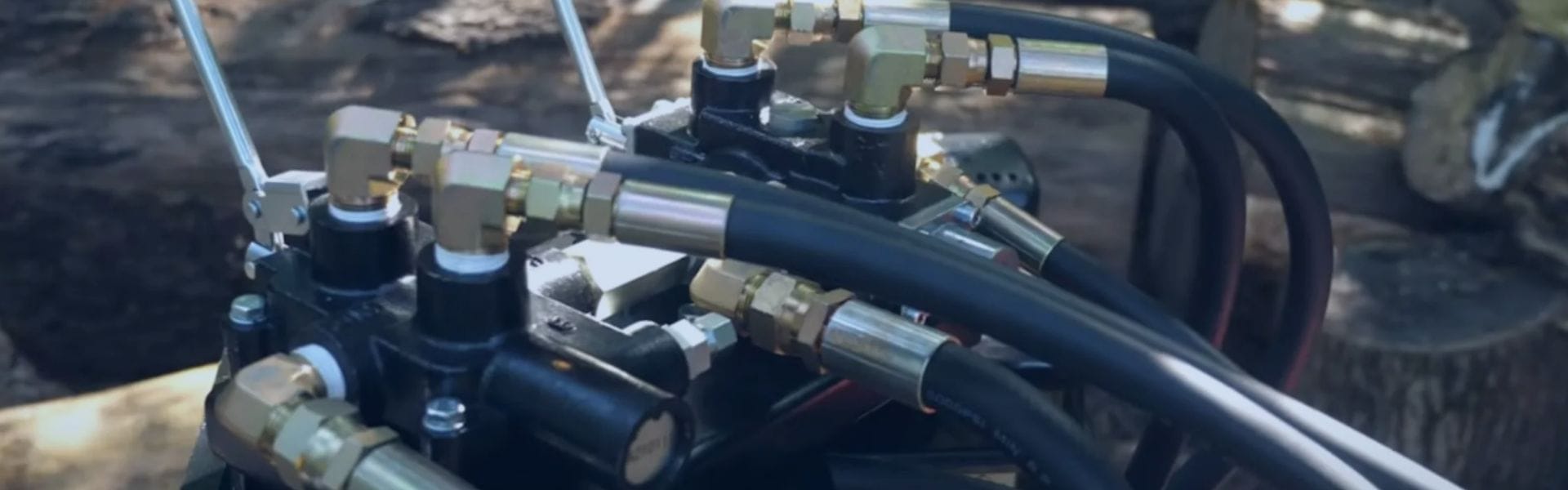
O-ring Failures: Preventing Leaks in Hydraulic Systems
When O-rings fail, the implications can be severe. Leaks resulting
When O-rings fail, the implications can be severe. Leaks resulting
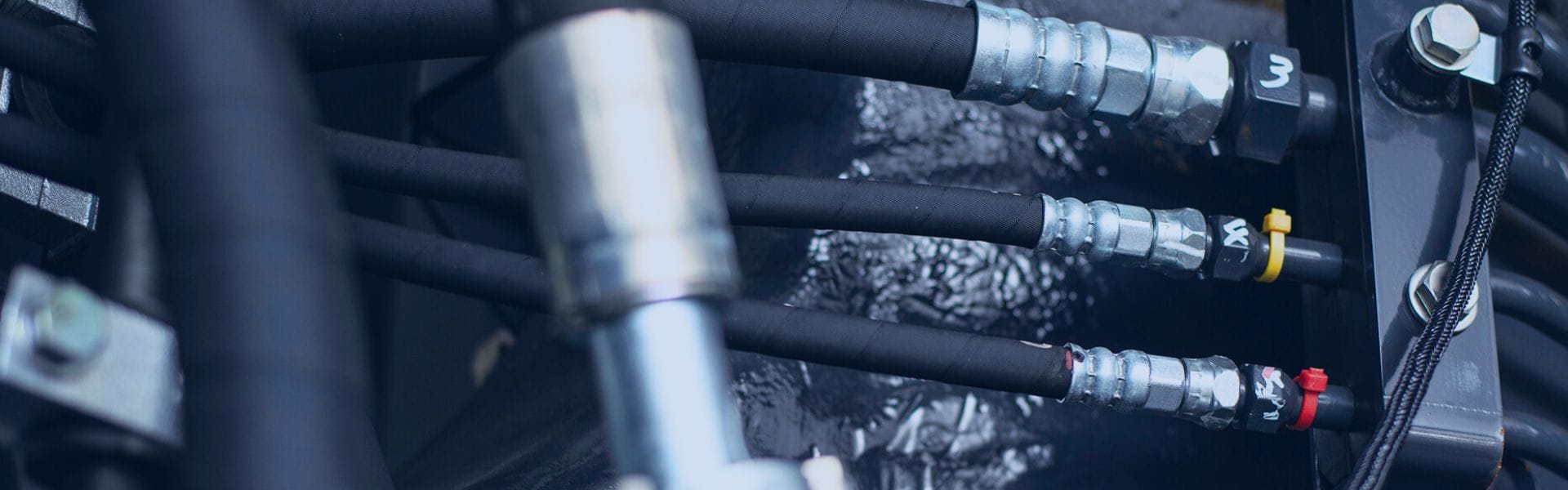
The two primary categories of seals used in hydraulic fittings

SAE J1926 and ISO 6149 are standardized specifications for hydraulic
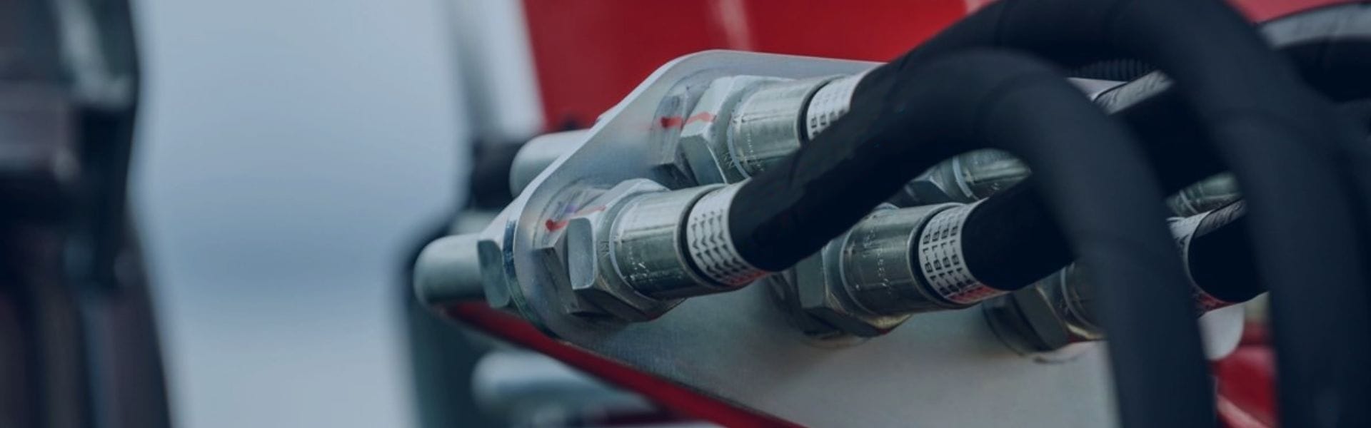
Torque refers to the rotational force applied to fasteners, such
Misalignment and misfits in hydraulic fittings are among the leading

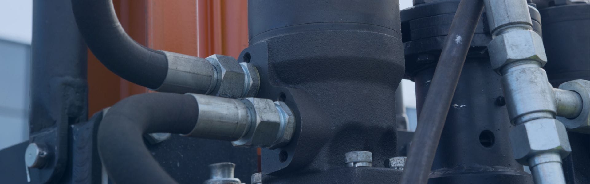
Leaks in hydraulic systems can lead to significant operational inefficiencies

DIN 3852 and ISO 1179 are two standards that govern
Over-bending occurs when a hose is curved beyond its recommended
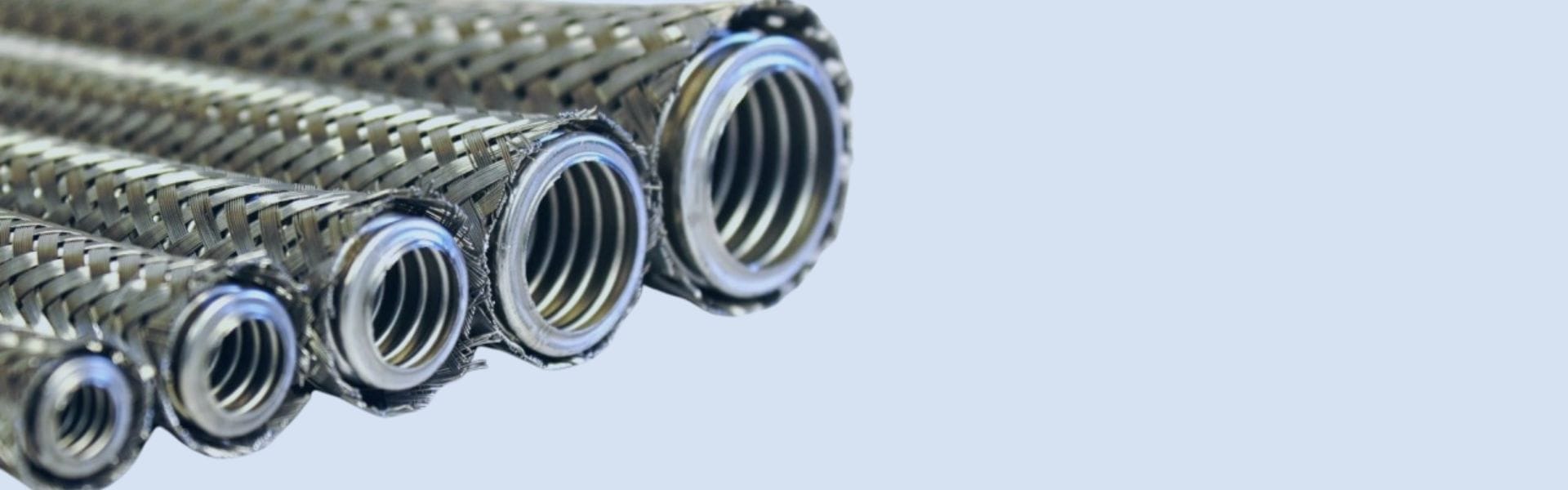
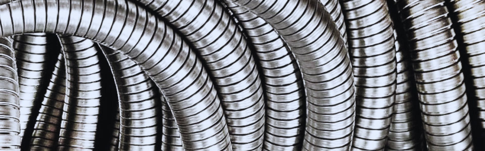
Flexible metal hoses are specialized piping solutions designed to convey
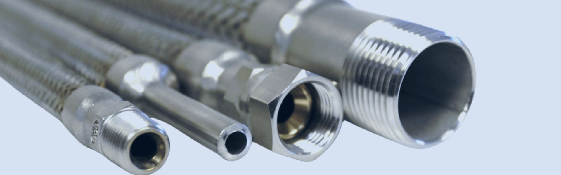
Metal hoses are designed to transport fluids and gases in