Check valves play a crucial role in hydraulic systems, ensuring the smooth and efficient operation of various applications across multiple industries. These devices prevent the backflow of fluids, safeguard equipment, and maintain system pressure. Without check valves, hydraulic systems could suffer from severe operational issues, including fluid contamination, equipment damage, and reduced efficiency.
What is a Check Valve?
A check valve is a mechanical device designed to allow fluid to flow in one direction while preventing reverse flow. Its primary function is to maintain the integrity of hydraulic systems by ensuring that fluids do not flow backward, which can cause damage to equipment, contamination, and loss of system pressure. This one-way flow mechanism is essential in various applications, from simple plumbing systems to complex industrial machinery.
A. Definition and Function
Check valves, also known as non-return valves or one-way valves, operate based on pressure differentials. When the pressure on the inlet side exceeds the pressure on the outlet side, the valve opens, allowing fluid to pass through. Conversely, when the outlet pressure exceeds the inlet pressure, the valve closes, preventing backflow. This functionality is crucial for maintaining the efficiency and safety of hydraulic circuits.
B. Basic Components of a Check Valve
A typical check valve consists of several key components:
Body: The main structure that houses the internal components and connects to the piping system.
Poppet: A movable element that opens and closes the valve based on fluid pressure. It seals the valve when closed, preventing backflow.
Spring: Often used to assist the poppet in closing the valve. It can help maintain the valve in a closed position until the necessary crack pressure is reached.
Retainer: Holds the internal components in place and ensures proper alignment and functioning.
These components work together to create a reliable mechanism that protects hydraulic systems from potential failures.

C. Common Applications Across Industries
Check valves are used in a wide range of applications across various industries, including:
Hydraulic Systems: Ensuring one-way flow in hydraulic circuits, protecting pumps and actuators from backflow.
Water and Wastewater Management: Preventing contamination in water supply systems and managing flow in treatment facilities.
Oil and Gas: Protecting pipelines from pressure surges and ensuring safe operation in drilling and extraction processes.
Manufacturing: Used in various machinery to maintain pressure and prevent fluid leaks in production processes.
Understanding Flow Characteristics
Understanding flow characteristics is essential for selecting the appropriate check valve for any hydraulic application. These characteristics influence how fluids behave within a system and directly impact the performance of check valves. A thorough grasp of flow characteristics ensures that the selected valve can operate effectively under specific conditions, enhancing overall system efficiency.
A. Definition of Flow Characteristics
Flow characteristics refer to the various properties and behaviors of fluids as they move through a hydraulic system. This includes how fluid flows through pipes, valves, and other components, as well as the forces acting on them. Key flow characteristics include flow rate, velocity, pressure, and the nature of the fluid itself (such as its viscosity). By analyzing these characteristics, engineers can predict how fluids will interact with system components, including check valves, and make informed decisions during the selection process.
B. Key Factors Affecting Flow Characteristics
Flow Rate:
Flow rate is the volume of fluid that passes through a specific point in the system over a given time period, typically measured in gallons per minute (GPM) or liters per second (L/s). It is a critical factor in determining the size and type of check valve needed. Higher flow rates may require valves with larger openings or specific designs to minimize pressure drops and ensure that the valve opens and closes appropriately. Understanding the expected flow rate helps in selecting a valve that can handle the system’s demands without causing cavitation or excessive turbulence.
Fluid Viscosity:
Viscosity is a measure of a fluid’s resistance to flow. Fluids with high viscosity, such as oils or sludges, flow more slowly than low-viscosity fluids like water. The viscosity of a fluid affects the flow characteristics significantly, as it influences the force required to move the fluid through pipes and valves. When selecting a check valve, it’s essential to consider the viscosity of the fluid to ensure that the valve can operate effectively without excessive pressure loss or risk of clogging. For example, a check valve in a high-viscosity system may require a larger crack pressure to ensure proper function.
Temperature Variations:
Temperature has a dual impact on fluid behavior and valve performance. As temperature increases, many fluids become less viscous, allowing for easier flow. Conversely, low temperatures can increase viscosity, potentially leading to operational challenges. Additionally, temperature variations can affect the materials used in the construction of check valves. It is crucial to select a valve that can withstand the expected temperature range without degrading or losing functionality. This includes considering material compatibility with the fluid at various temperatures, as certain materials may become brittle or lose structural integrity when exposed to extreme heat or cold.
C. Importance of Understanding These Factors in Selection
Understanding the key factors affecting flow characteristics is vital for several reasons:
Optimal Performance: Selecting the right check valve based on flow characteristics ensures optimal performance and reliability within the hydraulic system. Valves that are appropriately sized and designed for specific flow rates, viscosities, and temperatures will operate more efficiently and reduce the risk of malfunctions.
Cost-Effectiveness: Making informed decisions about valve selection can prevent costly mistakes and reduce downtime due to equipment failures. A well-chosen check valve can enhance system efficiency, potentially lowering operational costs and prolonging the life of other components.
System Safety: Proper understanding of flow characteristics contributes to the safety of hydraulic systems. Check valves that do not meet the specific flow requirements can lead to backflow, pressure surges, or system failures, posing risks to equipment and personnel.
Crack Pressure
Crack pressure is a critical concept in the selection and operation of check valves. It plays a significant role in determining how effectively a valve functions within a hydraulic system. Understanding crack pressure can help engineers and technicians make informed decisions to optimize system performance.
A. Definition of Crack Pressure
Crack pressure refers to the minimum pressure required to open a check valve and allow fluid to flow through it. When the pressure on the inlet side of the valve exceeds this threshold, the valve’s poppet lifts, enabling fluid to pass. Conversely, when the pressure on the outlet side is higher than the inlet pressure, the valve closes to prevent backflow. Crack pressure is a vital parameter, as it directly influences the timing and responsiveness of the check valve within a hydraulic system.
B. How Crack Pressure Affects Flow
The crack pressure of a check valve can significantly impact the flow characteristics of a system:
Flow Regulation: A valve with a low crack pressure will open more easily, allowing fluid to flow quickly, which can be beneficial in systems requiring rapid response times. However, if the crack pressure is set too low, it may lead to unwanted backflow during minor fluctuations in pressure.
Pressure Control: Higher crack pressure can help maintain system pressure by preventing backflow effectively. In applications where pressure stability is crucial, such as in hydraulic systems that require constant pressure to function correctly, selecting a valve with an appropriate crack pressure is essential.
Impact on Efficiency: Incorrectly set crack pressure can lead to inefficient operation. For example, if the crack pressure is too high for a particular application, the valve may not open as intended, restricting flow and causing pressure drops that can impact system performance. Conversely, if it’s too low, it can result in premature valve opening and energy losses.
C. Selecting the Appropriate Crack Pressure for Different Applications
Choosing the right crack pressure involves considering several factors related to the specific application:
System Requirements: Assess the operational parameters of the hydraulic system, including expected flow rates, pressure ranges, and fluid types. Understanding the system’s requirements helps in determining the ideal crack pressure for optimal performance.
Application Environment: Evaluate the environment in which the valve will operate. For instance, systems with significant fluctuations in pressure may require a check valve with a higher crack pressure to prevent unintentional opening.
Fluid Characteristics: The nature of the fluid being used is also critical. More viscous fluids may require different crack pressure settings compared to less viscous fluids due to their flow behavior.
Consultation with Manufacturer Specifications: Manufacturers often provide guidelines and specifications regarding appropriate crack pressure settings for their check valves. Utilizing these resources can help ensure the correct selection for specific applications.
D. Case Studies Showcasing Crack Pressure Impacts
Hydraulic Lift System: In a hydraulic lift system used in automotive service, a check valve with a crack pressure of 10 psi was selected to allow for quick engagement. However, due to frequent backflow during minor pressure fluctuations, a replacement valve with a 15 psi crack pressure significantly improved system stability and reduced maintenance needs.
Chemical Processing Plant: In a chemical processing plant, a low crack pressure valve was initially used, resulting in unwanted backflow and contamination of raw materials. After reassessing the system requirements, engineers switched to a check valve with a crack pressure of 20 psi, which effectively prevented backflow, enhancing both safety and product quality.
Pressure Drop Considerations
A. Definition of Pressure Drop
Pressure drop refers to the reduction in pressure that occurs as fluid flows through a valve or any other restriction in a hydraulic system. It is a critical measurement, as excessive pressure drop can hinder fluid movement, reduce system efficiency, and lead to potential operational issues. The pressure difference is typically measured in pounds per square inch (psi) or pascals (Pa) and is influenced by various factors, including the design of the valve and the characteristics of the fluid.
B. Factors Influencing Pressure Drop in Check Valves
Several factors contribute to the pressure drop across check valves:
Valve Design: The geometry and construction of the check valve significantly affect pressure drop. Valves with sharp corners, abrupt changes in diameter, or complicated internal designs tend to create higher turbulence and resistance to flow, leading to increased pressure drop.
Flow Rate: Higher flow rates can lead to greater pressure drops due to increased friction and turbulence within the valve. Understanding the expected flow rate is essential for selecting a valve that minimizes pressure loss.
Fluid Viscosity: The viscosity of the fluid influences how easily it flows through the valve. Higher viscosity fluids exhibit greater resistance, resulting in increased pressure drop. Engineers must account for fluid viscosity when selecting check valves to ensure optimal performance.
Temperature: Temperature can impact fluid viscosity and, consequently, the pressure drop. As temperature increases, many fluids become less viscous, potentially reducing pressure drop. Conversely, colder temperatures can increase viscosity, leading to higher pressure losses.
Installation Orientation: The orientation of the valve within the piping system can also affect pressure drop. For instance, check valves installed horizontally may experience different flow characteristics than those installed vertically, impacting the overall pressure drop.
C. Implications of Pressure Drop on System Performance
Excessive pressure drop can have several adverse effects on hydraulic systems:
Reduced Efficiency: A high-pressure drop means that more energy is required to maintain the desired flow rate, leading to inefficiencies. This can result in increased operational costs and strain on pumps and other components.
Inadequate Flow: If the pressure drop is too high, it may prevent the valve from opening fully, restricting flow and potentially causing system malfunctions. This is particularly critical in applications requiring precise flow control.
Increased Wear and Tear: The additional stress on components caused by excessive pressure drop can lead to premature wear and failure, increasing maintenance costs and system downtime.
Operational Safety: In certain applications, such as those involving hazardous fluids, a significant pressure drop can lead to unsafe operating conditions, including leaks or ruptures.
D. Strategies for Minimizing Pressure Drop
To mitigate pressure drop across check valves and enhance system performance, consider the following strategies:
Select the Right Valve Design: Choosing check valves with streamlined designs and minimal flow restrictions can help reduce pressure drop. Valves specifically engineered for low-pressure drop applications should be prioritized.
Optimize Valve Size: Ensure the selected check valve is appropriately sized for the system. Valves that are too small can create unnecessary restrictions, leading to increased pressure drop. Conversely, oversizing can lead to other issues, so a balance must be struck.
Maintain Smooth Piping Systems: Minimize bends, turns, and other obstructions in the piping system that can contribute to turbulence and pressure drop. Using smooth and consistent pipe diameters can improve flow efficiency.
Monitor and Control Flow Rates: Regularly assess flow rates and adjust system parameters to maintain optimal performance. Implementing flow control devices may help manage flow rates more effectively, reducing pressure drop.
Consider Fluid Properties: When selecting valves, account for the viscosity and temperature of the fluid. Ensure that the valve can handle variations in fluid properties, which can help maintain consistent pressure drop.
Orifice Fittings and Their Role
A. Explanation of Orifice Fittings
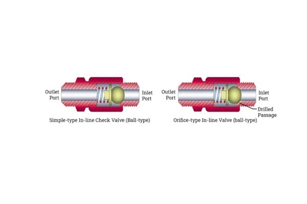
Orifice fittings are components designed to restrict flow in a hydraulic system by creating a precise opening through which fluid can pass. These fittings are often integrated into check valves or other control devices to manage the flow rate and pressure within a system. The orifice itself is typically a small hole or opening that regulates the volume of fluid allowed to flow through, which can be critical for applications requiring precise control.
Orifice fittings can vary in shape, size, and design, depending on the specific application and fluid characteristics. They are commonly used in hydraulic circuits to limit flow rates, reduce pressure surges, and minimize the risk of fluid cavitation.
B. Importance of Orifice Size and Design
The size and design of the orifice are critical factors that influence how effectively it controls flow:
Orifice Size: The diameter of the orifice determines the maximum flow rate that can pass through. A larger orifice allows for higher flow rates but may lead to increased turbulence and pressure drop. Conversely, a smaller orifice can effectively limit flow but may also restrict it excessively, leading to operational inefficiencies. Thus, selecting the right orifice size is essential for balancing flow control and system performance.
Orifice Shape: The design of the orifice, including its shape and smoothness, impacts flow characteristics. For example, a tapered orifice may facilitate a smoother flow transition compared to a straight-edged orifice, thereby reducing turbulence and enhancing efficiency.
Material Considerations: The materials used for orifice fittings must be compatible with the fluids being handled, as this can affect the longevity and reliability of the fitting. Corrosion-resistant materials may be necessary for aggressive fluids, while softer materials may be suitable for less corrosive applications.
C. Impact on Flow Control and System Efficiency
Orifice fittings are crucial for effective flow control and overall system efficiency in several ways:
Flow Rate Regulation: By restricting flow, orifice fittings allow for precise regulation of fluid movement within the system. This is particularly important in applications where maintaining specific flow rates is critical for performance and safety.
Pressure Management: Orifice fittings help manage pressure levels within hydraulic systems by controlling the amount of fluid passing through. This can prevent pressure surges that may lead to equipment damage or system failures.
Cavitation Prevention: By carefully managing flow rates and pressure, orifice fittings can reduce the risk of cavitation—a phenomenon that occurs when vapor bubbles form in a fluid due to low pressure. Cavitation can lead to significant damage in hydraulic systems, making the role of orifice fittings essential in preventing this issue.
Energy Efficiency: Properly sized and designed orifice fittings contribute to energy efficiency by minimizing unnecessary pressure drops and flow restrictions. This can result in lower energy consumption and reduced operational costs.
D. Recommendations for Selecting Orifice Fittings
When selecting orifice fittings for hydraulic applications, consider the following recommendations:
Assess System Requirements: Begin by analyzing the specific needs of the hydraulic system, including flow rates, pressure levels, and fluid properties. Understanding these requirements will guide the selection of the appropriate orifice size and design.
Consult Manufacturer Guidelines: Manufacturers often provide specifications and guidelines for selecting orifice fittings. Utilizing these resources can help ensure that the selected fitting meets the system’s operational needs.
Evaluate Compatibility: Ensure that the materials used for the orifice fittings are compatible with the fluids being handled. This will help maintain the integrity and longevity of the fittings.
Test and Validate: If possible, conduct tests to validate the performance of the orifice fittings within the specific hydraulic system. Monitoring flow rates and pressure changes during operation can provide valuable insights into whether the selected fittings are achieving the desired outcomes.
Consider Installation Location: The placement of orifice fittings within the hydraulic system can influence their performance. Ensure that they are installed in locations that optimize flow and minimize potential issues related to turbulence or pressure drop.
Fluid Compatibility
A. Importance of Fluid Compatibility
The compatibility between the fluid and the materials of the check valve is paramount. Incompatible materials can lead to issues such as:
Corrosion: Fluids that react chemically with valve materials can cause corrosion, leading to structural weaknesses and potential failures.
Leaking: If seals or other components degrade due to fluid incompatibility, it can result in leaks, compromising system integrity and safety.
Contamination: Degradation of valve materials can release particles into the fluid, contaminating the system and affecting downstream components.
Ensuring fluid compatibility helps enhance the reliability and lifespan of check valves, ultimately improving system performance.
B. Common Materials Used in Check Valves
Check valves are typically constructed from a variety of materials, each suitable for different applications:
Metal: Common metals include stainless steel, brass, and carbon steel. Stainless steel is favored for its corrosion resistance and strength, making it ideal for harsh environments.
Plastics: Materials like PVC, CPVC, and PTFE are often used in applications involving corrosive or aggressive fluids. These materials provide excellent chemical resistance.
Elastomers: Seals and gaskets are usually made from elastomeric materials such as nitrile, EPDM, or fluorocarbon, depending on the fluid’s temperature and chemical properties.
Selecting the appropriate material for the valve’s construction and sealing components is vital to ensure long-term compatibility.

C. Guidelines for Ensuring Fluid Compatibility
To ensure fluid compatibility in hydraulic systems, consider the following guidelines:
Consult Material Compatibility Charts: Use compatibility charts provided by manufacturers to match fluids with suitable materials. These charts typically outline which materials are resistant to specific fluids.
Evaluate Operating Conditions: Consider the temperature and pressure conditions under which the check valve will operate. These factors can significantly affect material performance.
Conduct Compatibility Testing: If uncertain, conduct tests to assess how materials respond to specific fluids over time. This can help identify potential issues before full-scale implementation.
Account for Fluid Properties: Assess the fluid’s chemical composition, including corrosiveness, viscosity, and temperature stability, to select appropriate materials.
Conclusion
As technology and methodologies in fluid dynamics evolve, so too must our knowledge and practices. We encourage readers to seek further education on check valve technologies and their applications. Engaging with industry resources, attending relevant training sessions, and consulting with experts can provide valuable insights that enhance decision-making processes.
FAQ
What is a check valve?
A check valve is a mechanical device that allows fluid to flow in one direction only, preventing backflow in hydraulic systems.
Why is flow characteristic important in check valve selection?
Understanding flow characteristics, such as crack pressure and pressure drop, helps ensure that the valve meets the specific flow requirements of the application, enhancing system efficiency.
What materials are commonly used in check valves?
Common materials include stainless steel, brass, plastic (PVC, CPVC), and elastomers for seals, chosen based on fluid compatibility and operating conditions.
How do I determine if a fluid is compatible with a check valve?
Use manufacturer compatibility charts, material safety data sheets (MSDS), and online resources to assess whether the valve materials can withstand the fluid’s chemical properties.
What factors should I consider when selecting an orifice fitting?
Consider orifice size, shape, fluid viscosity, and flow rate requirements to ensure optimal flow control and system performance.
How can I minimize pressure drop across a check valve?
Select appropriately sized valves, use smooth piping, and avoid sharp bends or restrictions in the system to reduce turbulence and pressure loss.