Hydraulic fittings are critical connection points in fluid power systems where precision and reliability are non-negotiable. For technical and procurement personnel, understanding these components’ complex specifications is essential for system safety, performance, and longevity. This article provides expert analysis of key parameters including working pressure, burst pressure, and temperature ranges, equipping you with knowledge to make informed decisions when selecting these vital components.
Understanding Hydraulic Fitting Fundamentals
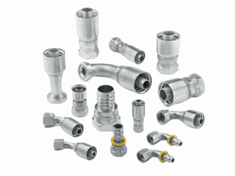
Types of Hydraulic Fittings and Their Applications
Hydraulic fittings come in various configurations designed for specific applications:
- Compression fittings: Utilize ferrules for leak-proof seals in moderate-pressure applications
- Flare fittings: Feature flared tube ends creating metal-to-metal seals for high-pressure systems
- O-ring face seal fittings: Incorporate elastomeric O-rings for superior sealing in high-vibration environments
- Bite-type fittings: Use cutting rings that bite into the tube for reliable heavy-duty connections
- Flange connections: Provide robust connections for large-diameter tubing in high-pressure systems
Each type offers distinct advantages in pressure capacity, assembly ease, and resistance to vibration and temperature fluctuations.
Material selection significantly influences performance:
| Material | Temperature Range (°C/°F) | Pressure Coefficient | Applications |
| Carbon steel | -40 to +100 / -40 to +212 | 1 | Standard industrial applications |
| Stainless steel | -54 to +200 / -65 to +392 | 0.9 | Corrosive environments, high-temperature |
| Brass | -53 to +204 / -63.4 to +399 | 0.7 | Corrosion-resistant applications |
| Aluminum alloy | -40 to +100 / -40 to +212 | 0.5 | Weight-sensitive applications |
Industry Terminology Explained
Essential terminology for proper specification:
- Working pressure: Maximum pressure for safe operation including spikes
- Burst pressure: Minimum pressure causing failure under laboratory conditions
- Proof pressure: Maximum pressure without performance alteration (typically twice working pressure)
- Safety factor: Ratio of burst pressure to working pressure (typically 4:1)
- Minimum bend radius (MBR): Smallest safe bending radius
- Inside/Outside diameter (I.D./O.D.): Critical dimensions for flow and fitting selection
Critical Technical Parameters Explained
Working Pressure Specifications
Working pressure represents the maximum pressure hydraulic fittings can safely handle during normal operation. Key considerations include:
- System requirements: Fitting’s working pressure must meet/exceed system’s maximum pressure
- Safety margin: Industry standards require margins above nominal operating pressure
- Component rating: Assembly’s working pressure equals lowest-rated component
- Dynamic vs. static pressure: Ratings differ based on system conditions
Working pressure specifications by fitting type and size:
| Fitting Type | Size Range (mm) | Working Pressure (MPa/psi) |
| 24° cone (ISO 8434-1) | 4-12 | 35/5,075 |
| 24° cone (ISO 8434-1) | 14-22 | 28/4,060 |
| 24° cone (ISO 8434-1) | 25-42 | 21/3,045 |
| O-ring face seal (ISO 8434-3) | 4-16 | 42/6,090 |
| O-ring face seal (ISO 8434-3) | 18-38 | 35/5,075 |
| 37° flare (SAE J514) | 4-16 | 28/4,060 |
| 37° flare (SAE J514) | 18-38 | 21/3,045 |
Burst Pressure Ratings and Safety Factors
Burst pressure is the minimum pressure a fitting withstands before failure. The relationship with working pressure is defined by the safety factor:
Safety Factor = Burst Pressure ÷ Working Pressure
Industry standards require a 4:1 safety factor, meaning burst pressure should be four times the rated working pressure. For example:
- 5,000 psi working pressure requires 20,000 psi burst pressure
- 35 MPa working pressure requires 140 MPa burst pressure
This safety margin accounts for:
- Unexpected pressure spikes
- System vibration and shock
- Material fatigue
- Installation variables
- Temperature fluctuations
Factors reducing safety margin include improper installation, corrosion, excessive temperature, mechanical damage, and wear.
Temperature Range Considerations
Temperature significantly impacts hydraulic fitting performance. Standard fittings typically operate within -40°C to +100°C (-40°F to +212°F), with specialized materials extending this range.
Temperature effects on pressure ratings:
| Temperature (°C/°F) | Pressure Coefficient | Example: 35MPa Fitting Actual Working Pressure |
| -40 to +38 / -40 to +100 | 1 | 35.0 MPa / 5,075 psi |
| +39 to +65 / +102 to +149 | 0.9 | 31.5 MPa / 4,568 psi |
| +66 to +93 / +150 to +199 | 0.75 | 26.3 MPa / 3,806 psi |
| +94 to +121 / +200 to +250 | 0.65 | 22.8 MPa / 3,299 psi |
| +122 to +149 / +251 to +300 | 0.5 | 17.5 MPa / 2,538 psi |
| +150 to +204 / +301 to +399 | 0.4 | 14.0 MPa / 2,030 psi |
High temperatures cause reduced material strength, accelerated seal aging, decreased pressure capacity, and thermal expansion. Low temperatures increase brittleness, reduce flexibility, and may cause seal shrinkage.
Flow Capacity and Pressure Drop
Flow capacity and pressure drop are interrelated parameters affecting system efficiency. Inside diameter (I.D.) directly influences these factors.
Flow capacity is the maximum fluid volume passing through a fitting without excessive pressure loss. Inadequate capacity causes system inefficiency, increased energy consumption, heat generation, and reduced actuator performance.
Pressure drop occurs as fluid encounters resistance, representing energy loss. Factors affecting pressure drop include:
- Fitting geometry
- Surface roughness
- Flow velocity
- Fluid viscosity
- Fitting size
The relationship follows this principle:
Pressure Drop ∝ (Flow Rate)² ÷ (Diameter)⁵
Recommended flow velocities:
- Suction lines: 0.6-1.2 m/s (2-4 ft/s)
- Pressure lines up to 3.5 MPa: 2.4-4.6 m/s (8-15 ft/s)
- Pressure lines above 3.5 MPa: 4.6-6.1 m/s (15-20 ft/s)
- Return lines: 1.5-3.0 m/s (5-10 ft/s)
Thread Types and Dimensional Standards
Thread specifications ensure proper fit, sealing, and pressure retention. Common thread types include:
Parallel threads (straight):
- Metric parallel (M): ISO 261, ISO 262
- British Standard Pipe Parallel (BSPP/G): ISO 228
- National Pipe Straight (NPSM): ANSI B1.20.1
Tapered threads (conical):
- National Pipe Tapered (NPT): ANSI B1.20.1
- British Standard Pipe Tapered (BSPT/R): ISO 7
- Dryseal (NPTF): SAE J476
Special hydraulic threads:
- UN/UNF: SAE J514, ISO 8434-2
- Metric ISO 6149: ISO 6149-1, ISO 6149-2, ISO 6149-3
- JIS threads: JIS B0202
Metric and imperial thread cross-reference:
| Metric Thread | Imperial Thread | Applicable Standard | Common Applications |
| M10x1.0 | 3/8-24 UNF | ISO 8434-1 / SAE J514 | Small hydraulic systems |
| M14x1.5 | 1/2-20 UNF | ISO 8434-1 / SAE J514 | Medium hydraulic systems |
| M18x1.5 | 3/4-16 UNF | ISO 8434-1 / SAE J514 | Medium-large systems |
| M22x1.5 | 7/8-14 UNF | ISO 8434-1 / SAE J514 | Large hydraulic systems |
| M27x2.0 | 1-1/16-12 UN | ISO 8434-1 / SAE J514 | Heavy-duty systems |
ISO Standards and Certification Requirements
ISO 8434 Series Standards Overview
The ISO 8434 series provides comprehensive standards for metallic tube connections:
- ISO 8434-1:2018: Specifies requirements for 24° cone connectors using cutting rings and O-ring seal cones (DKO) for tubes with 4-42mm outside diameters
- ISO 8434-2: Covers 37° flare connectors
- ISO 8434-3: Addresses O-ring face seal fittings
- ISO 8434-4: Focuses on 24° cone connectors with O-rings for heavy-duty applications
- ISO 8434-5: Defines test methods for threaded hydraulic fluid power connection fittings
These standards work with ISO 6149, ISO 1179, ISO 9974, and ISO 12151 series to ensure consistent quality, reliable performance, interchangeability, and safety compliance.
Testing Methodologies and Validation Procedures
ISO 8434-5 establishes standardized test methods for certifying hydraulic fittings:
- Proof Pressure Test
- Purpose: Verify fitting withstands pressure without degradation
- Procedure: Apply twice rated working pressure
- Criteria: No leakage, deformation, or performance change
- Burst Pressure Test
- Purpose: Determine failure pressure
- Procedure: Gradually increase pressure until failure
- Requirement: Minimum 4x rated working pressure
- Cyclic Endurance Test
- Purpose: Evaluate performance under repeated pressure cycles
- Procedure: Subject to specified cycles (typically 100,000+)
- Criteria: No leakage or failure throughout testing
- Vacuum Test
- Purpose: Assess integrity under negative pressure
- Criteria: No collapse or deformation
- Overtorque Test
- Purpose: Evaluate response to excessive installation torque
- Criteria: No catastrophic failure or immediate leakage
Test reports must include date, location, sample identification, parameters, results, and authorized signature.
International Certification Bodies and Their Requirements
Major certification bodies include:
- International Organization for Standardization (ISO)
- Key standards: ISO 8434, ISO 6149, ISO 1179 series
- Recognition: Worldwide acceptance
- Society of Automotive Engineers (SAE)
- Key standards: SAE J514, SAE J1926, SAE J2244
- Recognition: Global, primarily North America
- Deutsches Institut für Normung (DIN)
- Key standards: DIN 2353, DIN 3861, DIN 3865
- Recognition: European focus with global acceptance
- British Standards Institution (BSI)
- Key standards: BS 5200, BS EN ISO series
- Recognition: European and Commonwealth countries
Certification requirements typically include product testing, quality management system compliance, documentation, factory audits, ongoing surveillance, and traceability.
Technical Parameter Comparison Tables
Working Pressure vs. Fitting Type and Size
| Fitting Type | Size Range (mm) | Working Pressure (MPa/psi) | Burst Pressure (MPa/psi) | Safety Factor |
| 24° cone (ISO 8434-1) | 4-12 | 35/5,075 | 140/20,300 | 4:1 |
| 24° cone (ISO 8434-1) | 14-22 | 28/4,060 | 112/16,240 | 4:1 |
| 24° cone (ISO 8434-1) | 25-42 | 21/3,045 | 84/12,180 | 4:1 |
| O-ring face seal (ISO 8434-3) | 4-16 | 42/6,090 | 168/24,360 | 4:1 |
| O-ring face seal (ISO 8434-3) | 18-38 | 35/5,075 | 140/20,300 | 4:1 |
| 37° flare (SAE J514) | 4-16 | 28/4,060 | 112/16,240 | 4:1 |
| 37° flare (SAE J514) | 18-38 | 21/3,045 | 84/12,180 | 4:1 |
Inverse relationship between size and pressure:
As the size of the joint increases, the working pressure generally decreases. This is because:
- The increased surface area of larger size fittings results in greater separation forces due to internal pressure
- Larger diameters require thicker wall thicknesses to withstand the same pressures
- Manufacturing process limitations affect the pressure capacity of larger fitting sizes
Joint type performance differences:
- O-ring face seal fittings typically offer the highest pressure ratings due to their superior seal design
- 24° taper fittings provide excellent pressure performance in the small to medium size range
- 37° and 30° flare fittings are widely used in North America and Europe, respectively, but have slightly lower pressure ratings
- Compression fittings offer the lowest pressure ratings, but are easy to install and less costly
Consistent Safety Factor:
All fitting types maintain an industry-standard 4:1 safety factor, regardless of pressure rating. This ensures:
- Consistency and predictability in system design
- Safety margins in a variety of applications
- Compliance with international standards and regulatory requirements
Size Segmentation:
- Small size fittings (4-16mm) consistently provide higher pressure capability for high pressure precision applications
- Medium sizes (18-25mm) provide balanced pressure and flow characteristics
- Large size fittings (30-42mm) optimized for low pressure, high flow applications
Material Performance Comparison
| Material | Temperature Range (°C/°F) | Corrosion Resistance | Pressure Coefficient | Common Applications |
| Carbon Steel | -40 to +100 / -40 to +212 | Low | 1 | General industrial |
| Stainless Steel | -54 to +200 / -65 to +392 | Excellent | 0.9 | Food processing, marine, chemical |
| Brass | -53 to +204 / -63.4 to +399 | Good | 0.7 | Corrosive environments |
| Aluminum | -40 to +100 / -40 to +212 | Moderate | 0.5 | Weight-sensitive applications |
Material Performance Considerations
Corrosion Resistance Factors
- Environmental Exposure: Indoor vs. outdoor usage conditions
- FluidCompatibility: Chemical compatibility with the working fluid
- Galvanic Corrosion: Electrochemical reactions when different metals are in contact
- Operating Temperature: High temperatures typically accelerate the corrosion process
- Exposure to Cleaning Chemicals: Chemicals used during maintenance
Strength Considerations
- Tensile Strength: Maximum stress a material can withstand while being stretched before failure
- Yield Strength: Stress level at which a material begins to deform permanently
- Fatigue Resistance: Performance under cyclic loading
- Impact Resistance: Ability to absorb sudden shocks or impacts
- High-Temperature Creep Resistance: Ability to resist deformation under sustained stress at elevated temperatures
Manufacturing Impact
- Machinability: Ease of shaping the material into complex forms
- Thread Quality: Ability to form precise, durable threads
- Surface Finish: Achievable surface quality and sealing performance
- Dimensional Stability: Ability to maintain dimensional accuracy under temperature changes
- Plating/Coating Options: Available surface treatment methods
Application-Specific Considerations
- Weight-Sensitive Applications: Aluminum alloys and titanium alloys offer significant weight advantages
- High-Temperature Environments: Stainless steel, titanium, and specific brass alloys perform best
- Cryogenic Applications: Certain stainless steels and titanium alloys retain toughness
- Cost-Sensitive Projects: Carbon steel and brass offer the best cost-performance ratio
- Food and Medical Applications: 316 stainless steel is preferred for its hygienic properties and compliance with sanitary standards
Temperature Effects on Pressure Ratings
| Temperature (°C/°F) | Carbon Steel Pressure Factor | Stainless Steel Pressure Factor | Example: 35MPa Carbon Steel Fitting |
| -40 to +38 / -40 to +100 | 1 | 1 | 35.0 MPa / 5,075 psi |
| +39 to +65 / +102 to +149 | 0.9 | 0.95 | 31.5 MPa / 4,568 psi |
| +66 to +93 / +150 to +199 | 0.75 | 0.85 | 26.3 MPa / 3,806 psi |
| +94 to +121 / +200 to +250 | 0.65 | 0.8 | 22.8 MPa / 3,299 psi |
These Data Clearly Show:
All Materials Experience Pressure Derating at Elevated Temperatures
- Within the normal operating temperature range (approximately +1°C to +38°C / +34°F to +100°F), all materials maintain their full pressure ratings.
- Above +38°C (100°F), pressure derating begins to become noticeable.
- Beyond +93°C (199°F), the pressure reduction becomes significantly more pronounced.
- Some materials have absolute temperature limits, beyond which use is not recommended due to safety or performance constraints.
Significant Differences Between Materials
- Stainless steel retains the best pressure-holding capacity at high temperatures, making it the preferred choice for elevated-temperature applications.
- Carbon steel and brass exhibit more substantial pressure reductions under high heat.
- Aluminum alloys show the fastest performance degradation at elevated temperatures and are generally not recommended for use above +100°C (212°F).
- At the low-temperature end, brass and aluminum alloys show minor pressure derating, while carbon steel and stainless steel maintain full ratings.
Nonlinear Nature of Temperature Effects
Pressure derating is not linear; it accelerates at specific temperature thresholds.
Key inflection points typically occur at:
+65°C (149°F)
+93°C (199°F)
+149°C (300°F)
These thresholds correlate with material property changes and safety standard requirements.
Conclusion
Understanding hydraulic fitting technical parameters is essential for system safety, performance, and longevity. From working pressure and burst pressure to temperature considerations and material selection, each specification plays a vital role in proper system functioning. If you need to purchase hydraulic couplings, contact Topa directly, we can make the perfect product according to your requirements!
FAQ
What is the difference between working pressure and burst pressure?
Working pressure is the maximum pressure a fitting can safely handle during normal operation. Burst pressure is the minimum pressure causing failure under laboratory conditions. Industry standard requires a 4:1 safety factor, meaning burst pressure should be four times the working pressure.
How does temperature affect the pressure rating of hydraulic fittings?
As temperature increases, maximum allowable working pressure decreases according to specific derating factors. For example, a fitting rated at 35 MPa at normal temperatures may only be rated for 14 MPa at 150-204°C. Different materials also respond differently to temperature changes.
What standards govern hydraulic fitting specifications?
Key standards include the ISO 8434 series for metallic tube connections, ISO 6149 for metric thread ports, SAE J514 for 37° flare fittings, and DIN 2353 for compression fittings. These define dimensions, performance requirements, testing methodologies, and certification criteria.
How do I select the correct fitting material for my application?
Consider operating temperature range, pressure requirements, corrosion environment, fluid compatibility, and cost constraints. Carbon steel suits general applications, stainless steel for corrosive environments and higher temperatures, brass for moderate corrosion resistance, and aluminum for weight-sensitive applications.
What is the significance of the minimum bend radius in hydraulic systems?
The minimum bend radius (MBR) indicates the smallest radius to which a hose can be safely bent without damage. Exceeding this limit can cause kinking, reduced flow capacity, premature failure, and safety hazards. A smaller MBR provides greater installation flexibility, especially in confined spaces.
How do I convert between metric and imperial fitting sizes?
While exact equivalents rarely exist, functional equivalents with similar performance characteristics are used. Common conversions include 6mm to 1/4 inch, 10mm to 3/8 inch, and 12mm to 1/2 inch. When converting threads, consider diameter, pitch, angle, functional length, and sealing mechanism